Presenting thread
HERE
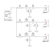
Schematic and pcb screenshot post #1 , plenty o pictures after .
Tips and Tricks thread
HERE
Reading entire thread is advisable , same as inquiring any technical question there : Be sure that you are aware of all things electrical and mechanical !
THF51-S still available on fleabay , watanabetomoaki confirmed seller , also pras1701 - being member here and you have some discount vs. fleabay price
instead , pretty much sure that 2SK180 will work too
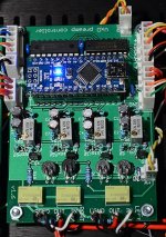
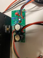
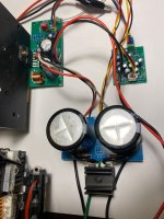
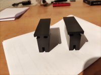
Pcbs are made for UMS , mounting directly to heatsink (will show you how).
NB that pcbs are common for SissySIT And Babelfish M25 amps , differences being really minor , except upper output device .
Do not hurry - read , think , ask and only when you feel that you want it and can make it , proceed ...... advice which I'm finding applicable on practically anything 😉 .
For anything else , write either here , send PM or directly to >zenmodiyaudio@gmail.com<
Prices are mostly dictated with small scale nature of operation (as always is case) and time/work involved in matching and soldering little buggers.
For ordering , contact me at above written e-mail addy .
Kit options :
1.
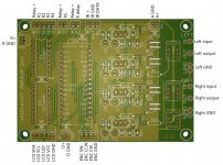
- LCH pcb ,
- RCH pcb ,
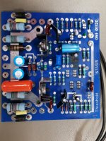
- all smd buffer JFets presoldered ,
- Hall current sensing chips presoldered ,
- surrounding smd caps presoldered ,
- 4pcs of 1uF MKC caps (for critical signal position) enclosed.
Full price , including Paypal fee and P&P for registered shipping all around the Globe - 130E
2.
- LCH pcb ,
- RCH pcb ,
- all smd buffer JFets presoldered ,
- Hall current sensing chips presoldered ,
- surrounding smd caps presoldered ,
- 4pcs of 1uF MKC caps (for critical signal position) enclosed.
-all multiturn trimpots
-output P channel mosfets , 2 pcs , most likely Infineon IRFP9140
-voltage regs
-cascode bjts
-optocouplers
-all electrolytic caps (all Panasonics ,except Elna Silmic II for 1 signal route position)
-one-pin sockets for special resistor positions
-all (MF 600mW) resistors
-small u22 caps for Borbely WC follower , if you want it for more sugar
to recapitulate - everything what goes on pcbs , excluding signal xformers and pcb/mosfet mounting screws/nuts/washers and , of course , excluding THF51-S
Full price , including Paypal fee and P&P for registered shipping all around the Globe - 175E
If I have everything in drawers in moment of order , can ship in 3-5 days ;
If I don't have any of normal parts in drawer , shipping could be delayed up to 3 days;
If I don't have pcbs in drawer , shipping could be delayed up to 7 days;
If I don't have most critical part for getting in my neck of wood - ACS Hall chips , shipping could be delayed up to 3 weeks.

.jpeg")
.jpeg")


 Account banned, as it is the return of a previously banned account. ]