You are using an out of date browser. It may not display this or other websites correctly.
You should upgrade or use an alternative browser.
You should upgrade or use an alternative browser.
Filters
Show only:
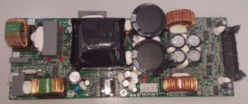
PASCAL S-PRO2 - HELP!!!
Hi Everyone
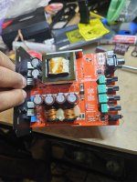
I was using this module in a Professional Audio Subwoofer. One day it blew and certain small components were burnt such that they are unidentifiable. I am a certified Electronics Technician and would like to have the chance to repair my module,. If you have this module in your equipment and you would like to help, please help me identify the following parts. I need to know the values/part numbers of the following components:
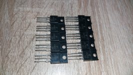
TRANSISTORS
T503, T506, T509, T511
DIODES
D502, D504, D506, D508, D520, D522
IC'S
IC501, IC505
RESISTORS
R500, R507, R511, R520, R527, R576*, R573*
CAPACITORS
C138, C205, C229
Thank you for reading. Let me know.
I was using this module in a Professional Audio Subwoofer. One day it blew and certain small components were burnt such that they are unidentifiable. I am a certified Electronics Technician and would like to have the chance to repair my module,. If you have this module in your equipment and you would like to help, please help me identify the following parts. I need to know the values/part numbers of the following components:
TRANSISTORS
T503, T506, T509, T511
DIODES
D502, D504, D506, D508, D520, D522
IC'S
IC501, IC505
RESISTORS
R500, R507, R511, R520, R527, R576*, R573*
CAPACITORS
C138, C205, C229
Thank you for reading. Let me know.
VTA ST120 - Troubleshooting - Only 1 Channel Operational
- By Cutts
- Tubes / Valves
- 2 Replies
Hi All.
I'm seeking assistance in solving a problem with a tubes4hifi ST120 that I built about 4 months ago. The unit only plays through 1 channel. It's a long story as to how this happened, though in summary, I managed to insert and seat one of the the KT88 incorrectly. It was rotated by 1 pin. When the unit was energized, the 100k resister popped, there was smoke and a fair degree of cursing. I replaced the resistor, thinking this was the only part I damaged, though the unit still only plays on 1 channel.
I've performed many comparative tests, though cannot pinpoint what other parts need replacing.
My first question to the forum is: Has anyone performed something similar and can help me pinpoint the problem?
If not, I'll add to this post in the coming days as to what I've done to try and identify/ isolate the broken part(s).
Regards.
Andrew
Hi
- By mightymini
- Introductions
- 1 Replies
My name is Tasos i am living in Crete - Greece looking always for new stuff and information and i end up here.
I've got an Digital streamer running volumio and the end stage is Ians trasportpi digi. Very pleased with that.
I've got an Digital streamer running volumio and the end stage is Ians trasportpi digi. Very pleased with that.
Cambridge Azur 540 amp protection fault except on headphones
- By montyzoomer
- Solid State
- 1 Replies
Hi, I have the v1 of this amp. It goes into CAP5 protect (4 flashes, indicating speaker terminal short). But if I plug in headphones, the amp powers up normally.
I have tested the speaker output board and the output transistors for shorts and can't find any? Also, If I unplug the 3 pin connector CN3 - CN8 between the mains power board and the amp board (marked relay), the amp also powers up. Is this a fault in the main power relay or the speaker relay? Any ideas?
I have tested the speaker output board and the output transistors for shorts and can't find any? Also, If I unplug the 3 pin connector CN3 - CN8 between the mains power board and the amp board (marked relay), the amp also powers up. Is this a fault in the main power relay or the speaker relay? Any ideas?
Dynavox VR70-11E are there internal fuses please
- By jkojic
- Tubes / Valves
- 0 Replies
a tube was shorting out inside a el34 - making horrible noise - i swapped for a new one but channel r is completely dead - i looked at circuit diagram - could not find any fuses are there any please
Older driver "aging" problems - from a thread on our local club's website
New to the game - recap an amp (Rotel RA-840BX3)
- Solid State
- 1 Replies
Hey all,
I'm really new to the game, but have worked on pinball machines and some other odds and ends over the years, so working on circuit boards isn't outside of my wheelhouse. I currently have a Rotel RA-840BX3 that's on the fritz (has a broken bias potentiometer). As I'm ordering parts anyhow, I tested the readily available (read: huge 50V 10000uf) caps on the board, and one is dead, so I intend to replace those as well.
I have the schematic and service manual, but have never done a recap. I'm wondering a) if there's any particular way other than poring over the schematic to find the caps required, b) if there are any capacitors that are generally replaced and generally left alone, and c) how a guy goes about learning how that schematic hangs together i.e. what is each part of the circuit doing? I can easily test out a given component, but I don't entirely know how to say "oh, these components are the phono stage; this is the power supply" and so on. I've done some Googling and YouTube-ing and whatnot, but feel like I'm on a bit of a fishing expedition and not catching much. I figured as opposed to taking a shotgun approach, I'd try to learn to do it right. Thanks in advance for the help; really appreciate it.
Audiozen AZ OLED setup kits for Soekris dam1021/1121 (new unused)
As I am slimming out my DIY projects backlog due to the lack of time building all the stuff lying around I will post many undone projects and PCBs I collected over time.
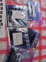
For sale is a complete set of Audiozens AZOled Kit (SK lite). Kit has never been used and was meant to built for a friend who never responded so it was lying around for some time in my stock.
New and unsoldered transformer, protective film still over the oled display.
Asking what I originally paid 130 usd + shipping + PP fees.
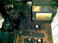
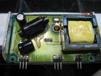
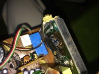
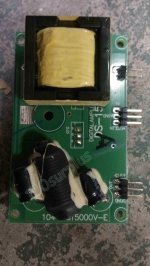
DS-15 Class-D Modul with much Trouble and used in a lot of Models from Harman//JBL
- Class D
- 30 Replies
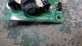
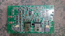
For this modul (PCB card naming "104-DS15000V-E") - go to
DS-15 104-DS15000V-E Digital amplifier module on 100surplus.com
and
Harman Kardon JB?L Infinity Subwoofer PCB Card 051 B00012A E 104 DS15000V E | eBay
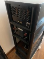
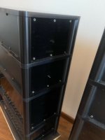
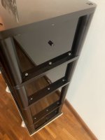
I want the name of manufacturer, a schematic diagram and the reason for a lot of trouble in some subwoofer-models so as the right modification steps to get more reliability.
In follow subwoofer modules, which I know, this class-d card is in use
1) Harman Sub-TS11
2) JBL CSS10
3) JBL Sub-160
3) Harman TS2BQ
Follow German threads mentioned the trouble with it:
Heco Sub 30A Kondensatoren platt?, Elektronik (Stereo&Surround) - HIFI-FORUM
DS-15 104-DS15000V-E nachbau, Elektronik (Stereo&Surround) - HIFI-FORUM
I am a tech and have a JBL SUB 160 that sits and screaches.
Reperatur - aber wie? TS2BQ Harman/Kardon, Subwoofer - HIFI-FORUM
[gelöst] Wer kennt diese Bauteile (Feldeffekttransistor)? - Mikrocontroller.net
Thank you for your help.
Unfortunately this thread don't provide the right information:
I am a tech and have a JBL SUB 160 that sits and screaches.
The discrete topology must actually be easy - the IC from last image is a TL072 in a SO-8 outline.
DS-15 104-DS15000V-E Digital amplifier module on 100surplus.com
and
Harman Kardon JB?L Infinity Subwoofer PCB Card 051 B00012A E 104 DS15000V E | eBay
I want the name of manufacturer, a schematic diagram and the reason for a lot of trouble in some subwoofer-models so as the right modification steps to get more reliability.
In follow subwoofer modules, which I know, this class-d card is in use
1) Harman Sub-TS11
2) JBL CSS10
3) JBL Sub-160
3) Harman TS2BQ
Follow German threads mentioned the trouble with it:
Heco Sub 30A Kondensatoren platt?, Elektronik (Stereo&Surround) - HIFI-FORUM
DS-15 104-DS15000V-E nachbau, Elektronik (Stereo&Surround) - HIFI-FORUM
I am a tech and have a JBL SUB 160 that sits and screaches.
Reperatur - aber wie? TS2BQ Harman/Kardon, Subwoofer - HIFI-FORUM
[gelöst] Wer kennt diese Bauteile (Feldeffekttransistor)? - Mikrocontroller.net
Thank you for your help.
Unfortunately this thread don't provide the right information:
I am a tech and have a JBL SUB 160 that sits and screaches.
The discrete topology must actually be easy - the IC from last image is a TL072 in a SO-8 outline.
Attachments
-
 DS-15 aktivmodul-ts2bq_206643.jpg126.1 KB · Views: 3,303
 -
 DS-15 ds150-1_459802.jpg34.5 KB · Views: 3,276
 -
 DS-15 dsc-0130_541664.jpg93.5 KB · Views: 2,533
 -
 DS-15 heco-sub-30a-bild-1_427057.jpg112.7 KB · Views: 2,596
 -
 DS-15 jc131018-143_1_.jpg140 KB · Views: 2,774
 -
 DS-15 jc131018-143_2_.jpg84.9 KB · Views: 2,413
 -
 DS-15 jc131018-143_3_.jpg96.5 KB · Views: 2,064
New Member
- By Vit4min4s
- Introductions
- 3 Replies
Hello everyone again,
I have been in this forum since 2021, Unfortunatly I am having issues with the old account, I cannot receive the reactivation link so I had to create a new one,
Thanks!
I have been in this forum since 2021, Unfortunatly I am having issues with the old account, I cannot receive the reactivation link so I had to create a new one,
Thanks!
Help with troubleshooting faint buzzing noise from headphones
- By Gula Melaka
- Headphone Systems
- 12 Replies
Hi All,
I have recently started a project to build my own headphone amplifier from scratch. I like the sound of the resulting amplifier, but hearing some hum (initially but solved by reducing bias in the output stage) and a faint static like buzzing noise that does not change with turning the pot either way. I hope kind fellow members here can help to shed some light or provide suggestions to solve the buzzing noise.
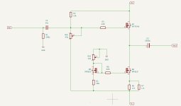
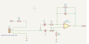
The schematic of the power supply, voltage gain stage and output stage are as attached (all separate PCBs, 1 for voltage gain stage, 2 for left and right channels of the output stage.
1. Power supply: I figure it is easier to connect with all the connections located on the PCB, therefore included terminal blocks for AC input, power switch, transformer primary and secondary all onboard. The transformer voltage is 17-0-17. I have adjusted the trimpots so that the final DC output with no load is +-15V. The board has 3 output terminal blocks connected in parallel so that the voltage gain stage and the output stages all share a single power source.
2. Voltage gain stage: since this is my first attempt at building a headphone amplifier, I am not sure what kind of voltage is required, therefore started with a gain of 5. The 100k resistor in front of the volume pot is to attenuate the signal since I find that the gain is a bit too much for my headphone.
3. Output stage: I have set the bias initially to 400mA per channel, and later reduced it to 200mA.
The problem: initial biasing and offset nulling went as planned. When I pluggged my headphones in, I initially hear both a low frequency hum + a static like buzzing noise.
What I have done so far: Initially I was suspecting a ground loop for the hum. However, when I measured the output voltage of the regulator with all boards connected, I find that the voltage has dropped from +-15V to +-14.2V. My guess is that the regulator chip I got is probably a fake one that does not meet the 1.5A specs. When I tried reducing the bias from 400mA per channel to 200mA per channel, the output voltage from the regulators went back to +-15V, and the hum disappeared. So setting the bias to 400mA might have exceeded the capability of the regulator and impacted the PSSR performance and let the noise from the unregulated supply come through. However, the static like buzzing still remains after the hum was gone. I have tried to turn the volume pot to minimum and maximum, and the buzzing noise does not change at all. My question: what could have caused the buzzing noise, and how to eliminate it? It is not loud. I can hear it when there's no music playing, and it will be masked at medium volume level, and I don't listen to music loudly with headphones. Any suggestions are appreciated!
Best regards
Roger
I have recently started a project to build my own headphone amplifier from scratch. I like the sound of the resulting amplifier, but hearing some hum (initially but solved by reducing bias in the output stage) and a faint static like buzzing noise that does not change with turning the pot either way. I hope kind fellow members here can help to shed some light or provide suggestions to solve the buzzing noise.
The schematic of the power supply, voltage gain stage and output stage are as attached (all separate PCBs, 1 for voltage gain stage, 2 for left and right channels of the output stage.
1. Power supply: I figure it is easier to connect with all the connections located on the PCB, therefore included terminal blocks for AC input, power switch, transformer primary and secondary all onboard. The transformer voltage is 17-0-17. I have adjusted the trimpots so that the final DC output with no load is +-15V. The board has 3 output terminal blocks connected in parallel so that the voltage gain stage and the output stages all share a single power source.
2. Voltage gain stage: since this is my first attempt at building a headphone amplifier, I am not sure what kind of voltage is required, therefore started with a gain of 5. The 100k resistor in front of the volume pot is to attenuate the signal since I find that the gain is a bit too much for my headphone.
3. Output stage: I have set the bias initially to 400mA per channel, and later reduced it to 200mA.
The problem: initial biasing and offset nulling went as planned. When I pluggged my headphones in, I initially hear both a low frequency hum + a static like buzzing noise.
What I have done so far: Initially I was suspecting a ground loop for the hum. However, when I measured the output voltage of the regulator with all boards connected, I find that the voltage has dropped from +-15V to +-14.2V. My guess is that the regulator chip I got is probably a fake one that does not meet the 1.5A specs. When I tried reducing the bias from 400mA per channel to 200mA per channel, the output voltage from the regulators went back to +-15V, and the hum disappeared. So setting the bias to 400mA might have exceeded the capability of the regulator and impacted the PSSR performance and let the noise from the unregulated supply come through. However, the static like buzzing still remains after the hum was gone. I have tried to turn the volume pot to minimum and maximum, and the buzzing noise does not change at all. My question: what could have caused the buzzing noise, and how to eliminate it? It is not loud. I can hear it when there's no music playing, and it will be masked at medium volume level, and I don't listen to music loudly with headphones. Any suggestions are appreciated!
Best regards
Roger
Attachments

Hello from North Carolina
- By WranglerJim
- Introductions
- 1 Replies
Hey guys. I'm far from an expert but every vehicle I've had since I got my license has rocked. Now I'm 45 and all the technical stuff is over my head. I managed (barely), to put a skar 1500.1 with a soundstream 15 in my ride. (With something wrong lol)
Rock on
Rock on
Introduction
- By Gula Melaka
- Introductions
- 1 Replies
Hello, my name is Roger. I am a long time audio bug. I hope to learn enough to be able to build my own gear rather than purchasing ready made products, and also hope that one day I am knowledgeable enough to share in this forum.
Best regards
Roger
Best regards
Roger

Any opinions on EMI filtering between SMPS and TPA3255 amplifiers?
- By Audientid14
- Class D
- 12 Replies
This can be bought on Amazon.
https://www.amazon.se/lägesfilter-E..._tag=se&qid=1734382007&s=industrial&sr=1-1037
SMPS - DC in - EMI filter - DC out - tpa3255 module

Any opinions of the sound quality , measurements?
https://www.amazon.se/lägesfilter-E..._tag=se&qid=1734382007&s=industrial&sr=1-1037
SMPS - DC in - EMI filter - DC out - tpa3255 module
Any opinions of the sound quality , measurements?
For Sale 8x Mundorf Mlytic 22000uF 63VDC brand new
- By stretchneck
- Swap Meet
- 7 Replies
8x brand new 8x Mundorf Mlytic AG 22000uF 63VDC. £22 each, or £160 for the lot, free postage in the UK.
For Sale Neurochrome Universal Buffer and matching power supply
- By stretchneck
- Swap Meet
- 0 Replies
Neurochrome Universal buffer and matching power supply still available - brand new and sealed. Asking £250 including free P&P to mainland UK. New it's $330 shipped to the UK, plus then import duty.
https://neurochrome.com/products/universal-buffer?variant=31204926357574
https://neurochrome.com/products/preamp-power-supply?variant=31916570312774
https://neurochrome.com/products/universal-buffer?variant=31204926357574
https://neurochrome.com/products/preamp-power-supply?variant=31916570312774
Hello from Australia
- By kiewa
- Introductions
- 6 Replies
Hi
My name is Stephen. Or Steve. I don't mind.
I started my audiojourney in 1969 with a very bad record player.
It has been a very long journey, more recently buying a very bad record player (to take me back to the start) so I can relive my youthful audio tinkering.
Kind Regards
Steve
My name is Stephen. Or Steve. I don't mind.
I started my audiojourney in 1969 with a very bad record player.
It has been a very long journey, more recently buying a very bad record player (to take me back to the start) so I can relive my youthful audio tinkering.
Kind Regards
Steve
Output Transformer Interleaving
- Tubes / Valves
- 23 Replies
Hey guys!
Having a bit of trouble settling on a final interleaving method , especially for the primary. Its a 4:5 primary to secondary interleave.
The primary is broken into 4 wound in series , but I'm having a bit of confusion as to how to get the best DCR balance for the B+ as well as longitudinal balance.
I separate the primaries into 4 : P1,P2,P3,P4 . Given P1 is wound first and so on , the length of wire per turn for each is P4>P3>P2>P1 . In my mind it makes intuitive sense that to get the best balance , connecting one end of P1 to P4 would give the best balance as shown in the 2 possible configurations above. Would you guys agree? then again , how do I do this connection ; each winding has 2 possible connection points.
Using the numbers above for each connection . is it best to go 1-2-7-8-3-4-5-6 ?
Its a Push Pull OT running off 4 EL84's. Building for -1db at 20Hz for lower frequency bound. The secondaries are 4,8,16 Ohm taps . Expected output of around 30W.
Thank you so much !
MA Audio HK2000D
Microprocessor Turntable PSU + Parts
Hello,
I've for sale an original PCB bought from this thread with all the components:
http://www.diyaudio.com/forums/swap-meet/298449-microprocessor-turntable-psu-set.html
Most parts are assembled but all Parts included. All the components are bought from MOUSER.
The Transformer from ERA with 2 x115V - 2x18V with 2 x 833mA
It cost me about 130€ and I'll sell it for 70€+ shipping and Paypal F & F. Pictures will be added soon
Best regards.
Fiwbu
o7
- Introductions
- 6 Replies
Longtime listener, first-time caller.. Obligatory first post. Long-time audiophile, learning to connect some technical dots and better understand and develop sound that I want to hear.
Can someone help me identify these output drive IC's (SounDigital EVO X 800.1)
Hello all, I am trying trying to identify the 4 driver IC's on the output card of my SounDigital 800.1. SoundDigital has taken the liberty of sanding the part numbers off to make them unidentifiable 🙄. Thank you in advance!


Attachments
Diego Nardi Monophono mid-band gain?
- By bondini
- Tubes / Valves
- 15 Replies
Does anyone have experience with Diego's Monophono preamp for 78rmp discs, published in Sound Practices Issue 16? Gain is from the triodes of a 6SL7, maybe 30dB at the start from the input triode, then minus 7dB insertion loss for the cross-over frequency network, another 30dB gain from from the second triode, then maybe a dB or two insertion loss for the treble de-emphasis network (though not so much at-mid-band), plus perhaps another dB lost in the cathode follower output. So maybe 50dB gain all up?
Any builders out there with mid-band measurements? Any thoughts on estimating gain?
Any builders out there with mid-band measurements? Any thoughts on estimating gain?
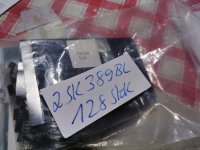
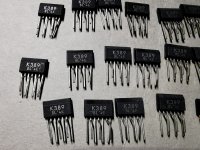
For Sale Toshiba Dual 2SJ109BL & 2SK389BL
I've got a substantial quantity of Toshiba 2SK389-BL & 2SJ109-BL Pair JFETs to sell
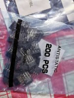
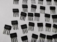
These are the genuine Toshiba Dual J-Fets. I've posted some pictures below from the 2SJ109BL from the 2SK389BL. Bought from Spoerle Electronic (Evertiq) a Toshiba Distributor.
50 piece 2SJ109BL: 16€/piece
14 Pair available 2SJ109BL & 2SK389BL: 26€ Pair
Take a look at the UGS-muse preamp GB ( UGS-muse preamp GB)
The price is excluding PayPal and shipping fees. You can refer to the photos as attached. Shipping only with registered mail. PayPal is accepted buyers needs to pay the additional PayPal fees from 4% and only with PayPal confirmed shipping address!!.Shipping prices are different depends on the country. Preference and priority is given to buyers from the EU, to prevent the damn paperwork for shipping but I can send worldwide but it takes a bit time to organize it. Only Register Mail using FINLAND Posti.
No Customs declaration is required for EU countries. For goods delivered outside the EU, i need to attach documentation required for Customs clearance. Correct Shipping costs need to check in the local Post office.
It is between 14,50€ EU and worldwide 19,50€ up to 250 gramm.
regards
Walter
Attachments
LM3866 mute circuit - control with microcontroller
- By duanestorey
- Chip Amps
- 12 Replies
Sorry if this is a remedial question - but does anyone know or can recommend a simple circuit for controlling the LM3866 mute circuit using a microcontroller with a 3.3V output voltage. If the mute was controlled with a positive voltage, I wouldn't have an issue, but I'm unsure how to control the negative voltage using a positive high signal from the microcontroller. It seems like it needs to sink more than 0.5ma of current to disable the mute.
If anyone has any suggestions, please let me know. thanks.
If anyone has any suggestions, please let me know. thanks.
Newbie
- By SanMan70
- Introductions
- 1 Replies
Hello all. I repair vintage audio as a hobby and look forward to getting and giving advice on old gear. Big Sansui guy. Bit occasionally work on newer stuff from the 80’s and 90’s. Thanks in advance to all who chime in. Cheers!
Techinvoke New Member
- By Techinvoke
- Introductions
- 1 Replies
Hi all,
This is Techinvoke and I am excited to share today that I am joining the DIY audio Community team here as a new member
First of all, I want to say it’s a privilege to be part of a site that includes professional electronics engineers, PCB designers, and hobbyist like me
I come from India and yes, we are as a country developing in many fields however the DIY electronics with in India is still lagging behind mainly because most of the components are not available due to various reasons. I am here as someone wanting to learn and also share circuits and ideas with in the limited experience and knowledge I have. Once again thank you so much
For Sale OHMITE - L0144 - Rheostat. 8 Ohm, 1.77Amp 25W.
NEW LOWER PRICE
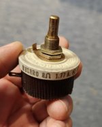
Hi. I have a box of these rheostat (10 units), I think they are NOS, never used!
They were selling for more than 62.50U$ new and 43U$, asking 10U$ each + shipping and paypal 3.5% fee
I'll make a deal if you get them all!
Great application for them is as a Heater Noise Nulling control on DHT Tube, as the 300B!
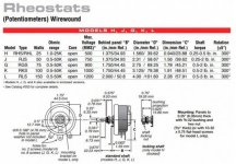
OHMITE - L0144 Rheostat.
Resistance: 8 Ohm.
Power: 25 watt.
Amperes: 1.77Amp.
Model H.
Mount: Panel, bushing.
Dimensions: 1.566" D x 1.075" behind panel. threaded bushing: 3/8" x 0.515" long.
Shaft: 1/4" D x 0.5" long.
Contacts: Solder Terminals.
Alternate: RHS8R0
Made in USA
Hi. I have a box of these rheostat (10 units), I think they are NOS, never used!
They were selling for more than 62.50U$ new and 43U$, asking 10U$ each + shipping and paypal 3.5% fee
I'll make a deal if you get them all!
Great application for them is as a Heater Noise Nulling control on DHT Tube, as the 300B!
OHMITE - L0144 Rheostat.
Resistance: 8 Ohm.
Power: 25 watt.
Amperes: 1.77Amp.
Model H.
Mount: Panel, bushing.
Dimensions: 1.566" D x 1.075" behind panel. threaded bushing: 3/8" x 0.515" long.
Shaft: 1/4" D x 0.5" long.
Contacts: Solder Terminals.
Alternate: RHS8R0
Made in USA
Attachments
Easy way to bridge an amplifier
- By vilfort
- Analog Line Level
- 6 Replies
A while back there was a discussion on this forum about an easy way to bidge a dual channel amplifier. No need for special phase splitter/turner boards. No need for changes to the internal wiring of the amp to be bridged. If you are like me, you likely have several amps laying around that you would like to bridge - just to hear how it sounds. If so, here is some good news: all you need is a pre-amp with a balanced output. Then create a quick interconnect that takes the in-phase signal (+) and the out of phase signal (-) and feed that into the Right and Left input RCA's. We are assuming that the preamp here has a volume control and that we have 2 identical amps that we can bridge for each channel.
As it turned out, I have a DAC with balanced output and 2 HAFLER 200's that would work for this experiment. All I needed was to create the interconnect:

That's it. Here Pin 1 is common ground. Pin 2 is (+) and Pin 3 is (-). (+) to one channel and (-) to the other. The speaker is connected bridged between the two positive output terminals of the power amp. Essentially the amp is running with each channel amplifying each leg of the balanced signal.
So how does it sound? - Well that is the most surprising: the old HAFLER 200's sound more alive than ever! Trumpets and saxophones have more bite. And I hear details on old familiar tracks that only the best amps manage to bring out. The Haflers already have good specs even by today's standards. Re-capping helps as well. But this inexpensive bridge interconnect brings them to a new level. I cannot explain it. Why? Common mode rejection of some left-over distortion?
If you have any idea why this is happening, please post your thoughts. Or if you just want a fun and easy project for the holidays, this might be what you have been looking for.
Have fun.
As it turned out, I have a DAC with balanced output and 2 HAFLER 200's that would work for this experiment. All I needed was to create the interconnect:
That's it. Here Pin 1 is common ground. Pin 2 is (+) and Pin 3 is (-). (+) to one channel and (-) to the other. The speaker is connected bridged between the two positive output terminals of the power amp. Essentially the amp is running with each channel amplifying each leg of the balanced signal.
So how does it sound? - Well that is the most surprising: the old HAFLER 200's sound more alive than ever! Trumpets and saxophones have more bite. And I hear details on old familiar tracks that only the best amps manage to bring out. The Haflers already have good specs even by today's standards. Re-capping helps as well. But this inexpensive bridge interconnect brings them to a new level. I cannot explain it. Why? Common mode rejection of some left-over distortion?
If you have any idea why this is happening, please post your thoughts. Or if you just want a fun and easy project for the holidays, this might be what you have been looking for.
Have fun.
Crossover design: How low is too low impedance?
I'm wrapping up my first 3-way crossover design and am looking at the impedance curve of the system.
How low is too low impedance?
And what is the significance of phase angle?
Any other issues I should be concerned with on this chart?

How low is too low impedance?
And what is the significance of phase angle?
Any other issues I should be concerned with on this chart?
Pass amp for ProAc Response 2.5?
Hello.
I'm thinking about building a Pass amp. Rumor has it that my speakers very much enjoy being driven by tube amps, but I'm not quite there yet. I built a pair of the Redux Amp Camp Amps over Thanksgiving and had a nice time.
From looking around here, seems like the Aleph series is closer in sound to a tube amp, so I'm leaning that way, but thought I would ask y'all. Please correct me if I'm wrong.
The speakers are the ProAc Response 2.5. 86dB/W/m, 8 ohm. The room is not large, but not small, and I've gotten the room to start sounding pretty good. Currently using a Naim Nait XS, 60 W into 2 at 8 ohm. Using a Bluesound Node as source / DAC.
Listen to all kinds of music, but not much 'hard rock.' Listening to Norah Jones' album "...'Til We Meet Again (Live), I really like the openness, transparency and clarity of the instruments. Beck's "Hyperspace" also gets some listening. For examples...
Depending on which SPL app I use, at the listening seat, at the loudest volumes, can be mid 70s or mid 80s dB... Suffice it to say, if I lived in an apartment, I would have some upset neighbors.
I really like the sound that I get from what I've got. It was suggested that I get a separate power supply for the Nait; the flat cap or high cap. I'm just thinking about trying something different before doing that...
Thanks for your input.
Dave.
Notch for Purifi PTT6.5X08-NFA-01
I am currently building a MTM tower with Purifi bass and Satori beryllium tweeters, discussed elsewhere here. But advice would be welcomed about a notch filter.
The bass driver is good and may not need a notch; I plan to try it with and without.
I have seen Lars's excellent article about notches for the NAA version, with a notch in series with the driver:
0.22mH, 4.2uF, 100ohms all in parallel. To be clear I call this a parallel notch.
I use 'series notch' to mean components in series, with the total cct then in parallel with the woofer.
I'm new to all this so I may be wrong, but I favour the parallel notch for two reasons.
First, Lars suggests it is low distortion.
Second, I have a low power SET amp. The series notch seems to work by taking extra current to drag the signal down, which may not be good with my low current amp?
The parallel notch seems to work by blocking the undesired frequencies, seems kinder to the amp?
Anyway, my case.
As I have low power and want high efficiency, I am looking to minimise the insertion loss of the filter, and I therefore guess at the following instead of Lar's values.
0.1mH, 15uF, 15 ohms all in parallel.
This gives just over 4kHz, which is where this driver has a peak. The peak is not great so 15 ohms resistor seems to give enough filtering. Result looks good in Xsim, as well as having less of a peak, the little that remains is now 5dB further down at about -25dB. Very small loss of sensitivity, but I think the main series inductor can be reduced by 0.1mH (to restore the same BSC) which should restore the sensitivity.
Looks good to me, but what do I know.
Any advice welcomed. The crossover in general will be discussed elsewhere.
Search Conversations
- By KevinHeem
- Forum Problems & Feedback
- 7 Replies
Is there a way to search in "Conversations"? I must admit I haven't spent much time trying on my own.
New Member
- Introductions
- 1 Replies
Hi,
I'm a new member and have moved from making kits to trying to make other designs I've found here on DIY audio. I'm trying to ask questions now on the site so I'm trying to get posting privileges. Though I've been a lurker for a while.
I'm a new member and have moved from making kits to trying to make other designs I've found here on DIY audio. I'm trying to ask questions now on the site so I'm trying to get posting privileges. Though I've been a lurker for a while.
My introduction
- By Gtamp23
- Introductions
- 1 Replies
Hi. Been using and from time to time working on transistor and tube amps for many decades. Biggest accomplishments an early 70’s Marshall 50w tremolo amp that is now SO sweet. Also an early 50’s Flot-a-tone accordion amp. Currently dealing with a HealthKit aa-1640. Saw a post about said amp so I joined the group
RCA interconnects - your collection and making your own
- By Miller-8
- Everything Else
- 8 Replies
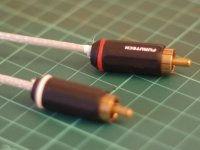
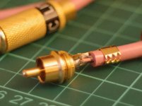
I have collected quite a few over the last 3 decades. Taken some phones here - the ones with the Furutech plugs are home made with silver cable, but I think I superglued them rather than soldering so I need to redo them (made them 20 years ago.
The pink cable is Sonic Link Silver Pink from about 1996
The pink cable is Sonic Link Silver Pink from about 1996
Attachments


Bi-amping an old pair of Polk Monitor 60
Greetings, friends. I've been aware of Bi-Amping since I was a broke teenager with Hi-Fi dreams. I still don't have a fancy amp with a Bi-Amp button, but I do have a DSP-enabled Class D amp, DIY of course, and a small single-ended EL84 amp, also DIY. The DSP is from 3e Audio and is running Sigma Studio software, of which I am mildly proficient.
Speakers in question are Polk Monitor 60. They're cheap and old, but the bass is nice and there's dual binding posts on the back for Bi-Amping.
The plan is to use the DSP as an active crossover and use the class D amp to drive the lows and the EL84 amp for the highs.
I can't find any info on the crossover frequency for these speakers. Google searches have revealed 2,250Hz as a possible number, but that seems high. I also can program a large overlap, or even implement different crossover curves, if appropriate. But I don't really know what any of that means, so any advice would be welcome.
Thanks for taking a look!
w
Greetings from Austria
- By pheliks
- Introductions
- 1 Replies
Hello, my name is Felix. I have lived in Austria for several years now, and statistically I have about half of my life still to live. Well, maybe a little less. So what to do with it? When I made a breakout board to "hack" my vacuum robot recently, I sort of rediscovered the fun in making electronics. I did attend some courses on basic electronics, soldering etc. as a kid, but had not dabbled in the field for decades until the robot project.
Now I am contemplating building a valve amplifier and a phono preamp for my private stereo system, maybe a solid state amp for the living room, and whatever else might come to mind. Of course, the actual reason behind all this is simply that I need a good argument for finally buying that cool oscilloscope. 😉
I have been reading on this forum for some time every now and then for some HiFi related info. Thanks to everyone who contributes to the wealth of knowledge to be found around here! Now I am really looking forward to the "DIY" part of the story, and maybe one day I will also be able to contribute to the collective wisdom.
Cheers!
Felix
Aging of foil and electrolytic capacitors in vintage crossovers - measured vs. factory values with age
- Multi-Way
- 32 Replies
Hello,
This is my first post on this forum, so first of all I would like to greet everyone. Here's what brings me here this time 😉
My speakers (ReVox BX-350) will soon be 50 years old, it's time to check the crossovers 😉 Since I already have experience with the renovation of ReVox Emporium B speakers and I don't want to "modernize" unnecessarily what is original and works, I have a few questions for you:
1) Has anyone of you unsoldered the old foil capacitor with plastic housing from the 70's crossover (in the ReVox BX-350 crossover it is Wima MKS 4 6.8 uF 100 V) and measured its capacitance? I ask because these foil capacitors in crossovers are considered "eternal", but during a recent repair of a home cinema projector I discovered that the foil capacitors installed there had lost 50 percent of their capacitance after 15 years of operation. If such a loss occurred in the speaker crossover, it would mean a very significant change in parameters and characteristics. To measure a foil capacitor in BX-350 speakers, you first need to unglue and desolder it, which can destroy the capacitor, because the glue is very strong. Please write if any of you have removed such a foil capacitor from any old speaker crossover and measured its capacitance.
2) Do you know of any chemical that dissolves the glue that is used to glue capacitors to the board in speaker crossovers? Maybe toluene would work - it is used to unglue speaker membranes from foam and rubber suspension?
And I will also share my experience with replacing electrolytic capacitors in other Revox crossovers. When my other speakers - Revox Emporium B - started giving strange results in the characteristic measurements in the midrange speaker range, I decided to start by replacing the capacitors in the crossover. Unfortunately, to measure their parameters, you have to unsolder and unglue them, and there was a lot of glue and it was so strong that ungluing required destroying the capacitors (bending the metal casing). Fortunately, the housings remained sealed and it was possible to measure the capacitance. And now I will share the measurement results 😉
Emporium B are about 35 years old, 3-way, closed cabinet speakers. The capacitors removed from them had identical or better parameters than the new Mundorf capacitors with smooth foil. Capacitance, ESR, Vloss - everything was fine! The only thing I noticed was that both the new and old capacitors had a much higher capacitance than the one given on the housing, by about 15 percent. So replacing these capacitors - and they were very difficult to obtain and very expensive - turned out to be completely pointless. The problem turned out to be not the crossover, but the hardened rubber suspension of one of the midrange speakers, as a result of which the resonance of this speaker shifted into the range of its operation in the speaker column.
Maybe someday I will share the Emporium B renovation process in detail, I have a lot of photos and it was a very interesting adventure - I can say right away that the greatest effect was achieved by thoroughly sealing the housing and the cable passages inside it (multi-chamber cabinet). For now, I'll leave the questions and invite you to the discussion 😉
And actually, this is another interesting topic related to crossovers in vintage speakers, designed without computers. Since almost every bipolar electrolytic capacitor, whether new or old, has a larger capacity than the one written on its housing... Wasn't it by any chance that the designers of these speakers selected electrolytic capacitors according to their actual capacity, and not the one written on the housing? Because if so, then considering an old capacitor, which instead of 15 uF has 18 uF, as "worn out" makes no sense. I think this question is quite reasonable, especially since new electrolytic capacitors also have higher capacities than the manufacturers' data. Perhaps the designers assumed this higher, actual capacity for calculations.
Best regards,
Mike
Broken circuit board Vox AC4C1
- By lmatt6285
- Instruments and Amps
- 8 Replies
Hey all,
I was a heavy handed when reconnecting a wire harness, and I damaged the some of the connections on the circuit board (Traces?) I have ample free time right now, so, I'd like to try to fix it.
Currently, I have scrapped off some of the resist from the remaining traces, and I've soldered small jumpers from the exposed copper to the original connection.
Still not working. Is there anything I'm not thinking about?
Help! Myryad mxa 5150/7150? bias ?
- By bonesbiggis
- Solid State
- 0 Replies
Someone know where to find service manual for this amp ?
6 x150W
2x80W
6 x150W
2x80W
Attachments

VTL TL2.5 preamp remote poor range.
- By mobyd
- Tubes / Valves
- 4 Replies
Have one where the IR remote works of, but only up to around 2 feet (0.6M). Batteries are good. Anyone met this and have a fix?.
Have tried replacing sender IR LED - did not help.
Have tried replacing sender IR LED - did not help.
Making AC rectifier using smart diode controllers. Is it bad to have voltage fluctuations at the input of regulator ?
- By Anatolii_A
- Electronic Design
- 1 Replies
Hi ! Is it bad to have some slow voltage fluctuations in range of 0.5V at the input of linear regulator if it is far away higher from output voltage + dropout ?
Parasound HCA2200II Troubleshooting
- By jsleonardo
- Solid State
- 7 Replies
Hi diyAudio,
I have Parasound HCA2200II and recently had issues that started with the cracking sound on Right Channel. I removed any speaker due to high probability of damaging the speaker.
When I am verifying the schematic which I have, I found that the R225 is measuring 20K ohms instead of 47K.
Bias resistors are railed voltage at +/-77V on the Right Channel while Left is around 25mV.
I am inclining that there is/are bad components on the driver board.
I also noticed sparkling on the R217 on the PCB trace when powered-up but this is gone now. I've checked the Q201-202 and Q203, they looked okay when compared with Left Channel.
I am attaching the schematic I found in the web.
Thank you in advance for the help.
Attachments
For Sale STC 3A/107A tubes
- By Geluidloopt
- Swap Meet
- 3 Replies
I have 5x NOS 3A/107A for sale, these are the electrical equivalent of WE 4019A
DHT, gain of 7, ideal as driver or preamp tube
I also have the sockets for these
Asking 70€/piece, 120€/pair, 250€ for all 5
Will ship worldwide
DHT, gain of 7, ideal as driver or preamp tube
I also have the sockets for these
Asking 70€/piece, 120€/pair, 250€ for all 5
Will ship worldwide
Attachments
New guy
- By Curtisdiy
- Introductions
- 1 Replies
Howdy,
I'm just an audio DIY guy, looking to parasite some knowledge. Past projects include a pretty spiffy headphone amp, a 3-way digitally crossed over speaker system, and a bit-perfect, gapless digital playback system (done 20 years ago, before they were commodity.)
Now seeking advice in resuscitating an old Aragon 4004 that is too old to remember the words, and now hums.
Cheers!
4-6 channel input selector IC
- By duanestorey
- Analogue Source
- 0 Replies
Anyone have any thoughts on what some of the best options are for a four to six channel input selector IC? I was using an I2C chinese one, which worked ok, but seemed to always inject a little I2C noise into the audio whenever it received data. I'm looking to replace it with something a bit more modern and reputable.
I currently have a design based on a NJM2750 part, but I think it's a bit old (might still be good though). I need more than four inputs though, so I've had to daisy chain two together.
Anyone have any other thoughts on options to look at?
Thanks
I currently have a design based on a NJM2750 part, but I think it's a bit old (might still be good though). I need more than four inputs though, so I've had to daisy chain two together.
Anyone have any other thoughts on options to look at?
Thanks
B&G RD40 ribbon replacement driver
- By Tubenstein
- Planars & Exotics
- 1 Replies
Hello!
Who offers replacement driver of B&G RD40 ribbon driver?
Thank you!
Who offers replacement driver of B&G RD40 ribbon driver?
Thank you!
Narrow Subwoofer Driver Location
- Subwoofers
- 49 Replies
I'm looking at making a subwoofer to pair with a set of small full-range speakers, but the catch is that the only place I can really fit it is underneath the TV cabinet, which gives me maximum ~100mm. I've found what appears to be a decent driver, albeit small, in the Peerless SLS-85S25CP04-04. My thoughts were to use a pair, and have modelled them in a ported enclosure around 4.5 - 5L, tuned to 38Hz. The plan would then be to add a LPF somewhere in the region of 80-100Hz in order to cross effectively with the full-range set.
Anyway, that's the background, but the main question I have is around the placement and orientation of the two drivers. Originally, I was thinking facing opposite walls, horizontal in terms of listening position, but this brings the magnets mighty close to the top and bottom walls (using 12mm ply). The important parts seem to be around 68-72mm on the diagrams, and the enclosure would have an internal height of 78mm max. Would this be a major issue for this application?
Second thought was having them facing up, but this introduces the associated problems with upward-firing speakers (and fires directly into the TV cabinet). It gives them a lot more room to breathe, however, though the magnet is then about 15-20mm from the base.
I've attached some images to illustrate the two options (I'm aware I've probably over-engineered the bracing, but I was aiming to have it CNC milled). The grey cylinders are an approximation of the speaker at it's widest points. The black tube is the port.
Option 1 - the "lid" would be inset, so sitting on top of the cross-beams.

Option 2

Any thoughts or obvious errors? Does it even matter if it's going to be booming straight off the TV cabinet above?
Anyway, that's the background, but the main question I have is around the placement and orientation of the two drivers. Originally, I was thinking facing opposite walls, horizontal in terms of listening position, but this brings the magnets mighty close to the top and bottom walls (using 12mm ply). The important parts seem to be around 68-72mm on the diagrams, and the enclosure would have an internal height of 78mm max. Would this be a major issue for this application?
Second thought was having them facing up, but this introduces the associated problems with upward-firing speakers (and fires directly into the TV cabinet). It gives them a lot more room to breathe, however, though the magnet is then about 15-20mm from the base.
I've attached some images to illustrate the two options (I'm aware I've probably over-engineered the bracing, but I was aiming to have it CNC milled). The grey cylinders are an approximation of the speaker at it's widest points. The black tube is the port.
Option 1 - the "lid" would be inset, so sitting on top of the cross-beams.
Option 2
Any thoughts or obvious errors? Does it even matter if it's going to be booming straight off the TV cabinet above?
new member
- By IAS1973
- Introductions
- 2 Replies
hello all who loves high end sound. i am from norway and are interested in try out diy speakers, and voigt pipes and folded horn loaded,,
also tube amps,
also tube amps,
I'm new here!
- By jaqwiline
- Introductions
- 2 Replies
I've played the guitar for the most of my life, but lately, I've had a lot of spare time, so I've been playing around with my setup and pick-ups. In the process, I soldered a component of my amplifier that needed it. However, as I was reassembling it, I pushed too hard on a cable connection and snapped a few circuit board traces. Here I am, then. attempting to determine that.
Expecting Warm Welcome, Hope everybody interect in nice way.
Thank you. 🙂
Expecting Warm Welcome, Hope everybody interect in nice way.
Thank you. 🙂
What to do with this power supply?
Hi All,
I am toying around with the idea of building a class D amplifier using ICE modules. I have (3) power supplies from some old Denon 250 watt class A mono block amps that died many years ago. The power supplies look very beefy, huge tansformer and capacitors.
Would it be worth trying to do something like this with them?
Thanks,
Axis
different length speaker cable question
- By henrylrjr
- Full Range
- 41 Replies
My setup requires 15 feet of speaker cable for the right side speaker to amp and the left side needs about 25 feet. I've read that speaker cables should be the same length, but don't know if coiling 10 feet of cable, on itself, in the bottom of a cabinet, might have its own problems. What would be the best, trouble free, setup?
Thanks

Thanks
diyAB Amp The "Honey Badger" build thread
- By Variac
- Solid State
- 5435 Replies
This thread is for people to discuss their builds, build issues, and parts for the diyAB "Honey Badger" power amp. the boards will be in the diyAudio store in a few days...
Main Thread:
http://www.diyaudio.com/forums/solid-state/192431-diyab-amp-honey-badger.html
Schematics, etc.:
http://www.diyaudio.com/forums/soli...amp-class-ab-amp-diyaudio-19.html#post2650279
To get boards go here to the diyAudio Store. There is also more info about the boards:
http://www.diyaudio.com/store/ampli...badger-class-ab-amplifier-circuit-boards.html
Dynaudio "ARBITER"/Horch Elektroakustik "POWER STAGE" internal Images wanted
- Solid State
- 0 Replies
From both power amplifiers are no images to find from a tear down (strip down) procedure.
Maybe one of the members can upload this.
In order to estimate the level of difficulty for the repair and create the circuit diagrams, such pictures would be very helpful.
Thank you very much for upload.
some URLs:
https://www.whatsbestforum.com/threads/the-dynaudio-arbiters-are-here.10048/
https://www.springair.de/en/dynaudio-arbiter-power-amplifiers/h50924
https://dynaudio.com/magazine/2016/february/the-worlds-best-amplifier-the-dynaudio-arbiter
https://inf.news/en/digital/b45011c73bbd94298b79b088c1d4004c.html
https://www.kleinanzeigen.de/s-anze...naudio-arbiter-nachfolger/1957665948-172-9506
Attachments
-
 Horch POWER STAGE (ref-ser.)-I.jpg79 KB · Views: 120
 -
 Horch POWER STAGE (ref-ser.)-IV.jpg102.5 KB · Views: 93
 -
 Horch POWER STAGE (ref-ser.)-II.jpg80.9 KB · Views: 85
 -
 Horch POWER STAGE (ref-ser.)-III.jpg64.6 KB · Views: 86
 -
 Horch POWER STAGE (ref-ser.)-V.jpg77.3 KB · Views: 112
 -
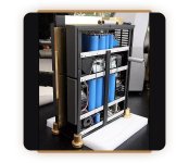 Dynaudio Arbiter Transformer ELCAPS.jpg55 KB · Views: 167
Pascal S-PRO2 Service Manual ?
- By bonesbiggis
- Solid State
- 0 Replies
someone who is sitting on a service manual or diagram for a Pascal A/S S-PRO2.
R507 = 10 Ohm ?
T503 = FMMT 718 ?
R507 = 10 Ohm ?
T503 = FMMT 718 ?
Attachments
Can differential I2S work with no receiver chip?
- By Radian
- Digital Source
- 8 Replies
Hello fellow DIYers.
Got a DDC with I2S over HDMI. As I can't find an adequate place to tap the signals on the single ended side, is it possible to only use the positive wires of the differential signal for my dac.
Signal travels at most 4 inches from HDMI plug to I2S input connector.
Klaus
Got a DDC with I2S over HDMI. As I can't find an adequate place to tap the signals on the single ended side, is it possible to only use the positive wires of the differential signal for my dac.
Signal travels at most 4 inches from HDMI plug to I2S input connector.
Klaus
Identify Power Transformers
- By tonechaser59
- Parts
- 28 Replies
Does anyone know what brand and type of power transformer this is? I have 2 New in the Box and I don't have any idea what


 they are? Can you please help me identify a power transformer? The code is: 007018-6066709
Allo USBridge Signature USB-C power connector ripped off the board
- By TherealDante
- Digital Source
- 0 Replies
Hello,
my first post….
I have no knowledge at all and I am asking because a technican asked me about the specific USB-C connector typ / name that was used on the board
for repair purpose. I would like to get it fixed again, sadly I broke it in some days after buying it used…. :0(
A nice day to all of you!
TherealDante
my first post….
Allo USBridge Signature USB-C power connector ripped off the board
I would like to ask for Information about what typ of USB-C power connector is used on the Allo USBridge Signature Board inside?I have no knowledge at all and I am asking because a technican asked me about the specific USB-C connector typ / name that was used on the board
for repair purpose. I would like to get it fixed again, sadly I broke it in some days after buying it used…. :0(
A nice day to all of you!
TherealDante
Hi, I am from germany and send greetings to all of you!!
- By TherealDante
- Introductions
- 2 Replies
Hi,
I am new here and would like to find some info and give info if wanted.
We all have the same Hobby, with different ideas about how it works…
Sound like a big field for discussions and discoverys…
All the best
TherealDante
I am new here and would like to find some info and give info if wanted.
We all have the same Hobby, with different ideas about how it works…
Sound like a big field for discussions and discoverys…
All the best
TherealDante
2SC4793 : 2SA1837 .... genuine or not?
Hello guys.... picture posted.... genuine or fake..... any ideas???
Attachments
For Sale Charcroft Z-Foil Resistors 120R 0.4W
4 pieces, asking for 35 Euros plus shipping (+ fees) SOLD
Attachments
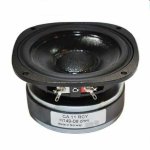
Looking for a PROAC - Tablette - Seas - Woofer - CA11RCY - 11F-GX H149
I am looking for an 8 ohm replacement woofer.
Attachments

Wilson Audio Alexandria XLF
Dear friends
God bless you all.
I have a pair of focal audiom 13wx and pair of audiom 15wx
I need an help regarding to make a clone of the wilson audio alexandria xlf
If there is anyone in this group who has a friend with the real wilson and can supply measurements of the bass enclosure and the port measurements.
Thank you all.
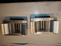
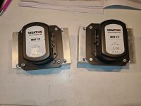
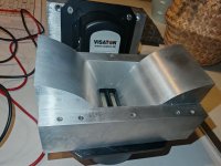
For Sale Visaton MHT-12 with CNC machined waveguides
Selling my Visaton MHT-12 magnetostat tweeter pair. They are from year 2021, I have bought them used 2 years ago. I have used them in a two different speaker projects. I have also CNC machined custom waveguides. With these waveguides they can be mounted to a square front panel hole, mounting hole size 146mm x 65mm. Waveguide depth is 65mm. Included is also 3d printed adapters to perfectly match tweeter flange to waveguide opening.
Attached is the DATS measurements, they show a slight (~0.5 Ohm) difference in impedance throughout the range. Also one of the tweeters has a slightly wrinkled diaphragm, hard to capture on photos. Anyhow, they worked both normally on both of my project speakers and showed similar frequency response (could not find the measurements from anywhere anymore though).
The price of 2 tweeters, 2 waveguides and adapters is total 300€ + shipping from Finland. This is the price what I paid for the waveguides only.
Attachments
Hi there
- By Aghawa
- Introductions
- 1 Replies
My name is Rachid , based in Montreal Canada. interested in tube audio gear and vintage speakers, specially concentric style
CEC TL2 problem and options
- By chaccone
- Digital Source
- 9 Replies
I have a CEC TL2 transport. it plays music for a short while then after that the sound is garbled/garbage. I had 2 technicians to look and try and repair but doesn't work.
Any suggestions on what I can do with the spoilt TL2? possible to replace the circuit board or something ? or should i try to sell it ?
Any suggestions on what I can do with the spoilt TL2? possible to replace the circuit board or something ? or should i try to sell it ?
Play Back and erase head
- By NDjen
- Introductions
- 1 Replies
I've just recap and re-Playback and Erase Head Revox B77
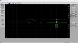
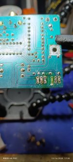
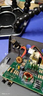
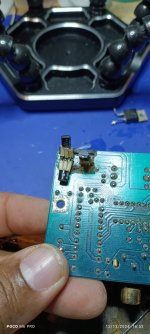
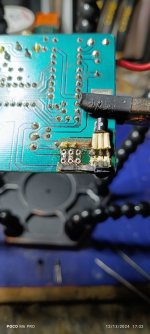
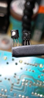
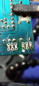
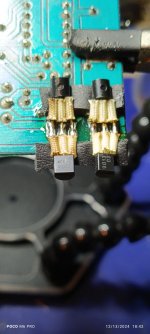
Hey guys! I'm not new here, I've been a long time stalker, but now I definitely need help.
I've seen a thread on here before about this same MCD360 Clarion Xover, that has a notoriously prone to failure power supply.
I was wondering if you guys can help me find a solution.
I was wondering if you guys can help me find a solution.
Attachments
-
 IMG_20241216_175606.jpg301.1 KB · Views: 57
 -
 IMG_20241216_175516.jpg250.9 KB · Views: 53
 -
 IMG_20241213_163404.jpg282 KB · Views: 50
 -
 IMG_20241213_165305.jpg279.2 KB · Views: 51
 -
 IMG_20241213_170251.jpg242.5 KB · Views: 48
 -
 IMG_20241213_170339.jpg244.7 KB · Views: 52
 -
 IMG_20241213_180835.jpg283.5 KB · Views: 50
 -
 IMG_20241213_184258.jpg268.7 KB · Views: 50
BC accoustic EX888.1
- By alba752
- Tubes / Valves
- 1 Replies
Hi all,
Does anybody have the schematic for a BC Acoustic EX888.1, i have one to repair and schematic will be helpfull. Thanks
Does anybody have the schematic for a BC Acoustic EX888.1, i have one to repair and schematic will be helpfull. Thanks
SnubWay Noise Defender
I have been discussing this new product for some time now during its development stages in the What’s On the Bench Thread. But I think it is time for its own dedicated thread. This usually happens when we reach a point of critical discovery or progress. Today is that point. We have conclusive data showing that a parallel plug-in filter (not a flow through filter) can reduce SMPS noise that contaminates AC mains power lines and outlets strips. The SnubWay Noise Defender is a compact module with a 120vac NEMA plug for the U.S. and Euro compatible Schuko plug for the 230VAC EU market. The 230VAC version remains to be tested.
I initially showed that the SnubWay can filter out 60kHz to 400kHz signal from a function generator imposed on an outlet strip. This was not plugged into a wall outlet or any real equipment.
Recently, I have made tests using a spectrum analyzer to look at the noise floor of the audio output of real devices to see if the noise floor can be improved by plugging in the SnubWay. I had a small SE Class A headphone amp (LuFo Lite) repaired and so I thought why not look at its noise floor. I was pleased to see that there was some 3kHz to 5kHz “grass” on the noise floor that was subsequently cut down by the SnubWay.
Above is a photo of the test in progress. You will notice the funny lampshade on the LuFo Lite (needed to cover the bright halogen bulb acting as resistive loads in the signal path). Here is the closeup of the noise floor cleanup:
Here is a photo of the MC phono line stage (Jhofland’s interpretation of a Pearl 3). It has a separate linear PSU connected by an umbilical to keep the noise low.
Here is a photo of the bench setup used to measure the phono line stage:
The noise floor of a phono line stage is one of the most critical low noise audio devices that we use in our systems. Given that the gain in these systems is around 60dB (that’s 1000 x) any sort of noise can be amplified and heard. Which is why it’s important to have as clean of a power source and power supply as possible for MC phono stages. Here is the measurement of the impact of the SnubWay for the output of the phono line stage:
Here are technical details of the testing:
Spectra were acquired using 256k length data sets acquired at 192kHz and FFTs processed with Blackman Harris 7 window function with 16 averages. Focusrite 2i4 USB audio interface and REW software. 100kHz 8th order passive brick wall filter on FFT input to prevent data aliasing from high frequency content. FFT scale: 0dB FS is 2.2vrms.
And here is what it looks like to use the SnubWay - simply plug it into the power strip:
Here is what it looks like inside:
It is a parallel network of 5 LRC filters designed using LTSpice circuit analysis and laid out on a stack of 3 two sided PCBs using premium SMT devices such as carbon film high energy pulse resistors, X2 rated safety film caps and CoilCraft shielded inductors. There is also an MOV/GDI for lightning suppression and protection from high voltage transients.
The 3D printed prototype looks like this:
The final product will be in satin anodized CNC’d aluminum with a premium Viborg acrylic base and copper wall outlet pins/blades.
We are now working on CAD models to produce the SnubWay that will look something like this:
We are still debating on final finish and color choice.
Here was an early test of the prototype as a P2P circuit and tested with a function generator noise source.
Login to view embedded media
Greetings from Canada
- Introductions
- 3 Replies
My name is Anthony Chandler. I am an English and Design Technology teacher, and my father was an electronics technician of 35 years before his death a while back. I am excited to improve my soldering skills and figuring out how circuits work. That being said, I am no expert. I have built a Bottlehead Crack, started the ACA Mini, and now have finished the ACA v.1.8, but have problems with Channel A; probably a good time to join the forum and ask for advice.
I read the posts all of the time, but I have not needed to post before. Some day I hope to build a phono preamp of some kind and whatever else comes my way.
Cheers,
Anthony
I read the posts all of the time, but I have not needed to post before. Some day I hope to build a phono preamp of some kind and whatever else comes my way.
Cheers,
Anthony
Adcom GFA 5800 oscillation
- By guy48065
- Solid State
- 8 Replies
Last week I bought a 5800 amp. During the demo in the seller's home the unit sounded good and I had no suspicions so I paid him and lugged it home.
I had read that bias & offset can be an issue with these so my test bench was it's first stop.
I noticed an oscillation on only the positive-going half of each sinewave, but only when turned up to 10 watts or more.
The amp is capable of full output from both channels, but the oscillation makes my load resistors whine.
What would cause this audible ringing at high output, only on the positive half of the signal?
The rail voltages were right on spec.
Bias & offset were adjusted to spec after a LONG heat soak. I can verify what others have written that this amp drifts until it's good & hot.
The fan speed is proportional to the temperature, and bias is very sensitive to temp. It's a delicate balancing act.
Attachments
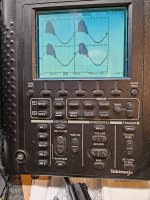
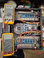
What of math for bass-treble tone control design
- By fubar3
- Electronic Design
- 20 Replies
The free National Audio Book chapter 2.4 has schematics and component selection procedures for passive and active audio tone controls. I would like to automate the procedures so there is error checking and minimal tedious keyboard work. But the National examples do not report the results for 3db calculations.
The bass-treble example in LM4562 spec prints:-
// These are the different values for example in the LM4562 spec
// fL ≈ 32 Hz, fLB ≈ 320 Hz
// fH ≈ 11 kHz, fHB ≈ 1.1 kHz
But my script prints:-
// 31.83, 289.37, 8841.94, 869.70
// Minimum treble R4 pot 292000.0
So they diverge too much for treble values. I verified my calculations with the Digikey 3db filter app ... ok
It does not matter if these maths are done with 4-byte floats or 8-byte double precision. I wrote a small C program for testing. Most software languages depend upon standard C/C++ libraries so results should be consistent across applications.
Since the National Handbook is dated 1976, the math was probably done on an ancient minicomputer with unknown software quality.
Another concern is the high value pots, 100k to 500k, used for these controls. Would they be noisy for audio circuits?
24 hour burn in of tubes
- By qguy2000
- Tubes / Valves
- 11 Replies
24 burn in of tubes prior to shipping from supplier, is this recommended or not?
Discrete phono stage, single supply.
- By nnx
- Analogue Source
- 86 Replies
In my search for a discrete phono-stage I fell over this old schematic on Paul Kemble's webpage.
It seems to originate from Wireless World, I wonder if anyone has built this one? The original is for dual 25V supply but I assume it will work for single supply too as shown on the second image.
There is no global feedback and bias is controlled by the voltage drop over 2 and 5 diodes respectively. A strange arrangement that needs to be modeled in spice and tested by experiment. The RIAA equalizer is of a passive type across the collector resistance of the first transistor.
If this works it may be an alternative to the Pacific-style jfet phono preamps, since it is based on standard bipolar transistors and not on difficult-to-obtain 2sk170's.
Please give your input and comments, thank you.
Link to schematic, at the middle of the page:http://www.angelfire.com/sd/paulkemble/sound4.html
Attachments
16 driver Ripole, what to expect?
Instead of one open baffle 18" or 21" bass driver I am investgating the possibility of 16 10" drivers in Ripole configuration.
What can I expect sensitivity wise? In theory if the drivers are wired to a 8ohm load the sensitivity will go up by 12db right? So if the drivers are 90db sensitive combined they are 102db sensitive. But I read somewhere it might be a bit less due to losses which seems reasonable. Otherwise you could build an infinitely sensitive array and blow up an entire city.
So let's say the sensitivity ends up being 99db. That means the same amp plays 9db louder with 1w@1m
But instead of one speaker rated at let's say 100w now I have 16 drivers. So intuitively I would think if I needed a 100w amp for one driver I would want a 1600w amp for 16 drivers.
I guess I want a higher wattage amp for 16 drivers but probably not 16x.
I don't know much about electronics so please be gentle with your explanations.
Need help with Tweeter replacement
- Multi-Way
- 5 Replies
Hi,
A year back I built SB 12.3 speakers and have been enjoying them for over a year. I love mid and low frequency on this speaker.
http://www.zaphaudio.com/SB12.3/
Tweeter : SB29RDC-C000-4
High is good but I want to make it better.
Is it possible to do it without measurements.
If yes, Any kind soul would look at the design and frequency response and suggest what tweeter can I replace it with. Has to be same size and metal face plate.
Load more
Projects by fanatics, for fanatics
Get answers and advice for everyone wanting to learn the art of audio.
Join the Community
508,468
Members
7,920,952
Messages