You are using an out of date browser. It may not display this or other websites correctly.
You should upgrade or use an alternative browser.
You should upgrade or use an alternative browser.
Filters
Show only:
Help neen a Crown XTI HEX file
I've got a crown xti1002 and need to reprogram the microcontroller chip. Does anyone have the XTI_LPC_01_00_08b.hex file.
Any help would be much appreciated.
Any help would be much appreciated.
Sharing this as it looks like a good deal from Taramps (haven’t used any of their products)
- By CPTX
- Full Range
- 1 Replies
As I have been banned by my better half from building any more speakers, I will not be overtly buying these…but it looks like a good deal….the specs for each driver are thoroughly published as pdf files on their website.
If anyone has used any of the Taramps products please let me know as I am very curious.
If anyone has used any of the Taramps products please let me know as I am very curious.
Hi from Holland
- By JeanPS71
- Introductions
- 2 Replies
Hi, from an avid synthesizer enthousiast, musician and HiFi lover. Looking here for some assistantce on several restoration projects.
The first will be my KEF 103.2 loudspeakers.
The first will be my KEF 103.2 loudspeakers.
Physics experiment help!
- Construction Tips
- 8 Replies
Hey y'all,
I'd to conduct an experiment using a high level of SPL (140+dB!!!!) with a variable low-frequency sound source.
My initial idea was just to run a bunch of power through a number of speakers, like a car audio subwoofer, but it sorta dawned on me that I only need a high SPL in a volume with a height of maybe a few cm and a diameter not much bigger. Would a simple transducer and a horn, within an enclosure suffice? I imagine there has to be a way to transfer high SPL to a local area because headphones and earbuds work, but outside of the SPL drop-off equation, I haven't found any good sources of info on how to design something for a small area of interest.
I'm going to need to test the SPL and was looking at sound level meters to test for high dB in excess of 130dB and they are pricey. I see some subwoofer testing ADC device that goes for 300, but I worry that their measurement area isn't precise from one area of interest to another. Any advice on how to actually measure SPL from cms to cms?
Some ideas were to just measure pressure and convert that into SPL?
Thanks for taking the time and I'm looking forward to learning more about audio device construction!
Hello Folks
- By MarknJapan
- Introductions
- 1 Replies
It's good to meet you all! I've been a music lover all my life, but in the last decade I've gotten into jazz, OTL amps and high end headphones. I'm retired, and I've barely dabbled in electronic DIY, but I figure a Pass Whammy might be a good place to start. I hope I haven't bitten off more than I can chew, but I've read through the Whammy thread and I see there are a lot of knowledgeable folks there who are willing to share their thoughts, so I should be okay.
OpAmp for hypex UCD180 LP OEM
I want to increase the gain on a UCD180 LP OEM amplifier with supply SMPS400A180. Current gain is Av 13.1 dB And I could wish for 25-26 dB. I want to boost with a suitable OpAmp.
Which distortion is better?
- By Rwan
- Solid State
- 4 Replies
For Sale Dynaudio D-28/2 Tweeter
- By TheFinisher
- Swap Meet
- 3 Replies
£80 + p&p
Woofer ID plate and square diaphragm
- By AlexisBxl
- Subwoofers
- 0 Replies
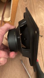
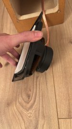
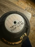
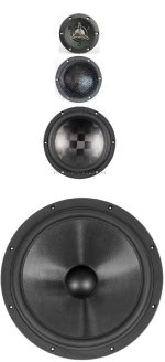
Hello! I receive a complete professional cimema audio system and i try to id the woofer inside the mid-high speaker.
As you see on pictures they are five of them on each speaker.
Diaphragm is plate and square.
If anybody as ever see those diaphragm who were popular as the sony ap series in japan in 90s let me know.
Thx to all readers and contributors.
As you see on pictures they are five of them on each speaker.
Diaphragm is plate and square.
If anybody as ever see those diaphragm who were popular as the sony ap series in japan in 90s let me know.
Thx to all readers and contributors.
Attachments


reasonable DVM?
- By BeardyWan
- Equipment & Tools
- 9 Replies
I have a Fluke 75 that has been totally reliable for years - which is a preface to saying I have no idea about current offerings... I am looking for a DVM for matching transistors. I have a bench supply that will provide a constant current and my fluke will display to .001V and give a repeatable stable reading, but I wanted a bit more resolution.
I did buy an Aicevoos 6000 count meter but it appeared to function like an underdamped random number generator. So it went back.
Any recommendations for something <$80?
cheers
I did buy an Aicevoos 6000 count meter but it appeared to function like an underdamped random number generator. So it went back.
Any recommendations for something <$80?
cheers
For Sale QUAD 99 preamp , Boxed, Remote Control
- By TheFinisher
- Swap Meet
- 2 Replies
In perfect working order
Original box and packaging
Original remote control
Used daily
Uk based
£300 + shipping


Original box and packaging
Original remote control
Used daily
Uk based
£300 + shipping
For Sale Morel MDT-30 Tweeters ( pair )
- By TheFinisher
- Swap Meet
- 1 Replies
£150 + p&p
I’m in the UK
For Sale KEF T27A ( SP1032 ) Tweeters
- By TheFinisher
- Swap Meet
- 2 Replies
T27a Constructor series
Excellent cosmetic condition and perfect working order.
£120 + p&p
For Sale Sawafuji Dyanwave or Dynapleat midrange drivers
- By TheFinisher
- Swap Meet
- 2 Replies
Working perfectly and in excellent used cosmetic condition .
£80 + p&p
I’m in the UK


£80 + p&p
I’m in the UK
Complete and Tested LT4320 based active bridge rectifier
SOLD SOLD SOLD
Info on the boards :
https://www.diyaudio.com/community/threads/lt4320-based-active-rectifier.336572/page-78#post-7729619
MOSFETs used are TPH4R008NH, which is one of those listed by Prasi
https://www.mouser.sg/ProductDetail/Toshiba/TPH4R008NHL1Q?qs=sA3qAAQcQeEIWvkYMlVV6Q==
I have not installed the LED, which i deem as redundant. C1 and C2 are not really necessary but I installed C1 (1uf x7R ceramic cap) anyway. Some well-experienced member has also reflected that the caps on board is not really necessary unless your reservoir cap is some distance away.
Some members who were interested in the empty boards I posted for sale expressed some worry about soldering the smd MOSFETs.. so I did up a pair with the hope of clearing my extra boards.
My listing for empty boards here:
https://www.diyaudio.com/community/threads/prasi-lt4320-based-active-rectifier.416460/
The pair of boards + shipping to you ( registered + tracking) = USD 42
Paypal FF only please.
Replacement for L272M in CDM-2?
- By tubee
- Digital Source
- 4 Replies
Hello to you all
I have searched a long time on chipmakers-sites for a replacemant for the L272M double opamp, because the L272M has a lousy 1V/uS slewrate.
Difficult to find, the L272 is capable of 700mA too, and selected for minimal offset in CDM-2.
The higher slew rate wil probably reduce reading errors.
Anyone a suggestion?
Tubee: note:
Want to learn about SMPS building
- By sweetperfume
- Power Supplies
- 2 Replies
Hello members,
I want to learn building smps. I used to work with my father who did all the things. He passed away. Now i am left with the business.
I have learned alot from my father about amplifiers and doing well in that section. But i don't get a thing about power supplies.
He taught me a little about dcdc boost converters. But i don't know anything about push pull type convertors.
I hope someone will be wanting to teach me everything including the basics.
I am already accustomed with repairing of these type of converters but don't know how to build an efficient one.
I have tried to copy push pull types from other car amplifiers but they don't work as intented on heavy loads. Till 200w i got these to work but above that i don't think i could do anything without tutoring.
Basically, i am a newbie. I hope some of you guys can help me out with every lessons.
From calculations of dead time, transformer construction, inductors, mosfet selections, everything.
I hope to learn from you people.
Thanks in advance
Contact for Ovidiu Popa aka syn08?
- By jan.didden
- In Memoriam
- 24 Replies
Hi guys, I'm trying to get in contact with Ovidiu Popa, who was a member here under the monniker syn08.
He hasn't been active for a few years and cannot be PM'd. Anyone has a contact for him?
Edit: My face is red - I have been informed that Ovidia has passed away. Apologies to his famuly and close friends.
Interestingly, his website is still accessible so someone apparently keeps on funding that.
Jan
He hasn't been active for a few years and cannot be PM'd. Anyone has a contact for him?
Edit: My face is red - I have been informed that Ovidia has passed away. Apologies to his famuly and close friends.
Interestingly, his website is still accessible so someone apparently keeps on funding that.
Jan
Need advice on Pmc ob1i woofer # 13534 i
- By jmasi07
- Introductions
- 1 Replies
I have disassembled the woofer and see picture for nomenclature and reference any advice please as you brand and alternates please thanks in advance
Attachments
Greetings from Colorado
- By re5513
- Introductions
- 1 Replies
Hello all. I just was approved for this group and was given instructions to post here to provide an introduction.
I am an electrical engineer by training and have spent the majority of my engineering career with HP (including Agilent and now Keysight). I've worked on multiple product lines ranging from microprocessor emulators to logic analyzers to oscilloscopes. In my day job I'm working with other measurement scientists on test methods for 128GBit/s to 1.6TBit communication standards. Funny, in my spare time, I really get excited when I see nice flat performance out past 20KHz. They are really quite different worlds. Nevertheless, I've been building out my personal portfolio of audio band test equipment and have spent time most recently engaged in high-end cassette deck restorations. It was my era so I'm still fascinated by how some of the TOTL machines respond to alignments, component updates, and recalibration.
Cheers.

Hypex FA503 to drive dual 15" subs in Ripole vs Drivecore XLS2500
- By brandon hook
- Subwoofers
- 1 Replies
I've been exploring the idea of building fully integrated active tower speakers using Hypex plate amplifiers. I've been driving the subwoofer section lately with a Drivecore XLS2500 amp, with Dual 15" RSS390HF-4's in parallel (2 ohm load). In this configuration, I require between 600 and 1000 watts to meet my needs.
The Hypex FA503 offers 500W + 500W + 100W, which seems like a good candidate. My plan is to:
The Crown DriveCore XLS2500 claims a damping factor of >200 at 8 ohms (10-400Hz), which translates to an output impedance of 40mOhms, below 400Hz. In contrast, the Hypex amp has an output impedance of ~1mOhm (<1kHz).
I assume wiring resistance adds to the denominator to give DF = Load impedance / (amp output impedance + wiring resistance). My calculations follow:
The Hypex FA503 offers 500W + 500W + 100W, which seems like a good candidate. My plan is to:
- Use the two 500W channels to drive the dual 15" subs in my ripole (25-110Hz). (500W into 4Ohms, each channel)
- Use the remaining 100W channel to feed a 3-way passive crossover for the midbass, midrange, and tweeter section (110Hz-20kHz).
Power Requirements
I’ve conducted measurements on the upper 3-way drivers during extreme listening sessions (painfully loud) and found that they draw less than 50W. Based on this, I believe the 100W channel is sufficient for the 3-way.Pros/Cons of an Integrated Approach
Pros:- Cleaner appearance
- Higher damping factor
- Built-in DSP
- Remote control options
- Higher cost (I already have the DriveCore amp for the subs and several stereo amps for the 3-ways above).
Damping Factor: Does It Matter?
This brings me to my main question about damping factor. If ever there were an application where damping factor mattered, I would expect it to matter most on a Ripole, without any meaningful air spring restoring force acting on the cone.The Crown DriveCore XLS2500 claims a damping factor of >200 at 8 ohms (10-400Hz), which translates to an output impedance of 40mOhms, below 400Hz. In contrast, the Hypex amp has an output impedance of ~1mOhm (<1kHz).
I assume wiring resistance adds to the denominator to give DF = Load impedance / (amp output impedance + wiring resistance). My calculations follow:
- Integrated amps (Hypex): ~363 DF installed, assuming 2ft of 14ga cable (10mOhms for wiring, 1mOhm output impedance).
- External amps (Crown): ~22 DF installed, with 10ft of 14ga cable (50mOhms for wiring, 40mOhms output impedance).
My Questions:
- In the frequency range of 25-110Hz, would a damping factor difference of 22 vs. 363 produce an audible difference?
- What measurements could I run to visualize or quantify the potential audible differences?
- Is there a practical limit where damping factor improvements no longer translate into real-world benefits?
- Has anyone actually measured the output impedance of the DriveCore amps? (Delta load method?)
Review of commercial application of Alpair 5.3
- By planet10
- Full Range
- 7 Replies
https://darko.audio/2025/01/lindemann-move-mini-review/
Srajan got the Copper (not Gold) right but it is officially 3” driver not 4”
The widly spaced AZMT seems extraneous to me.
https://lindemann-audio.de/products/move-mini/?lang=en
dave
Sansui 1000EA Glass front
- By Tom7227
- Tubes / Valves
- 4 Replies
Any chance (low expectations), that someone has a one. Or a possible place to locate for a reasonable price. Bought this from Ebay, and determining weather to return for a refund .
Thanks
![IMG_E1445[1].JPG](https://www.diyaudio.com/community/attachments/img_e1445-1-jpg.1409282/ "IMG_E1445[1].JPG")
Thanks
Dual Coil, 2 amps?
- By freon2
- Subwoofers
- 4 Replies
Will I get more dB if I use 2- FOSI M01 sub amps to power the 2 voice coils in a dual coil subwoofer?
Audio-Precision System One repair
- By LabGuy
- Equipment & Tools
- 5 Replies
Hello to all members.
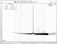
I'm repairing an AP System One that has out of spec distortion in part of the of the audio spectrum. I checked with another THD analyzer that the problem is really in the generator and I removed all the add on options (IMD, etc.) to be sure they were not at fault. To be sure I replaced all electrolytic and tantalum capacitors on the generator and power supply without any improvement. In most of the spectrum the distortion is 0,002% or less, jumping to 0,004% from 205 Hz to 2047 Hz, when the "1 KHz" band is selected by U352A pin 1.
Since distortion is OK in all other bands I would say that the two MDAC hybrids are OK and also that the three OP amps in the oscillator loop are OK too.
Have you seen something like that before ?
Thank you !
iPod Touch 4th Generation - Wolfson DAC
- By Sam Ash
- Everything Else
- 80 Replies
I am still using the iPod Touch 4th generation which sits in a simple docking station that enables connection to a processor via RCA out. I absolutely love the sound of the Wolfson DAC in the iPod which to me; is better than than engaging the higher end DAC in my processor via an NVIDIA Shield and Spotify Connect. The former sounds much more dynamic and interesting, the later sounds flat and subdued. After researching this on the net, I'v come to learn that a lot of people loved the musicality and dynamism of the Wolfson DAC. Furthermore Apple engineers chose this DAC for the early iPod range and that alone says something about this DAC.
I have some questions:-
1. Are the classic Wolfson based DACs still available in an outboard / standalone version?
2. Is there a standalone DAC out there that comes very close or is identical to the Wolfson DAC?
3. Is there a way to turn the iPod into a standalone DAC? - Has anyone managed to do that?
I love the efficiency of Spotify Connect but I want to maintain the sound signature of the iPod Touch Gen4. Just to clarify, the EQ on my iPod has been deactivated.
To enjoy music, I have to physically copy the music files on my iPod which is becoming a bit frustrating.
Constant Directivity without Horns or Waveguides
- Multi-Way
- 49 Replies
I recently made a fascinating accidental discovery: By choosing unconventional crossover frequencies and baffle dimensions, you can achieve Constant Directivity using regular woofers and dome tweeters - without waveguides, horns or dipoles.
I call it Zero Horn Constant Directivity (ZHCD). Jack Regula (@nc535) ran some simulations and helped me refine the model. First I’ll show off the end result, then I’ll explain the theory and model and give you a design guide.
Example #1: 5” 2 way with dome tweeter. Focal 5N402DB 5" woofer + Audax TW025 25mm dome. Front baffle is 8" wide.

First I tried a 1700Hz crossover which got me this frequency response at 0, 15, 30, 45, 60, 75, 90 degrees off axis:

Notice some "bunching" around 2500Hz. This bunching comes entirely from the tweeter, as the crossover is 1700. At 45 degrees off axis, the output is +4dB higher than on axis.
BUT guess what… if I set the crossover at 4900Hz I get this:

Theory (what I thought I knew about tweeter dispersion = omnidirectional below 8KHz) said this was impossible. Simple theory would predict the woofer is directional above 1K while the tweeter is not directional until 8-10K, but as you can see here, the tweeter’s directional characteristic matches the woofer’s almost exactly.
I might have just thought it was odd and shrugged my shoulders and went on, but I noticed the same thing with another smaller system – A JVC HSA1014 + Dayton ND16FA. Cabinet is 4.5” wide and 6.5” tall.

I attempted a 3KHz crossover and got similar results as my first try above (bunching around 4KHz), but then a 7KHz crossover got me this result:

This is an almost perfect Constant Directivity result above 1KHz with considerable directionality from a tiny 16mm tweeter… which I would expect to have NO directionality!
This was a big surprise. So I got curious. This reminded me of a phenomenon that I observed with the Live Edge Dipoles, which have a wide 19” live edge wood baffle and an 8” coaxial mid-tweeter. The Live Edge Dipoles have a minor but noticeable “bulge” at +/-45 degrees off axis, at about 1KHz:

On the low end, Dipoles start rolling off at λ = 2X cabinet width, and normal box speakers similarly have a -6dB Baffle Step at λ = 2X cabinet width. Lots of speaker designers know about these.
Now there are a couple of other baffle diffraction modes I don’t recall getting much attention. If you know what you’re doing, you can really take advantage of this and achieve Constant Directivity without horns or waveguides.
It turns out this +/-45 degree bulge at 1KHz in a 19” wide baffle corresponds to the 2.5KHz bulge from the 8” wide baffle, which also corresponds to the 4KHz bulge from the 4.5” wide baffle. I call this Baffle Bulge. It occurs across a range of λ = 0.5X to 1X cabinet width. At this frequency the on-axis response is the “normal” and “expected” but the off-axis response has a peak caused by diffraction from the edges of the baffle.
Then at even higher frequencies, where λ = 0.25X to 0.5X cabinet width, you get a Baffle Beam and over this octave, on-axis radiation is strong; but off axis drops off much like if you had a waveguide.
So if I draw these points on the polar plot above, it looks like this:

So this means in the 5” 2-way with 8” wide cabinet, most people would cross the tweeter at 2-3KHz fearing that the woofer will get too beamy, and has too much cone breakup. That’s what I did in my first attempt. But what I found was: Even the small 5” woofer begins to beam above 1K and then the tweeter has +4dB lobes at +/-45 degrees at 2.5KHz and the off axis response is very uneven.
Yet if I cross it over at 5K, the woofer’s natural beaming has already kicked in and is not as bad as I feared; also, the woofer’s beaming is not affected much by the front baffle dimensions; and then the tweeter is benefiting from Baffle Beam from 4KHz to 8KHz; and above 8KHz the 1” dome begins beaming naturally because of its dimensions; and viola, I get Constant Directivity behavior from 500Hz up. The combination of woofer beaming and calculated cabinet diffraction gets us almost identical polar patterns and CD behavior from woofer and tweeter alike.
Again:
In the 4.5” 2-way with 4.5” wide cabinet, the woofer’s beaming from 3-7K is matched by the tweeter’s Baffle Beam above 7K and even this tiny system gives me Constant Directivity behavior from 1000Hz up:
I’ve been designing speakers for a long time, so I’m conditioned to avoid woofer beaming and breakup and handoff to the tweeter at a low frequency. But it turns out if your woofer has well behaved gradual breakup modes at the upper end of its range, and you design the crossover appropriately (the woofer crossover on both of these was more complex than usual), you get the fantastic imaging that CD designs are known for and both of these systems are well behaved at the upper end of the woofer’s range.
So I asked Jack Regula ( @nc535 ) to run some simulations to shed light on this. All of these simulations are of a 1” tweeter only (there is no woofer in the simulation) mounted on a box of dimensions 8” wide x 13” tall.
So let me step you through the research Jack and I did. First, Jack experimented with rounded vs sharp edges, and found that an 18mm bevel on each edge greatly reduced high frequency ripple. So all the simulations that follow assume that 18mm bevel.
Secondly, asymmetry in diffraction is also desirable. The worst situation is a tweeter in the middle of a round baffle. Second worst is putting it in the middle of a square baffle. Third worst is putting it in the middle (as I admittedly did in my small 2-ways).
When Jack put the tweeter in the center of the baffle, this is the polar heat map he got:

Notice significant “Baffle Bulge” at 2.5-4KHz which we are avoiding by choosing a 5KHz crossover.
Jack moved it off center and found a really nice spot here. The red dot is the tweeter location:

At this off-center position, Baffle Beam is working for us from 4-8K and has no nasty peaks or surprises:

[Please note that Jack’s models have irregularities above 8K that are a result of not using tons of points in the calculations, to save computer time – artifacts of the simulation.]
I call it Zero Horn Constant Directivity (ZHCD). Jack Regula (@nc535) ran some simulations and helped me refine the model. First I’ll show off the end result, then I’ll explain the theory and model and give you a design guide.
Example #1: 5” 2 way with dome tweeter. Focal 5N402DB 5" woofer + Audax TW025 25mm dome. Front baffle is 8" wide.
First I tried a 1700Hz crossover which got me this frequency response at 0, 15, 30, 45, 60, 75, 90 degrees off axis:
Notice some "bunching" around 2500Hz. This bunching comes entirely from the tweeter, as the crossover is 1700. At 45 degrees off axis, the output is +4dB higher than on axis.
BUT guess what… if I set the crossover at 4900Hz I get this:
Theory (what I thought I knew about tweeter dispersion = omnidirectional below 8KHz) said this was impossible. Simple theory would predict the woofer is directional above 1K while the tweeter is not directional until 8-10K, but as you can see here, the tweeter’s directional characteristic matches the woofer’s almost exactly.
I might have just thought it was odd and shrugged my shoulders and went on, but I noticed the same thing with another smaller system – A JVC HSA1014 + Dayton ND16FA. Cabinet is 4.5” wide and 6.5” tall.
I attempted a 3KHz crossover and got similar results as my first try above (bunching around 4KHz), but then a 7KHz crossover got me this result:
This is an almost perfect Constant Directivity result above 1KHz with considerable directionality from a tiny 16mm tweeter… which I would expect to have NO directionality!
This was a big surprise. So I got curious. This reminded me of a phenomenon that I observed with the Live Edge Dipoles, which have a wide 19” live edge wood baffle and an 8” coaxial mid-tweeter. The Live Edge Dipoles have a minor but noticeable “bulge” at +/-45 degrees off axis, at about 1KHz:
On the low end, Dipoles start rolling off at λ = 2X cabinet width, and normal box speakers similarly have a -6dB Baffle Step at λ = 2X cabinet width. Lots of speaker designers know about these.
Now there are a couple of other baffle diffraction modes I don’t recall getting much attention. If you know what you’re doing, you can really take advantage of this and achieve Constant Directivity without horns or waveguides.
It turns out this +/-45 degree bulge at 1KHz in a 19” wide baffle corresponds to the 2.5KHz bulge from the 8” wide baffle, which also corresponds to the 4KHz bulge from the 4.5” wide baffle. I call this Baffle Bulge. It occurs across a range of λ = 0.5X to 1X cabinet width. At this frequency the on-axis response is the “normal” and “expected” but the off-axis response has a peak caused by diffraction from the edges of the baffle.
Then at even higher frequencies, where λ = 0.25X to 0.5X cabinet width, you get a Baffle Beam and over this octave, on-axis radiation is strong; but off axis drops off much like if you had a waveguide.
So if I draw these points on the polar plot above, it looks like this:
So this means in the 5” 2-way with 8” wide cabinet, most people would cross the tweeter at 2-3KHz fearing that the woofer will get too beamy, and has too much cone breakup. That’s what I did in my first attempt. But what I found was: Even the small 5” woofer begins to beam above 1K and then the tweeter has +4dB lobes at +/-45 degrees at 2.5KHz and the off axis response is very uneven.
Yet if I cross it over at 5K, the woofer’s natural beaming has already kicked in and is not as bad as I feared; also, the woofer’s beaming is not affected much by the front baffle dimensions; and then the tweeter is benefiting from Baffle Beam from 4KHz to 8KHz; and above 8KHz the 1” dome begins beaming naturally because of its dimensions; and viola, I get Constant Directivity behavior from 500Hz up. The combination of woofer beaming and calculated cabinet diffraction gets us almost identical polar patterns and CD behavior from woofer and tweeter alike.
Again:
In the 4.5” 2-way with 4.5” wide cabinet, the woofer’s beaming from 3-7K is matched by the tweeter’s Baffle Beam above 7K and even this tiny system gives me Constant Directivity behavior from 1000Hz up:
I’ve been designing speakers for a long time, so I’m conditioned to avoid woofer beaming and breakup and handoff to the tweeter at a low frequency. But it turns out if your woofer has well behaved gradual breakup modes at the upper end of its range, and you design the crossover appropriately (the woofer crossover on both of these was more complex than usual), you get the fantastic imaging that CD designs are known for and both of these systems are well behaved at the upper end of the woofer’s range.
So I asked Jack Regula ( @nc535 ) to run some simulations to shed light on this. All of these simulations are of a 1” tweeter only (there is no woofer in the simulation) mounted on a box of dimensions 8” wide x 13” tall.
So let me step you through the research Jack and I did. First, Jack experimented with rounded vs sharp edges, and found that an 18mm bevel on each edge greatly reduced high frequency ripple. So all the simulations that follow assume that 18mm bevel.
Secondly, asymmetry in diffraction is also desirable. The worst situation is a tweeter in the middle of a round baffle. Second worst is putting it in the middle of a square baffle. Third worst is putting it in the middle (as I admittedly did in my small 2-ways).
When Jack put the tweeter in the center of the baffle, this is the polar heat map he got:
Notice significant “Baffle Bulge” at 2.5-4KHz which we are avoiding by choosing a 5KHz crossover.
Jack moved it off center and found a really nice spot here. The red dot is the tweeter location:
At this off-center position, Baffle Beam is working for us from 4-8K and has no nasty peaks or surprises:
[Please note that Jack’s models have irregularities above 8K that are a result of not using tons of points in the calculations, to save computer time – artifacts of the simulation.]
Li-Ion Jumper Packs
- By Perry Babin
- Car Audio
- 0 Replies
When repairing or otherwise running amps out of the vehicle, does anyone here use a Li-Ion jumper battery pack?
If so, pros and cons?
If so, pros and cons?
TDA1387x8 - I/V stage w/ NE5534 - Aprox. -4.4V DC in output, why?
- By dptucunduva
- Digital Line Level
- 2 Replies
Hi all.
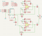
I am building a 8 ch DAC based on 4 TDA1387x8 boards. Each TDA1387x8 I/V stage is based on two NE5534 with a 1k feedback resistor (R4/R5) + 4.7nF cap (C3/C4). A 47pF cap connects pins COMP and COMP/BAL. It is basically 4 ProtoDACs with an active output stage.
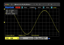
I am a computer engineer for 30+ years, but went down the software path. So electronics is not my strong... What I am trying to understand is why I always get aprox. -4.4VDC before the coupling caps (opamp output - pin 6) when there is nothing playing. If I put a 2kHz sinewave at 0db, I get aprox. 6.8V peak to peak (a little bit more than what I aimed for, need to adjust R4/R5) but the osciloscope shows that the minV is -8VDC and maxV is -1.2VDC. I.e., the signal is "centered" at -4.4VDC.
I built a single chip version (2ch only) in a perfboard and it plays just fine - after the MKP 4.7uF coupling caps (C13/C14), I get the sinewave from -3.4VDC to +3.4VDC as expected. Too early to say something about its sonic capabilities as I have just one channel pair done and the PSU built in a protoboard.
I've attached the schematics of one channel pair (1 TDA1387x8 + its I/V stage) and the oscilscope measurement.
Is it normal to have the signal "shifted" by -4.4VDC? Why?
Thanks!
I am building a 8 ch DAC based on 4 TDA1387x8 boards. Each TDA1387x8 I/V stage is based on two NE5534 with a 1k feedback resistor (R4/R5) + 4.7nF cap (C3/C4). A 47pF cap connects pins COMP and COMP/BAL. It is basically 4 ProtoDACs with an active output stage.
I am a computer engineer for 30+ years, but went down the software path. So electronics is not my strong... What I am trying to understand is why I always get aprox. -4.4VDC before the coupling caps (opamp output - pin 6) when there is nothing playing. If I put a 2kHz sinewave at 0db, I get aprox. 6.8V peak to peak (a little bit more than what I aimed for, need to adjust R4/R5) but the osciloscope shows that the minV is -8VDC and maxV is -1.2VDC. I.e., the signal is "centered" at -4.4VDC.
I built a single chip version (2ch only) in a perfboard and it plays just fine - after the MKP 4.7uF coupling caps (C13/C14), I get the sinewave from -3.4VDC to +3.4VDC as expected. Too early to say something about its sonic capabilities as I have just one channel pair done and the PSU built in a protoboard.
I've attached the schematics of one channel pair (1 TDA1387x8 + its I/V stage) and the oscilscope measurement.
Is it normal to have the signal "shifted" by -4.4VDC? Why?
Thanks!
Attachments
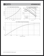
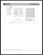
IXFN400N15X3
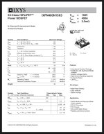
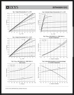
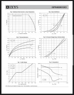
I am contemplating using a pair IXFN400N15X3 in TO-227 packaging to replace the 6 IRF244 in my Aleph 5 build, to get away from the matching issue.
On paper it seems to be impressive RDS, lower than 3 IRF244 in parallel, VDS is lower but adequate for my Aleph 5, ID 400A, Qg higher than 3 IRF244, PD 695W.
Anyone knows if this is suitable as IRF244 replacement?
If some expert here could help with designing the output stage of the Aleph 5, I shall be happy to be the guinea pig to report the outcome, with fire extinguisher on standby, of course.
Here is the data sheet.
Attachments

Semisouth R100 Circlotron?
- By woofertester
- Pass Labs
- 10 Replies
I have 2 pairs of Semisouth R100 JFETs. Having successfully breadboarded a J113 circlotron circuit, I am considering trying a point-to-point lashup of a pair of R100s in a circlotron configuration. Has anyone already tried this?
headphone dootlet i made
- By No ideas
- Headphone Systems
- 2 Replies
only thing i need to do now is to buy an better potentiometer and a pair of headphone jacks since the potentiometer is really noisy and the headphone jack dosent contact well.
Quick Sophomore Question About Resistor Voltage Rating
- By samhill
- Tubes / Valves
- 6 Replies
In vintage tube amps repairs or clones I've always used 1/2 carbon comps where called for, never gave much thought to the voltage rating as I was doing "like for like". My supply of NOS is finishing, I'm not going to bother with modern carbon comps, the tolerance is sloppy and the leads are too short anyway for repairs or building ptp. I'm looking at the KOA Speer CF carbon films, rating is 350V, is this the max voltage drop across the resistor or the value it'll see on the side feeding it?
Some companies don't give a max rating telling you to use Ohms's law for whatever resistance value you are using but as a general rule when buying batches can I assume 350v rated 1/2W resistors are fine for amps below 500V on the output tube plates, your typical Vox, Fender, Marshall, Dynaco etc?
BTW I do use 1W or 2W in the power string and will use 1W for cathode followers or on the tail of a phase inverter, and yes I should just use 1W carbon film all around but I want to stock up on 1/2s as I also play with ss and I want to try the KOAs which have a good reputation, Mouser, Digikey etc don't offer 1W KOA carbon films in many values.
Verification of speaker selection for a 4-way design
- By Yotomeczek
- Multi-Way
- 7 Replies
Inspired by a friend and his new OB, I finally decided to take the plunge on the endgame design (for me). A few years ago I was trying to figure out how to make a stable 3-way with a larger woofer and there was always something wrong...
A friend of mine has already created beautiful 4-way OB based on BlieSMa beryllium domes. I want to use slightly cheaper versions of the BlieSMa midrange dome - TeXtreme version. The whole thing is to be controlled from miniDSP Flex Eight and actively powered. Of course, someone familiar with the subject will come to help with tuning.
I'm getting ready to assemble a set of speakers and today it looks like this (almost TeXtreme team):
Bass: SB SB42FHCL75-6 - interesting loudspeaker with a stiff diaphragm - it can be extended to around 300 Hz (planned closed housing and cut around 150 Hz)
Low-mid: Satori MW19TX-8 7.5" version with TeXtreme diaphragm. (planned division 150Hz to approx. 600Hz)
Diameter: BlieSMa M74T-6 version with TeXtreme diaphragm (planned division 600Hz to approx. 3500Hz)
High: SATORI TW29TXN-B-8 version with TeXtreme diaphragm (planned division from approx. 3500Hz)
I wonder if, for highs, e.g. BlieSMa T25B-6 (Beryl) would be better? I think the 34mm BlieSMa T34B-4 would be an unnecessarily large dome (when used with a midrange dome)? It seems to me that the low-mid Satori MW19TX-8 7.5" would be a good choice. I considered the 6.5" version but it seemed too small. Maybe it's worth considering a different speaker?
Attachments
An original, high-performance complementary transistors matcher
- By Elvee
- Solid State
- 17 Replies
Transistor matchers are not uncommon: in fact they are all over the place, and generally work satisfactorily. A good example has been presented recently by Mark:
The vast majority however matches identical transistors. Complementary matchers are much rarer, and sometimes have issues:
It is possible to build something much better, whilst keeping things simple.
This matcher places the BE junctions in parallel, and biases them with two 1K resistors.
If the transistors have identical Vbe and Hfe, the circuit is perfectly balanced and the average voltage taken from the bases and emitters will sit exactly at mid-supply, and can be compared to a reference divider:

In this case, the complementarity is unperfect, the conduction of the P transistor is stronger, driving A negative wrt the reference divider.
Because of the exponential relationship between the delta-Vbe and the collector current, a tiny mismatch is easily detectable.
The Hfe of the transistors also affects the result, to a lesser degree.
You can convince yourself that the principle is sound:
Here is the jig fitted with a synthetic transistor, a sex-changed BC547B into a BP547B:

As you can see, the match is perfect.
Here are some pics of the jig in action:


To be continued....
The vast majority however matches identical transistors. Complementary matchers are much rarer, and sometimes have issues:
It is possible to build something much better, whilst keeping things simple.
This matcher places the BE junctions in parallel, and biases them with two 1K resistors.
If the transistors have identical Vbe and Hfe, the circuit is perfectly balanced and the average voltage taken from the bases and emitters will sit exactly at mid-supply, and can be compared to a reference divider:
In this case, the complementarity is unperfect, the conduction of the P transistor is stronger, driving A negative wrt the reference divider.
Because of the exponential relationship between the delta-Vbe and the collector current, a tiny mismatch is easily detectable.
The Hfe of the transistors also affects the result, to a lesser degree.
You can convince yourself that the principle is sound:
Here is the jig fitted with a synthetic transistor, a sex-changed BC547B into a BP547B:
As you can see, the match is perfect.
Here are some pics of the jig in action:
To be continued....
Attachments
TDA1540 - I2S to Offset Binary, no CPLD, no FPGA
- By miro1360
- Digital Line Level
- 121 Replies
Final verdict:
Don't build it with these logic chips and do it with my CPLD solution.
CPLD is very fast and accurate. I created open solution for all of you:
I2S to TDA1540 with CPLD: https://electrodac.blogspot.com/p/tutorial-how-to-programm-altera-cpld.html
Building TDA1540 from scratch: https://electrodac.blogspot.com/p/dac-ad1862-almost-tht-i2s-input-nos-r.html (look for TDA1540 section)
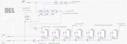
Hi folks,
my first attempt for converting I2S to Offset Binary. This format is used in the old 14-bit R2R DAC chip TDA1540.
The conversion from I2S to Offset Binary is as simple as inverting the MSB bit. It is easier said than done 😀
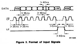
My logic is created from naked logic gates and a few shift registers. It is working for the standard I2S word in length of 64 bits (generated from well known XMOS based converters, or PCM2706/7).
Basic principle:
Converting serial to parallel - inverting bit - parallel back to serial seems be hungry for parts, so I did it very simple, simple but not perfect. There is no synchronization and maybe a hidden timing issue.
Any improvements are welcome, like stop clock operation for both channels, better timing, ...
Don't build it with these logic chips and do it with my CPLD solution.
CPLD is very fast and accurate. I created open solution for all of you:
I2S to TDA1540 with CPLD: https://electrodac.blogspot.com/p/tutorial-how-to-programm-altera-cpld.html
Building TDA1540 from scratch: https://electrodac.blogspot.com/p/dac-ad1862-almost-tht-i2s-input-nos-r.html (look for TDA1540 section)
Hi folks,
The conversion from I2S to Offset Binary is as simple as inverting the MSB bit. It is easier said than done 😀
My logic is created from naked logic gates and a few shift registers. It is working for the standard I2S word in length of 64 bits (generated from well known XMOS based converters, or PCM2706/7).
Basic principle:
- MSB bit is inverted after each LRCK edge, controlled by XOR gate + pulse
- BCK is inverted for TDA1540, and used for shift registers for better timing
- DATA are shifted, aligned for left and right channel, latched together in 14-bits and the rest of unusable data are ignored
- LATCH is generated after each LRCK cycle
Converting serial to parallel - inverting bit - parallel back to serial seems be hungry for parts, so I did it very simple, simple but not perfect. There is no synchronization and maybe a hidden timing issue.
Any improvements are welcome, like stop clock operation for both channels, better timing, ...
Attachments
Do these actually decode?
- By Crashy2
- Digital Line Level
- 1 Replies
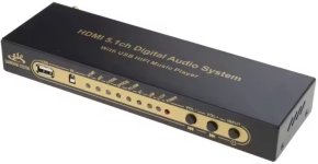
I bought both of these from aliexpress, and I can't get either of them to give 5.1.
I've tried all types of input, and there's either no output to the surrounds, or the surrounds replicate the fronts. The centre has non dialog, and the L/R contain dialog.
Has anyone got these to decode?
I've tried all types of input, and there's either no output to the surrounds, or the surrounds replicate the fronts. The centre has non dialog, and the L/R contain dialog.
Has anyone got these to decode?
Attachments
Hi Guys
- By nadrealista
- Introductions
- 3 Replies
looking to learn and share experiences in everything audio from hifi set ups to speaker mods and amp repair.
my current project is restoring Pioneer Elite TZ-F700 speaker subwoofer amp 🙂
if anyone has experience troubleshooting/repairing these bash boards please reach out.

Login to view embedded media

.jpg")

my current project is restoring Pioneer Elite TZ-F700 speaker subwoofer amp 🙂
if anyone has experience troubleshooting/repairing these bash boards please reach out.
Login to view embedded media
For Sale Hagerman FryKleaner
This is the original audio burn-in generator by Hagerman. I assembled it. It has never been used. $75 plus postage.
Thanks for looking.
M


Thanks for looking.
M
6GM8/ECC86 Tube preamp for 30VDC supply
- By lineup
- Tubes / Valves
- 79 Replies
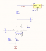
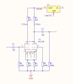
I have decided to build my first TUBE amplifier. Using ECC86 triodes from Telefunken.
It is a preamp with a little voltage gain. I hope getting good tube sound.
There are 3 different ways to go. The first is simply using 1/2 ECC86 per each channel. This only requires one tube for stereo.
The second way is to parallel triodes in one tube. This needs 2 tubes for stereo Gives twice the current and lowers the output impedance.
The third option is to make a differential tube circuit. This also needs 2 tubes for stereo. This option will preserve the correct phase. While option one and two gives inverted output.
I post here 3 images with the 3 choices. Which one should I go for 🙂
Attachments

SL1200 inexpensive high performance external PS
- By profiguy
- Analogue Source
- 4 Replies
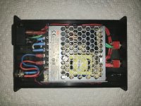
I've managed to put together a low price, high performance power supply for the SL1200 for under $50 parts cost. Its centered around the Mean Well LRS 50-24 SMPS.
This supply is very well built, using United Chemicon capacitors, a well laid out chassis and a high quality PCB design - pretty good for a $14 power supply. Output shows very little noise and ripple with more than enough current (max 2.2 amps) to feed the turntable.
The output voltage is adjustable via a small pot in a very wide range of 20 - 31V. It also has a soft start and a nice status LED. This can be extended out to the chassis for an external power indicator. The SMD series resistor on the bottom of the PCB can be changed to suit the current needed to run other LEDs.
With this PS you can turn the output voltage all the way down to 20V for a direct application, bypassing the stock reg or instead of a 3 pin based circuit. You can also turn it up to supply enough voltage to accommodate the drop of the stock reg or your 3 pin based reg of choice.
The SMPS regulation is very tight and I'd feel very comfortable using this straight into the supply rail of the SL1200's motor PCB. I would however fuse the main B+ rail into the TT if I chose to do this. Its just as a precaution against an eventual fault or failed component inside the TT to protect the main PCB from burning up any traces.
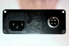
I configure the front panel to include a ground lift switch in case of noise issues due to grounding. Coming out of the PS I chose a typical 4 pin screw lock connector used in many low voltage applications. I left an extra pin available to shield the umbilical cable going into the turntable.
A KAB 3 pin reg board was used inside the TT instead of the stock reg. Honestly, the OE Technics setup is more than adequate for the job as long as the filter caps are all in good shape. Of you need to replace them, I'd recommend the Panasonic EB series caps. They're inexpensive for being rated at 105 deg C along with excellent ripple current capability.
The chassis I used was an enclosure made by Context Engineering, part number 4006. I had it in stock already, as this is an enclosure I use for many projects. I don't know if these are still being made, but I'm sure there still are other suitable enclosures being sold for this purpose.
This supply is very well built, using United Chemicon capacitors, a well laid out chassis and a high quality PCB design - pretty good for a $14 power supply. Output shows very little noise and ripple with more than enough current (max 2.2 amps) to feed the turntable.
The output voltage is adjustable via a small pot in a very wide range of 20 - 31V. It also has a soft start and a nice status LED. This can be extended out to the chassis for an external power indicator. The SMD series resistor on the bottom of the PCB can be changed to suit the current needed to run other LEDs.
With this PS you can turn the output voltage all the way down to 20V for a direct application, bypassing the stock reg or instead of a 3 pin based circuit. You can also turn it up to supply enough voltage to accommodate the drop of the stock reg or your 3 pin based reg of choice.
The SMPS regulation is very tight and I'd feel very comfortable using this straight into the supply rail of the SL1200's motor PCB. I would however fuse the main B+ rail into the TT if I chose to do this. Its just as a precaution against an eventual fault or failed component inside the TT to protect the main PCB from burning up any traces.
I configure the front panel to include a ground lift switch in case of noise issues due to grounding. Coming out of the PS I chose a typical 4 pin screw lock connector used in many low voltage applications. I left an extra pin available to shield the umbilical cable going into the turntable.
A KAB 3 pin reg board was used inside the TT instead of the stock reg. Honestly, the OE Technics setup is more than adequate for the job as long as the filter caps are all in good shape. Of you need to replace them, I'd recommend the Panasonic EB series caps. They're inexpensive for being rated at 105 deg C along with excellent ripple current capability.
The chassis I used was an enclosure made by Context Engineering, part number 4006. I had it in stock already, as this is an enclosure I use for many projects. I don't know if these are still being made, but I'm sure there still are other suitable enclosures being sold for this purpose.
Attachments

Dynaco ST-70 modification help!
- By berlinerpunk
- Tubes / Valves
- 25 Replies
Hello! I have recently purchased an ST-70 from someone who had it for 4 years. He bought it on ebay from a store that got it from the estate of a deceased musician. The late musician either modified it him/herself or had it done by someone else. There is no schematic or record of what was done. All I know is that it comes from around the Woodstock, NY area. I have never seen mods like these before. Bias pots under the chassis (in addition to the regular pots on top!) LED light in the front left octal socket?? Why??? Not sure why they upgraded the quad cap to 80-40-30-20 .... maybe it has to do with all of the extra wiring under the hood. I'm trying to retrace their steps and understand what was done! Hopefully, someone here can help me figure it out. If you need more detailed photos, I'm happy to provide them.
Any thoughts or advice or input you have is welcome!!! I'm a n00b so no advice is too small.
Thx!!!


Any thoughts or advice or input you have is welcome!!! I'm a n00b so no advice is too small.
Thx!!!
Hello there
- By etommmy
- Introductions
- 2 Replies
General small PA, instruments and playing music, maybe HIFI and home AV, but no more audiophiliacs.
Hello everyone!
- By makskr
- Introductions
- 2 Replies
Hello everyone!
I'm thrilled to join this vibrant community of audio enthusiasts. My name is Maxim, I am from Canada, and I'm passionate about all things audio electronics.
From vintage gear to the latest innovations, I love exploring and experimenting with different audio equipment like DJ Mixers, HiFi sources etc..
A bit about my background: I've been involved in the audio industry for several years, working on everything from recording and producing music to designing custom audio systems. I'm particularly fond of vintage audio equipment and enjoy restoring and collecting classic pieces.
I'm looking forward to learning from all of you, sharing my experiences, and contributing to the discussions here. Whether it's troubleshooting a tricky issue, sharing tips and tricks, or just chatting about our favorite gear, I'm excited to be a part of this community.
Feel free to reach out if you have any questions or just want to chat about audio electronics. Let's make some great sound together!
Best regards,
Maxim
DJ-Tech DJM-303
- By makskr
- PA Systems
- 0 Replies
Hi everyone!
Does anyone have experience with the DJ-Tech mixer, specifically the model with plate number DJM-303?
I’m looking for the firmware for the MC9S08AW32CPUE controller.
The chip has completely failed, and I have a new one, but I need to program it first.
Could you please help me locate the firmware file?
Thank you!
Attachments

For Sale Small Solder Pot, bar solder, and small quantities of other solders
- By mattattnet
- Swap Meet
- 1 Replies
SOLD
Asking $60 to include continental USA shipping.
USA sale only.
I have a small Chinese solder pot (36 x 30 mm pot) for sale. Works as it should.
Also included is an additional 1 lb 2 oz of bar solder (Cardas and Wonder Solders)
Additionally, there are some small quantities of other, mainly lead free, solders in the lot.
-WBT-0800 Silver Solder, 2 or 3 oz
-Marigo Labs, 6 ft length. Not sure of makeup.
-Welborne Labs Silver solder, maybe 2 or 3 ounces.
- Fire Metal SN/PB/AG/Cu 1/4 lb.
- Radio Shack 0.5 oz silver solder
No returns. Will need to ship ground due to HAZmat.
Bonjour de Nice France
- By Bithule
- Introductions
- 2 Replies
Bonjour la communauté,
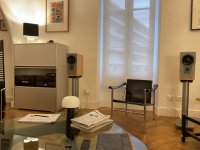
J’adore mon système Thule Audio composé de:
PA + PR 150b CD 150b. TU 150b sur une paire de Dynaudio Contour 1.4S câbles XLR QED
Pour quelle raison avoir choisi ce système? C’est très simple une visite dans un auditorium Parisien un CD de piano à la main suivi d’une écoute de plusieurs solutions jusqu’à ce que le son du piano soit réaliste j’ai dit c’est bon j’avais trouvé chaussure à mes pieds!
J’aimerais partager avec les amoureux de cette marque trop vite disparue et maintenir ces électroniques en bon état de fonctionnement le plus longtemps possible….
Cordiales et musicales salutations🎶🎶🎶
`````
Hello community,
I love my Thule Audio system consisting of:
PA + PR 150b CD 150b. TU 150b on a pair of Dynaudio Contour 1.4S XLR QED cables
Why did you choose this system? It's very simple, a visit to a Parisian auditorium with a piano CD in hand followed by listening to several solutions until the sound of the piano is realistic. I said that's good, I had found a shoe. at my feet!
I would like to share with lovers of this brand that disappeared too quickly and keep these electronics in good working order for as long as possible....
Cordial and musical greetings🎶🎶🎶
Attachments
For Sale Focusrite Scarlett Solo
This was used once for THD measurements before getting a QA403. Original box, paperwork.
Asking $70 which includes shipping to US only, and PP fees.
Thank you.


Asking $70 which includes shipping to US only, and PP fees.
Thank you.
SONY E9000ES
- By kingfisher
- Solid State
- 0 Replies
I pulled this unit from E-waste knowing it will end its life under landfill. Actually thought it was a surround reciever. After further investigation i realized it's a multi channel controller. So, what to do with it? Im a 2 channel person, having any more options is just a waste on me. Is this unit suited as a 2 channel preamp or a better home in stead?
LM3886: Why open input leads to large DC at output?
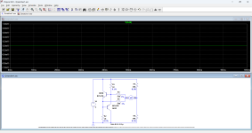
I was experimenting with point-to-point wiring with LM3886. Notice that almost full DC power supply voltage at output terminal! I thought I was losing one side of power supply but after carefully check, the power supply working correctly. Later on, I found that part of the input is not connected, after reconnect it works. I also try shorting the input to ground, there is no DC at output as well.
Why is that? Is it because incorrect input bias when disconnected?? I tried simulate on TINA-TI, and it is kinda show what I experienced.
Closed SW1 = Normal/ correct wiring. Only 1.18mV at output.

Open SW1 = Disconnected input bias circuit. Simulation show 22 V DC at output.

Please share your thoughts.
AP
Why is that? Is it because incorrect input bias when disconnected?? I tried simulate on TINA-TI, and it is kinda show what I experienced.
Closed SW1 = Normal/ correct wiring. Only 1.18mV at output.
Open SW1 = Disconnected input bias circuit. Simulation show 22 V DC at output.
Please share your thoughts.
AP
Topping E30 II Lite on Mac
Hi, is anyone using the Topping E30 II Lite dac on Mac? I have a Mac book pro i7 with OSX 10.13.6 High Sierra and I would like to purchase the Topping E30 II Lite to connect the Mac to my hifi system. Do you know if there is a need to install drives or does the Topping E30 II Lite work without it? Thank you
BJT internal emitter resistance
- By EdGr
- Solid State
- 10 Replies
A recent thread discussed the internal emitter resistance of BJTs and its effects on thermal stability.
Since I was curious, I fitted a BJT model with an emitter resistor to the Vbe-versus-Ic graph in the MJ15003 datasheet. A reasonable match was produced with 40 milliohms at 25C and a 0.16 milliohm/C temperature coefficient. The Vbe sensitivity to temperature was -2.1mV/C and Is was 10^-12 A.


I am curious if anyone has similar data for other power transistors.
Ed
Since I was curious, I fitted a BJT model with an emitter resistor to the Vbe-versus-Ic graph in the MJ15003 datasheet. A reasonable match was produced with 40 milliohms at 25C and a 0.16 milliohm/C temperature coefficient. The Vbe sensitivity to temperature was -2.1mV/C and Is was 10^-12 A.
I am curious if anyone has similar data for other power transistors.
Ed
My second adventure: Simple Integrated
- By spectre6000
- Tubes / Valves
- 22 Replies
A little less than a year ago, I successfully completed my first tube audio project: an RIAA phono amplifier. It was a fantastic success, and my family and I have been thoroughly enjoying it. Winter is coming again here in the Rockies, so it's time to start thinking about indoor projects. At the moment, the preamp feeds into a set of computer speakers, which is pretty anticlimactic. It's time to start working on the rest of system!
I think what I want to do is an integrated amplifier (I might could be convinced to go another route) with a similar basis. I want the most minimalist circuit possible (100% tube and passives), single-ended class A, all analog (including power supply, because this is part of the fun for me), low power (pushing shelf speakers in a living room, rarely might need to compete with a vacuum cleaner), using modern, current production components (future proofing). My current setup consists exclusively of a record player, but there's an ancient Sonos that my wife uses from time to time, and I'd like to replace it with a better streamer down the road (phase three?). A third, maybe fourth channel would probably make for all the extensibility I'd need for quite a while. Aside from that, I think I don't really want much more to it than a volume control, again, for the minimalism to keep the part count to a minimum.
What thoughts or advice do people have for me? Any designs/schematics out there that fit the bill?
UAC2 I2S input on STM32F723E-DISCO
- By bohrok2610
- Equipment & Tools
- 20 Replies
I made a simplified version of my STM32F723 firmware for STM32F723E-DISCO board with just I2S input (no I2S output). Should work at least at 192k/32.
It uses this board:
https://www.mouser.fi/ProductDetail/STMicroelectronics/STM32F723E-DISCO?qs=DXv0QSHKF4wBapbNjrzotQ==
Attached is the source code. It runs on FreeRTOS although this version does not really utilize it.
I used STM32F723E-DISCO board's Arduino connectors CN11 and CN13 for all I/O.
I2S signals are at CN11.1 (FS), CN13.4 (BCK) and CN13.7 (SD).
I2C2 is available at CN11.10 (SCL) and CN11.9 (SDA).
4 GPIO outputs at CN13.3, CN13.5, CN13.6 and CN13.8.
GND at CN11.7.
The source code also includes a "driver" for my AK5394 board which uses all 4 GPIO outputs. This can be used as an example of how to connect to ADC board.
STM32F723E-DISCO board is of course not optimal for running I2S as it is meant to be a showcase of various MCU capabilities. For best results a custom board dedicated to I2S should be used.
Have fun!
Attachments
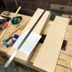
Castle microtower build with EL70
- By trumper
- Full Range
- 28 Replies
Well after much procrastination (and waiting for nicer weather....) the build has begun.
Attachments
Matching complimentary BJT pairs
- By spuddo
- Introductions
- 4 Replies
Hi first time poster.
I am restoring a '73 Minimoog synthesizer and it requires a complimentary pair (in this case 2N3904/2N3906).
I noticed in a previous post that a test circuit designed by Elvee might be the answer.

The attached is the circuit from the Minimoog service manual.
In note (4) the request is that the PNP Vbe is 10-20mV lower than the NPN at 200mA.
I'm not an engineer, but I think at that current it would deep fry the BJT's or cause thermal problems in the matching process.
Any help appreciated.

I am restoring a '73 Minimoog synthesizer and it requires a complimentary pair (in this case 2N3904/2N3906).
I noticed in a previous post that a test circuit designed by Elvee might be the answer.
The attached is the circuit from the Minimoog service manual.
In note (4) the request is that the PNP Vbe is 10-20mV lower than the NPN at 200mA.
I'm not an engineer, but I think at that current it would deep fry the BJT's or cause thermal problems in the matching process.
Any help appreciated.
Xonar ST/STX mods...
It is a quite long time now I`ve started to mod my Xonar STX. Now is finish this work. The result: you will not believe it (DIY...)
For those interest in this task, I open this thread...
Some pictures to follow...
For those interest in this task, I open this thread...
Some pictures to follow...
Mic / SPL calibrator - cheap ones on Amazon (or elsewhere?)
- By AdamThorne
- Equipment & Tools
- 19 Replies
Anyone using a mic calibrator?
Not frequency response, just level - 94 / 114 dB @ 1 kHz. I do acoustic measurements, the mic has a cal file but the sound card I have has a gain knob. So FR should be right(ish) but who knows about overall sensitivity. So, calibrated reference source to the rescue.
B&K and GRAS make expensive ones and that's great when work is paying. But for hobby projects I'm looking for something cheaper. There are a few of them for sale on Amazon for around $100. Are any of them worth while?
Let's see, here are some examples...
Reed Instruments R8090 - $179 (the expensive one!)
This silver cylinder calibrator - sold by multiple vendors - ~$111
Grey rectangle with orange band calibrator - multiple vendors - $79
Black cyl with blue LCD - $109 (sometimes this one is called ND9B, but then it's ~$200)
Anyone know?
A bummer - these all seem to be targeted at SPL meters and accomodate 1" and 1/2" mics but I think the typical FR measurement mic is smaller. I can probably 3D print an adapter, if I seal it...?
Allison Six _ what is your opinion?
- By ginetto61
- Everything Else
- 16 Replies
Hi ! i am watching this most unique speaker The old Allison Six

i do not understand the rationale behind this design
I guess that the cross Hz between the woofer and the tweeter should be around 2kHz ?
for a good part of its range the woofer should be directional
I wonder what the designer tried to achieve
Can anyone explain me please this design ?
I would like to replicate it but with a wideband in place of the tweeter and lowering the cross frequency
What would be the best cut ? 500Hz ? less ?
i am lost but intrigued
Prehistoric Resistors
Draloric Polywatt Resistors with screw terminals:


I found them in an abandoned Lab in the University-Hospital where I work.
Never seen resistors like that before… the one in the housing is a potentiometer.
I found them in an abandoned Lab in the University-Hospital where I work.
Never seen resistors like that before… the one in the housing is a potentiometer.
What chip is in HW-715 AliExpress module?
- By addysoftware
- Class D
- 2 Replies
Hi all,
I bought a small cheap amplifier from Ali, claimed to be TPA3116 (but cannot be, of course, at this price; i just hoped will be some 10W peak but is not, at least not on 4 ohms), and I did some tests. Audio speaking, appears to cough (typically overload audio interruptions) at beyond 3W peak/6 ohms (subjective, hearing only) . Current supply from 12 to 24V rises a bit from 25 to 30mA (for the whole board) . Oscilloscope output shows that the rectangles are full voltage, so is not supplied through some kind of internal buck converter. The output frequency is at 370kHz.
Peaks seen on oscilloscope appears to be at 700mA at 8 ohms and 1A at 8 ohms, irrespective of voltage (12-24V) but dynamic response is far better at 24V, audio interruptios are rarer.
Do anyone knows what chip was really used in these?
Transistor matching circuit
- By JonesyF
- Electronic Design
- 5 Replies
Hi guys,
I'm trying to build a circuit to match NPN and PNP transistor pairs for my SymAsym amplifier. The basis for this exercise is the paper by Ian Fritz, see https://www.dragonflyalley.com/synth/images/TransistorMatching/ianFritz-transmat0011_144.pdf
Since I need +12V and -12V I want to use my lab power supply at 24V and use a virtual GND with voltage divider.
Here is for example the circuit for PNP matching made with LTSpice:

Voltage across the leads on the right side is measured for calculating the mismatch. R4 and R5 values should be as close as possible. I want to use 1% tolerance resistors, that's why I simulate with 99k and 101k.
The NPN version looks like this:

Due to the simple voltage divider the voltages are not +12/-12V but +13.18/-10.82 V for the PNP version and +10.82/-13.18 V for the NPN version.
I don't see a problem with that, except for the difference in current at which the transistor mismatch is measured.
Will this work? Am I missing something?
Best regards,
Jonas
I'm trying to build a circuit to match NPN and PNP transistor pairs for my SymAsym amplifier. The basis for this exercise is the paper by Ian Fritz, see https://www.dragonflyalley.com/synth/images/TransistorMatching/ianFritz-transmat0011_144.pdf
Since I need +12V and -12V I want to use my lab power supply at 24V and use a virtual GND with voltage divider.
Here is for example the circuit for PNP matching made with LTSpice:
Voltage across the leads on the right side is measured for calculating the mismatch. R4 and R5 values should be as close as possible. I want to use 1% tolerance resistors, that's why I simulate with 99k and 101k.
The NPN version looks like this:
Due to the simple voltage divider the voltages are not +12/-12V but +13.18/-10.82 V for the PNP version and +10.82/-13.18 V for the NPN version.
I don't see a problem with that, except for the difference in current at which the transistor mismatch is measured.
Will this work? Am I missing something?
Best regards,
Jonas
Low cost and low noise regulator?
- By Ghoostknight
- Power Supplies
- 24 Replies
what do you guys think is the best regulator in terms of price/performance?
LT3042/LT3045 still seems to be the best performing for around 5/10 euro, tho im wondering if some good regulators exist that cost half as much ?
TPS7A700 is a bit cheaper
LT3042/LT3045 still seems to be the best performing for around 5/10 euro, tho im wondering if some good regulators exist that cost half as much ?
TPS7A700 is a bit cheaper
-
Locked
Building the Lhotse designed by Scottmoose
- By Hondasnl
- Full Range
- 84 Replies
I have a matched pair of the MAOP 11 and want to built the Lhotse with them.
I already started fabricating them, nice speaker!
I already started fabricating them, nice speaker!
Attachments
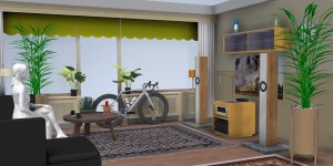

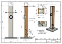
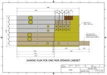
Oppo BDT-101CI "Unlock your OPPO Blu-ray......"
- By mprivitera1
- Digital Source
- 3 Replies
Hi guys,
I have an Oppo BDT-101CI, I would like to unlock the region for DVDs, I found this online
https://www.oppodigital.com.au/pages/superdisc-unlock-your-oppo-bluray-player-for-all-dvd-regions
Do you think it is compatible with my Oppo?
The site is Australian..!!
Thank you
I have an Oppo BDT-101CI, I would like to unlock the region for DVDs, I found this online
https://www.oppodigital.com.au/pages/superdisc-unlock-your-oppo-bluray-player-for-all-dvd-regions
Do you think it is compatible with my Oppo?
The site is Australian..!!
Thank you
Bag End 400 A Infra 18 Sub Amp
- By cvrc
- Introductions
- 1 Replies
Hi I am Christos Spanoudes , 71 YOLD , electronics engineer, building DIY since i was able to solder, designed / built / serviced mainly PSU and audio gear but also control circuits , 40 years under name of CVRC ELECTRONICS , retired , now electronics is just for fun and hobby.
my question following a relative thread on this forum :
I have an amp that output devices Originally were 2SA1302 / 2SC3281 ( BAG END 400A )
Found a good direct replacement for the output devices possibly to be MJL1302/MLJ3281
The output driver transistors were 2SC3907 and 2SA1516, and i found equivalent to be possibly 2SA1943/2SC5200,
but could one use the MJL1302/MLJ3281 ( TO264 ) or even the smaller case NJW3281/NLW1302 ( for same case ) ,
as drivers to the MJL1302/MLJ3281 ?
because the MJL1302/MLJ3281 and 2SA1943/2SC5200 have spec almost same between them , except for case and max power etc.
and the MJL1302/MLJ3281 will be more robust if they will work ok .Unless there would be a catch .
Any response welcome to start in this super nice / useful ( I found ) forum.
Detecting crossover part from board
Hi guys i have a Panasonic ch9 . Bookshelfs are ok but amplifier is dead . It have onboard crossover . Its a pre amp if i say it right . I want to detach crossover from board and attach it directly to speakers . Can you help me about it please

New Issue Scrolling broken on iOS & Firefox
- By sheeple
- Forum Problems & Feedback
- 3 Replies
hi, I am experiencing problems since a couple of weeks with scrolling in mobile view on a fully updated iOS device (18.2.1) with up to date firefox as browser (Firefox 134.1 (49636)). This started a while ago, maybe a month. I have no addons installed.
description: the scrolling does stop, and does not float. it happens either way no matter whether the finger is released from the screen, or touching will scrolling. this behavior is periodically interrupted by a normal scrolling experience.
description: the scrolling does stop, and does not float. it happens either way no matter whether the finger is released from the screen, or touching will scrolling. this behavior is periodically interrupted by a normal scrolling experience.
New Balance Potentiometer for Rotel RA930AX
- By lqw97
- Solid State
- 3 Replies
Hi All,
I am looking to replace the balance potentiometer for the rotel ra-930 ax. Trying to work out which replacement will be most suited. I think the resistance value is 100k ohms. I'm currently looking at some options by Bourns, but it's hard to know which is the right one. Any thoughts/links to appropriate replacements would be welcome, thanks!
I am looking to replace the balance potentiometer for the rotel ra-930 ax. Trying to work out which replacement will be most suited. I think the resistance value is 100k ohms. I'm currently looking at some options by Bourns, but it's hard to know which is the right one. Any thoughts/links to appropriate replacements would be welcome, thanks!
Finished Aleph J build - first thoughts and comparison to my other gear.
- By canonken
- Everything Else
- 5 Replies
I thought this would fit best here, as it is more of a 'whatever we want to talk about' post vs. putting it in the build thread or the like.
First, I won a gold medal for the s l o w e s t build, I think ordered the parts 4 years ago, and due to a job change, move, life stuff, I got the power supply built/tested, then didn't progress from there. Anyway, finally got it done and running today. Everything went smooth, no issues at all (I was VERY careful and sweated the details).
My main system is a McIntosh C53 preamp and I have a MC462 (450 watt SS amp) and MC275 (75 watt tube)...I swap between the amps as I feel like. like them both for different reasons. I also have the little 2.3 watt Decware Zen amp (it has some background hum that is preventing me from falling in love with it). I'm currently using and loving a pair of Zu Audio DW6 I picked up at the factory (about 45 minutes away, my welcome to Utah gift). Also have a pair of Sonus Faber towers that are currently off to the side while I enjoy the Zu's.
The main reason I did this build was to learn and sharpen my skills. I learned a TON, not only about electronics, but the build process. I remember the first time I tried soldering vs. now, where I can 'feel' the molten metal flowing and manipulate it (but still a lifetime of learning, I'm no pro!). As such, the amp itself was more of a curiosity and side effect vs. the main attraction. Maybe it would be good, maybe not, but not really the point.
***
Holy ****... I've been listening to it all evening, and I'm still not comprehending it. OK, maybe I am just in a really good mood tonight - but need to say my personality is NOT one of a honeymoon, most things I buy (or make) I generally don't like at first, then either stay that way...or grow to like them. This amp just immediately grabbed me and had be stand to attention.
OK, as I was listening, I was trying think of ways to describe what I was hearing. Like riding a motorcycle for the first time after driving your whole life, yup. Like standing at the rim of the Grand Canyon in person after seeing a documentary on it, yup. Like listening to a set of good headphones (I really got that feeling), yup. Like playing a synthesizer vs. hearing a recording of one, yup.
The sound clear, immediate, fast, nimble, precise, liquid. It is almost like the sound is playing faster than my brain can keep up with. And on these high-sensitivity speakers, ENDLESS power and dynamics. The speakers felt like they were pulled up close to me, the imaging was wider, taller, deeper. Also on a technical note, zero background hum or hiss (something I can't say for the Decware).
I'll make a quick reality check to say I HATE bright sound - and while this amp certainly brings endless high frequency energy, not once was I wincing or wanting to turn it down for being bright or shrill. This also means a product that tries to sound 'lively' by being bright is immediately on my naughty list. I think this amp would be a disaster with a bad source, the wrong speakers.
While I still like my other big amps, this one is special, and I have a LOT more listening to do.
I was not expecting this outcome, and that is not a bad thing!
hello!
- By ducksoup18
- Introductions
- 1 Replies
Longtime lurker here but i finally got to a point where im stumped and am hoping that one of you geniuses are able to help me out. I run roughly 12 picoreplayers pumping to 3 12 channel amps for whole home audio. Prior to that i used Amazon Echo Flexes since they had a headphone jack out and that worked well. Since moving to picoreplayers (using squeeze and airplay paired with LMS or music assistant) i've run into some unique use cases that the echo's handled fine.
Basically im looking to learn more about if picoreplayer can detect different audio input from different sources (airplay from my phone, squeezelite from LMS/MASS, announcements from homeassistant, etc) and automatically switch audio renderers when a new one makes a request. The issue i have is that if i start airplay from my phone and then there is an announcement or something from home assistant (via a direct squeezelite integration or via MASS) it just turns airplay off but doesnt play the announcement.
Im hoping to find a solution that can be a controller and switch between different audio sources on the fly. I have messed with volumio and moode in the past as well. Moode was close. it actively stops the audio renderer but there were some issues with it relying on MPD as the main audio renderer vs squeeze or airplay. I am familiar with the Wiim devices and they seem to be able to do this but i am already invested with these pi's and would love to find a solution to this. TIA!
Sonos Port S2 Model S23 output audio not working
- By 3lp4tr0n
- Introductions
- 1 Replies
hello i have a Sonos s2 port model s23 that output audio not working was working for a year no issues but now nothing works it plays in the app also when i connect my laptop with music it wont work either ...i opened the box looked at the boards capacitors and i don't see any that look exploded looking at the RCA Qr code give me this 54303rc1mvd47c1a and the main board QR code give me 62202mb1mu7be71a.. i hopping that i could find out whats the issue im ordering a meter to test caps...if any body had this issue please let me know... thank you
Hello
- By Scott T
- Introductions
- 1 Replies
By way of introduction, I have but a single question that involves a stereo board amp I want to use in bridge mode (BTL). The board/chip is a TDA7498 and info on which jumpers config for bridge mode and which output to use is very scarce. I will start a new thread elsewhere when I can, if necessary. Thanks.
Scott T.
Scott T.
Attachments
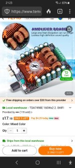
Howdy
- By Alhoare
- Introductions
- 1 Replies
New poster looking at restoring my old hifi gear and some recent 2nd hand additions to the collection.
Load more
Projects by fanatics, for fanatics
Get answers and advice for everyone wanting to learn the art of audio.
Join the Community
508,483
Members
7,921,513
Messages