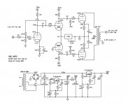
"Iron Concertina" MosFET amp

Hi,

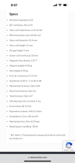
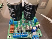
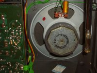
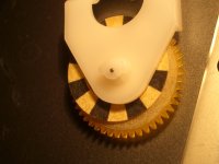
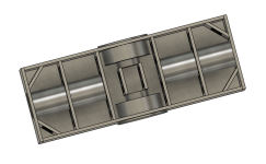
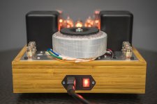
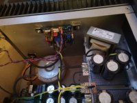
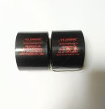
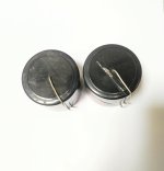
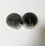
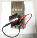
I was digging through some junk the other day and found a pair of interesting chokes that I bought some time ago and then more or less forgot about. Signal Transformer CL-2-4, a rather small piece of airgapped iron with two 10mH windings that can be wired in parallel for 10mH 4A or in series for 40mH 2A.
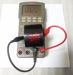
40mH 2A sounded close enough to the specs of the Triad choke used in the Zenductor amp and those dual windings struck me as interesting.

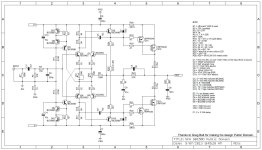
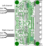
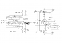
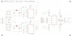
Over at the tube forum, we would call this a "Parafeed output stage with 50% cathode feedback" or perhaps "a single ended version of the Macintosh Unity Gain output stage" or maybe even "What the hell is that, and why doesn't it glow?":
ironconcschema.jpg

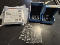
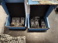
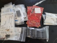
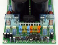
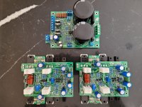
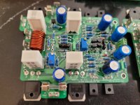
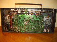
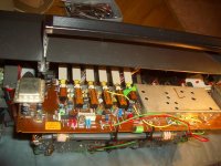
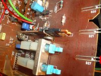
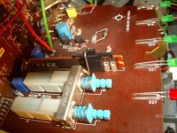
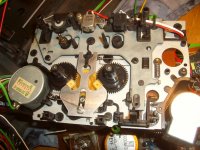
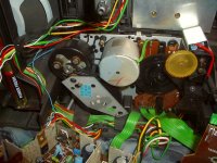
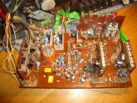
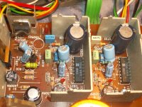
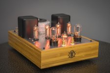
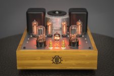
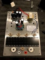
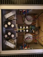
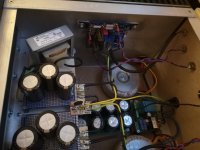
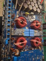
Fortunately, I had a pair of old 2SK133 mosfets with bias circuits and everything already attached to heatsinks after my attempts to duplicate Hiragas Nemesis amp a couple of years ago so wiring up a prototype was easy:

ironconcertinaplaying.jpg

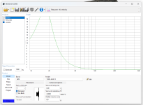
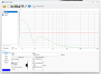
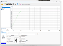
No measurements yet but I've been listening for an hour and it sounds surprisingly good, running at 12V 900mA, which should be good for around 3 watts into 8 ohms.
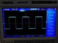
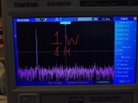
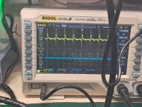
The point here was to build something that is essentially a simple follower but with ~6dBs of gain. The experiment is successful so far, we'll see what the oscilloscope says...
  • Like
Reactions: Nelson Pass

For Sale Hi End Audiophile JH Synchronous Turntable with Formula 4 Arm

JH Reproducers Synchronous Turntable with Formula 4 Arm; Australia’s Linn Sondek. Uprated model with springs.

Excellent reviews, especially the Uni-pivot arm. Motor runs, plater runs, belt OK missing a screw for the cartridge, anti-skating bucket is there just needing attachment.

Photos from part of the description. No warranties, no guarantees, no returns.

I am no expert. What you see is what you get.

Dirt cheap at AUD465, plus shipping/insurance/box. Bank Deposit or PayPal Family & Friend for Overseas people.

Negotiable. But if not sold by 16th December, it goes to the charity shop with the other things.

Attachments

  • 20240908_173245.jpg
    20240908_173245.jpg
    392.9 KB · Views: 92
  • 20240908_173252.jpg
    20240908_173252.jpg
    358.6 KB · Views: 97
  • 20240908_173302.jpg
    20240908_173302.jpg
    532.2 KB · Views: 89
  • 20240908_173309.jpg
    20240908_173309.jpg
    303.1 KB · Views: 93

NAD 356 short/someone help follow the short trace?

After a bit of work by some tuning with Nichicon UKW Caps and a great new Bourns Trimpod (that makes the Power-drive sense. adjust. now and fixed a diode problem in the Amp everything worked fine and i was pretty happy and couldnt wait to listen...
20241108_193135.jpg

Till...
...I wanted to dial in the idlecurrent before and by that I shorted the Amp at the TP Points.

I kind of feel I damaged the Amp seriousely and would appreciate if its possible to help me out a bit to determin which parts got probably damaged by the cuircuit I've created, by showing you what happens, because my shematic reading abilitys are kind of limited.

I marked the short with the black line in the following pictures [the DMM clamps, I surely think touched TP2 and than the 0.1 Cap in front of it - TP1, was not hooked up at that point]

20241108_194711.jpg

Screenshot_20241108_211131_Drive.jpg

Screenshot_20241108_211229_Drive.jpg

So as the short happened the blew was pretty heavy and I shut down the Amp immediately. After turning it on again, I saw smoke coming from R243[marked it with the red cross(the resistor is surely burned)] and then instantly the main Fuse at the PS burned trough also.

So by looking at the Images can someone determine what will be surely damaged especially? (maybe the following Transistors? Output Transistors?)

So I have the 0.1uf cap and the resistor here and about to change them, but im too afraid and don't have the courage to try turn it on yet as I don't know if following parts in thr cuircuit are pretty surely dead.

Thanks!

DUNE HD MAX - REPLACE INTERNAL BLURAY PLAYER....HELP!

Hi guys,

I have this media player, unfortunately the bluray player doesn't work properly, once you insert the disc into it, it says "no disc to read".
I would like to replace its internal reader, but there are no specifications on it online.
What advice is there on a compatible player?
Thank you

Attachments

  • 1733344896784.jpg
    1733344896784.jpg
    622.8 KB · Views: 61
  • 1733344896775.jpg
    1733344896775.jpg
    399.2 KB · Views: 58
  • 1733344896769.jpg
    1733344896769.jpg
    247.8 KB · Views: 50
  • 1733344896775.jpg
    1733344896775.jpg
    399.2 KB · Views: 59

HSPY 400-01 strikes - how to repair it?

Hi all

Well ok this thread is not about a tube amp, but I guess it might be the right place to get in contact with other HSPY 400-01 users, as it is very useful for diy tube amp creators. With its 400V 1A and approximately 250$, it suits perfect for tube lab projects!
One of mine did so for close to 3 years, but the last time, it took several attempts to release output. And since some days, it strikes totally. When turned on and released, in changes immediately into "CC" current limit mode, but no voltage at all is provided.

Does anybody experienced similar behavior?
Is there any chance to repair it?
Does somebody own a schematic?

Thanks for all hints!

BR Adrian

Attachments

  • HSPY _400-01.png
    HSPY _400-01.png
    291 KB · Views: 156

Vintage Belles 400 - any info?

I know, I know, call Dave. Well I emailed him and haven't heard anything back. I was just wondering if anyone here at DIY had any information on this classic gem of an amp?

I just bought it on Ebay and assume it is 200wpc, but have no other information on how its built and the specs associated with it. It has replaced my Yamaha M85 as the amp for my mains. The Yammie is 265Wpc with Class A to 30W.

The Belles doesn't quite have the same punch, but it is smoother with better soundstage imaging and instrumental separation. I couldn't be happier with the sound, now if I could just get a few details on this thing.

Anyone? 😕

Attachments

  • pic%20062w.jpg
    pic%20062w.jpg
    118.1 KB · Views: 352
  • pic%20065w.jpg
    pic%20065w.jpg
    157.8 KB · Views: 312

Help with Amp Pot bypass modification

I got this Fosi 2.1 amp because of the controls it has, and the power output specs are likely good for the cost, even if it only outputs 25% of the advertised specs RMS. https://www.parts-express.com/Fosi-...mplifier-165W-x-2-350W-x-1-235-258?quantity=1

Unlike a similar $30-40 2.1 caseless amp that has independent volume controls for treble and subwoofer, and no bass adjust for the treble, but it does have a master volume knob, the Fosi has the treble bass, but no treble volume. The problem is that I can't turn down the treble independently of the sub without turning the sub down.

Any ideas about how to safely go about finding out how to send signal past the master volume to the sub volume knob? Maybe probing around with a resistor? Any idea of where to start other than likely between the master and sub volume?

Left to right: Sub Freq, Sub Vol, Treble, Bass, Master Volume.
DSC03251 (1700x677).jpg


DSC03252 (1500x991).jpg


I'm not sure what this little switch is for, it was up against a little patch of clean aluminum on the otherwise entirely black front plate. Maybe an anti tamper self destruct switch?
DSC03249 (1195x1280).jpg

SB Acoustics 4” Inch ceramic driver questions and advice?

Good morning Everyone😊. So am looking at building a small book shelf speaker for Tv and background music duties. I know SB Acoustics is A great company to buy from. I like this driver because with different Temperatures in Michigan it will not effort the sound of a these drivers (like paper which is one of my favorites). So is this driver worth$75.00 each At Madisound? The driver is the SB 12CACS25-8 is the model number of the speaker driver am looking at and I included the picture and specs and Frequency graph. Am again not looking to shake the pain off my walls or try and blow my out of my room. Does anyone know the sound of these drivers? I know each company has a signature sound to their driver brand. Am looking doing a passive crossover 12 DB on the tweeter and 6 DB on the woofer. Am looking at building a rear ported box or port slot? I Do Have a Vifa Ring tweeter but, am looking at an Morel tweeter for their flat frequency response and a smooth sound. Please let me know your thoughts? Any advice would be greatly appreciated. Towards this new project am starting. 😊. Be blessed. Jeff

Attachments

  • IMG_5109.png
    IMG_5109.png
    579.8 KB · Views: 149
  • IMG_5111.png
    IMG_5111.png
    237.3 KB · Views: 127
  • IMG_5110.png
    IMG_5110.png
    532.3 KB · Views: 133

Converting my Car Subwoofer setup for home theater use - settings questions…

Before you are 2x 12”, 4Ω, dual voice coil subwoofers that are individually wired for 8Ω each and then wired in parallel to a Class D mono block amp for a total resistance of 4Ω. The amp is powered by a power supply that’s rated at 12V 125A 1500W DC.

The subs are these: Rockford Fosgate P2D4-12

This will be going into a closet behind my A/V wall.

This will be used in my home theater using a Marantz NR1403 as my receiver (NR1403 - AV Receivers)

My main speakers are these: CBM-170SE BOOKSHELF MONITOR PAIR


Here are a few more pics of the subwoofer itself: Login to view embedded media
What would be a good baseline to start at? I am not looking for over the top volume and crazy attack like I used to when this was in my trunk.

you can see the amp adjustments in the pic

I would like something more subtle that focuses mostly on super deep frequencies for the movie action.

Of course there will be some Jazz and Death Metal happening as well.

Thanks for reading!!

IMG_4480.jpeg
IMG_4333.jpeg

Anyone used Nichicon LGX Series?

While finalizing the recap of my Accuphase C200 pre amp I’m looking at purchasing the last bits and bobs, which are the main PSU capacitors. For one position I’m looking at Nichicon LGX. They are fairly long life and have high temperature capabilities. They don’t state any ESR values in the spec sheet tho. Anyone here that have any experience with them that can chime in? In Nichicons own words they’re supposedly ”Ideal for rectifier circuits of general inverters and switching power supplies”. Here’s the data sheet for anyone interested: https://www.mouser.se/datasheet/2/293/e_lgx-3082384.pdf

Fork terminals for speaker wires

I'm entering the final stages of my floorstanding 3-way tower build and I'm starting to thinking about making a nicer set of speaker wires to hook them up with. By "nicer" I simply mean terminating the bare wire ends to that I'm not clamping down on bare stranded wires which will eventually break off.

My cabinets will have these Dayton Audio binding posts which accept banana plugs or large fork terminals.

I'm hoping to find some solder-on banana plugs or appropriately sized fork terminals to make a nice tidy termination, however everything that I'm finding on Parts Express are set-screw style.

Does anyone have any leads on where I might look to source some nice solder-on terminals? I'm a bit particular with having my wiring look neat, similar to these:SVS SoundPath Ultra Speaker Cable

ZVN3306/ZVP4424 mosfets for FC CEN IV through hole

Dear all,

This is a group buy for ZVN3306/ZVP4424 matched sets for the FC CEN TH group buy.

Priority first for European based 1st GB participants. All Euro based GB1 participants - If I do not hear from you by Friday 25th November (next Friday) then I move on to GB2 participants - I expect I will be near shipping of the GB2 boards at that stage and it is only reasonable to send out the mosfets with those at that time.

GB1 European participants are:

G600
ernesternest
Jogi
bogdandascalu87
Awh
Vavilen
jimk04
1543
neils73
galac
BDL
StevenCrook
topicreader
Yosyos
wealas
Oyvind

How much do they cost?

A set of matched mosfets for 1 stereo pair of FC CEN IV will be 12e. The killer here is shipping - the cheapest tracked shipping I can find is €9 - having said that, every single pack was delivered quickly and securely during the group buy. So the total price for a stereo set is €21.

Add your name below here and indicate how many sets you need (ie 1 set = 1 stereo pair, 2 sets = 2 stereo pairs or 1 balanced pair). Shipping is the same whether you are buying one or two sets.


Folks - with these two group buys we are straddling two different sets of people, with separate billing and shipping. It will take a little extra organisation and I ask for your patience as I get it together.

Fran

For Sale USSA5, pcb Rev 0.4.5 with Parts, and Mosfet

FS: Complete Parts kit for the USSA5 amp, including the output Mosfet, difficult to source K2013/J313, JFET and matched hfe input pairs.

Asking 250U$ + Shipping + 3.5% Paypal fee (or use Friends or Family)

Kit also includes detailed assembly instructions from Fab the designer.
The circuit needs adjustment on some parts in-circuit (CCS current, Vgs, etc). It is well explained in the assembly procedure.

Thanks
SB

Attachments

  • 20241201_110147.jpg
    20241201_110147.jpg
    443.3 KB · Views: 126
  • 20241201_110154.jpg
    20241201_110154.jpg
    313.6 KB · Views: 121
  • 20241201_110224.jpg
    20241201_110224.jpg
    509.9 KB · Views: 122
  • Like
Reactions: birdbox and Nikos

For Sale SKA150 Amp kit, GB150D2 PCB (& most Parts)

For Sale, SKA150 amplifier PCB kit, with GB150D2 PCB, with matched input transistors, directly from SKA, incl. most of the parts to complete the amp PCB, such as the Bourns trimmer, caps and some high end parts such as Takman & PRP resistors.

All the remaining parts are easily available. To complete the PCB you'll need the final MOSFET, the usual IRPF240, IRFP9240, some MFR25 Metal film resistors and a few other bits.

These PCB came with a detailled assembly guide, and I'll include all my own detailled docs, such as my own detailled BOM, PCB silkscreen, schematics, etc.

This amp was well reviewed, is easy to build. A steal at this price, paid 108$ for the two pcb and matched transistors only. Too many projects already, this one need to go.
The assembled PCB picture is included only as a reference.

Asking 100U$ + shipping + 3.5% Paypal fee

Thanks for looking
SB

Attachments

  • GPA150 Amp kit.jpg
    GPA150 Amp kit.jpg
    514.1 KB · Views: 272
  • Schematic.JPG
    Schematic.JPG
    168.2 KB · Views: 247
  • Silkscreen.JPG
    Silkscreen.JPG
    57.8 KB · Views: 265
  • Left_top.jpg
    Left_top.jpg
    45.4 KB · Views: 247

For Sale PA03 LM4780 Chip Amp PCB kit and all parts

LOWER PRICE: PA03 60W Chip Amplifier, from Sjostrom Audio, LM4780 Chip Amp PCB kit and all parts (incl. the LM4780 chips)

The kit inludes a pair of very high quality amp pcb, the now obsolete LM4780 amp chips and all the parts to complete the amp (excluding the heatsink). All parts are original bought from Mouser and Digikey at the time. The amp has the option of Single-ended or balanced input. It also includes the speaker protection circuit and relay. The assembled pictured are for reference only. Full schematic and BOM included with the sale. You need an external power supply (transfo, rectifier, caps) to complete the amp...

I have an Antek 300VA, 16V (Part No. AN-3216) in stock that can sell for this amp at a good price, if interested. Shipping cost would be higher though...

Asking NEW LOWER PRICE of 200U$ o.b.o + shipping + 3.5% Paypal fee

Thanks for looking
SB

Attachments

  • 20230313_135043.jpg
    20230313_135043.jpg
    504.8 KB · Views: 283
  • pa03_detail.jpg
    pa03_detail.jpg
    74.2 KB · Views: 271
  • pa03_detail_2.jpg
    pa03_detail_2.jpg
    95.5 KB · Views: 275
  • pa03_input_balanced.png
    pa03_input_balanced.png
    38.5 KB · Views: 252

For Sale Hifisonix NX-Amplifier: A High Performance 100 W class AB Current Feedback Amp, assembled kit

NEW LOWER PRICE For sale a fully assembled pcb kit for the Hifisonix nx-Amplifier: A High Performance 100 W class AB Current Feedback Amplifier. Hifisonix still sell the bar pcb kit, and support it.
The kit contains 2 amp PCB and the PSU with speaker protection. The PSU PCB already contains the rectifier and filtering caps.

To complete the amp you only need the usual power transformer, and chassis.

I have the full documentation, detailled BOM. See hifisonix website for details at https://hifisonix.com/projects/nx-amp-audio-amplifier/

All the pcb are professionnally assembled, with high quality parts. Selling for the price of parts.

Great kit, but need to reduce my projects. sorry to let this one go. Your chance for a great kit...

Asking 250U$ o.b.o + shipping + 3.5% Paypal fee

Thanks for looking
SB

Attachments

  • 20230315_152601.jpg
    20230315_152601.jpg
    262.4 KB · Views: 452
  • 20230315_152607.jpg
    20230315_152607.jpg
    193.7 KB · Views: 455
  • 20230315_152628.jpg
    20230315_152628.jpg
    198.7 KB · Views: 404
  • 20230315_152711.jpg
    20230315_152711.jpg
    196.5 KB · Views: 434

RH84 with Type 80 build and review

For a number of years I've wanted to build a single-ended EL84. This particular design has been been built many, many times successfully: it's simple, inexpensive to build and has an interesting plate-to-plate fb scheme.(This design and it's designer have generated a fair amount of discussion over the years. I don't want to get into any of that in this thread)

There are two official versions of this amp: I built the newer, second version which employs an LM317 cathode bias scheme and the grid resistor being replaced by 21v zener. I do plan on swapping the zener with 3w power R to hear the difference.

There are a couple of BOMs posted online, so you can do a quick Google search to find those. Just beware that one BOM will be version 1 and another for version 2.

I chose the direct heated Type 80 (5y3 equivalent in a UX4 pin base) for several reasons: I buddy gave me some (Thanks Dr. Steve Curry!) and they have a high anode impedance, which may lead to a quieter supply, hence a better sounding supply. Also, I think the ST bottle is really cool looking and it's 1920's technology, with the design really beginning in late '23 and finalized as the 280 in 1927.

There's a lot of disagreement on the forums regarding types of supply and components. I won't get into that here, but the supply with the Type 80 rectifier turned out to be incredibly quite. Therefore, a quieter supply would absolutely contribute to a better sounding amplifier.

The are two downsides of the Type 80: it dissipates a very large amount of energy, making it incredibly inefficient. Therefore, you need to consider the heat output in your layout or how that will work in your environment. Living in Arizona this is a factor. I do run a very quiet ceiling fan in my audio room that helps tremendously during summer months, however, this will end up being a winter amplifier. I needed to use PSUD and get some advice on Vdrop: The Type 80 has a very high voltage drop (at least 60vdc), hence lower power output. I chose an over-sized Hammond 273BX, which has 700Vac center-tapped secondaries. I think that 650Vac center-tapped would have been just adequate. I did have to reduce my B+ some 45 volts. In any case, the RH84 circuit presents approx. 100mAh load, therefore, there was plenty of current delivery for the audio circuit!

During this time period, I read Morgan Jone's book and I highly recommend it, it's a fabulous read. I've built a lot of SS amps, but this was my first tube amp from scratch. So, I needed some help!

The top plate was just scrap metal, holes were perfectly opened with a cheap stepped bit that I've used for lots of projects. The bottom of the plate was cera-coated to prevent unwanted grounding (not really necessary but buddy offered). The top was sprayed with my time honored method of finishing metal: self-etching primer shot from a rattle can, sanded, shot again, to fill scratches in imperfections in the metal. Then rattle canned with Rustoleum Hammered finish. This stuff is awesome, and even in sunlight you see no imperfections. My 3rd coat is always a heavy wet coat that floats the hammered flake really nicely. I always allow this paint to dry for at least a week. The drying time is critical an it's also critical that you shoot quick enough to burn subsequent coats into one another. Otherwise, I wait at least 48 hours to shoot another coat. Otherwise, even after 100,000 years, underlying coats will still be wet!

861252d1594952547-rh84-type-80-build-review-img_0133-jpg


Here's the the beginning of the audio circuit with heavy ground bus bar:
861253d1594934659-rh84-type-80-build-review-ground-jpg


Next was to carefully layout the heater wiring, with at least six turns per inch.:
861254d1594934672-rh84-type-80-build-review-complete-circuit-jpg


The base was made from Black Walnut sourced very inexpensively from Ebay. I chamfered the edges to protect against shop "rash" and used my standard and anyone-can-apply-it General Finishes wipe on poly. You simply wipe the product onto the prepared surface, and wipe off the excess, doing so several times creates a beautiful wax finish, with lots of grain pop and depth and no glossy hardness!

The base housed both the very large choke for the Pi filter and Edcor 10w, 5k, 4ohm OPTs. This product is a bargain, and I would argue is as good as exotic output transformers for one main reason: very low primary inductance. Please read this article:

A Consequence of The Quest for 20Hz Roll Off | Cascade Tubes

The completed amplifier:
861256d1594934692-rh84-type-80-build-review-front-jpg

861257d1594934699-rh84-type-80-build-review-jpg


The only exotic thing I used that could not be ordered from Mouser was Cardas Star quad. This shielded assembly allows for very quit signal transmission.
Outputs tubes are Russian NOS 6p14p, which are supposed to be 5k hour tube. The driver is a Mullard CV4024.
How does it sound? (as you rapidly scroll past my boring prose)? In a word: fabulous. My loudspeaker employs a powered woofer and presents a very easy load for flea-watt amplifiers. Therefore, the amp presents a huge, top to bottom and left to right image. Everything I've read about EL84s being compressed has not been true of this amplifier / speaker combination: the RH84 presents a visible layer of elements with excellent depth. Pockets of individual instruments appear and then step back into darkness.

Tube amps remind me of seeing a play: actors appear in the room and then exit. That is exactly what this amplifier does. Believe me when i tell you that not every amplifier I connect to this speaker does this: I've heard lots of lifeless and flat presentations. My reference is a SET 6B4G that I have modified. How does it compare? It's awfully close. So close, that that psychological thing that happens to us when we listen to a particular piece of gear occurs: after listening for awhile you simply enjoy listening and stop thinking about building something better! Also, it's different then the 6B4G: it's cleaner from mid to top. The 6B4G is stronger in low frequency extension. So, there's always trade offs. However, with my corrected for the room subwoofer, I'm not missing a lot of low end at all with this amp. In fact, running the system without the sub only leaves the very lowest music information out of presentation.


Nothing sounds as good as a direct heat triode, but DHT tubes are scarce and expensive. So, I love that this sounds awfully close for way less $$.

If you want to build this amp, please reach out and I will gladly help you make the journey.

Cheers,

Greg


Equipment:

Speakers: Martin Logan Montis
Sub: SVS 13" subwoofer
Dac: DIY TDA1541 with hybrid SS to 5687 cathode follower I/V
Music source: Tidal->Roon->Euphony Stylus

Equivalents of 2SD947F

I have a Harmon Kardon AV-133 to repair ..
The driving transistor 2SD947F got broke while twisting the amp board from heatsink ,
While searching for equivalents I found BD139 and BD 679 to be very close alternatives.

But BD139 has 0.5A of less Collector current(Ic) when compared to orginal 2A,but has 190Mhz fT

While the BD679 has all specs good ,except the unknown transition frequency just mentioned as High .
Attaching the Datasheets ,hope someone would clarify.

Attachments

Old Soul

I'm tired, long day

So, not too much babbling , for change :clown:

Objective: make it before Pa, and (normally) make it more complicated than Pa

What: amp using Germanium Biguns

schm:


edit: while I was dreaming about and working on this amp, I was often thinking about Pa's Joe and Jack

friendship, love and appreciation are very important parts of life


edit on 24. April 2021: THD measurements with 1T813 ( USSR!) instead of 2N1099 , post #68 Old Soul


edit on 15.09.2021 - few general setting procedure tips and tricks; be sure to read to the very bottom of post:


-will not teach ya how to solder everything properly - as always -Assembly of Japanese Bicycle Require Great Peace of Mind


-prior to powering up, be sure that you have trimpots set properly:

P102 (P202) - irrelevant
P101 (P201) - set to max; confirm with ohmmeter across R104 - in vicinity of 28R
P103 (P203) -irrelevant
P104 (P204) - set to min ; confirm with ohmmeter - improvise where to put probes

- jumpers JP101/201 - open/not mounted

-as always - best to work with one channel connected to PSU at time; in fact - first step just one channel , in second step - you can freely leave powered/connected already set first channel

- one VMeter across output ( DC offset) , second VMeter across any of current sense 0R22 resistors; use mini-clips/probes

- no load on output, input shorted to GND

- power up thingie; observe DC offset - it will rise slowly and everything up to several volts is normal in this moment

observe VMeter across 0R22 resistor - it will be Dodo reading for some long time; after 60-90-120sec - if you don't see any substantial reading , start fiddling with P104 (P204), one turn at time; of course - you did remember where you rotate itr to set to min value, now rotate in counter direction; - don't ask me which - I don't care, I can't remember, simply because I'm always trusting in DMM, not in my memory how to orient damn trimpot to have screw in proper place ....... and my logic what needs to be decreased and what needs to be increased is always ooked, vs. overall consensus :rofl:

allow 30sec or so between 1-turn steps, to observe when and how much mV you're getting across 0R22

goal is , , say for 1A of Iq - 1A * 0R11 = 110mV

keep fiddling to get mV creeping up, and once when you see steady rise for each turn, set da thingy to - say 80mV

(if you're using Si Bigun in place of lower output, feel free to go to 1A5 as target, pre-set to 1A3)

once when you're there - fiddle with P103 to get as close to 0mV of output DC offset

that would be preliminary setting of OS, now to input buffer setting :

- power off , put mVmeter across R106(206) test pins ; put second mV meter on jumper pin marked "B" and GND

power on, fiddle with P101 to set 20mV across R106(206) ; done - fiddle with P102(202) to set as close to 0mV for buffer output offset ( second
mVmeter) ; when done - power off, close jumper


*************** connect second channel to PSU, repeat entire procedure******************

when done with both channels , power on , re-set Iq of both channels to have 1A ( thinking mostly of life of venerable Ge - but don't fret - Square Law OS is crazy thing) somewhere in temp equilibrium, check output DC offset

slide of both Iq and DC offset - cold vs. hot - is really minimal, but I'm mentioning thermal equilibrium more thinking of importance of final temperature of heatsinks - observe, observe also temperature of outputs , that will give you info/confirmation how good and uniform is thermal interface between parts and heatsink

**************

when done, connect signal, speakers, flip da switch, and enjoy

don't forget Da Porn - no Porn, no Glory

:cheers:

***************

pinout of 2N1099 is in post #299

998407d1637163675-soul-2n1099-png


*********************************

M101/201 not having type on schm - it is IRF9510


**********************************

Attachments

  • Old Soul sch.png
    Old Soul sch.png
    49.7 KB · Views: 3,313
  • Like
Reactions: Sweetsweetback

For Sale Accuphase A-65 PCB kit - High Quality

Hi. For sale high quality (2mm PCB), exact clone pcb of the original Accuphase A-65 class-A Mosfet amplifier. The PCB are so exact that you can use directly the orginal Accuphase A-65 Service manual. I also made a detailled BOM to match these these pcb with current parts.

The main amp PCB can also be modified rather easily (not a beginner job), to be rather a P-7100 transistor final stage (adding some transistors, cutting and routing some traces, etc) The main power Mosfet or Transistor have the same pinout, so you can solder either of them.

The kit includes the two amplifier PCB, Output speaker connector & speaker relay PCB, custom Zobel inductors, Input & Front-end PCB, detailed BOM and the original A-65 service manual (pdf). Not shown on the picture, I'll also include the rotary selector switch that goes on the input PCB, no extra charge...

What is missing are the main amp pcb bus bar, but that can be easily replaced by short section of good quality wires. It will probably be better sounding anyway than the crapy original bus bar. If interested I can add at no cost a good lenght of large gauge enameled solid core wire for this.

As reference only I also posted some pictures of the original assembled pcb...

To complete the amp you just need a soft-start and DC protection circuits. Naturally if you want front meters as the original, you'll also need meter driver pcb, but this is optional.

I paid 200U$ for the kit + extra shipping.

Letting it go for 100U$ + shipping + Paypal fee. My loss, your gain...

Thanks for looking
SB

Attachments

  • IMG_20210623_110033.jpg
    IMG_20210623_110033.jpg
    647.8 KB · Views: 728
  • IMG_20210623_110041.jpg
    IMG_20210623_110041.jpg
    980.3 KB · Views: 722
  • A-65 Power PCB.jpg
    A-65 Power PCB.jpg
    265.1 KB · Views: 678
  • A-65 Output PCB.jpg
    A-65 Output PCB.jpg
    149.6 KB · Views: 673
  • A-65_Input PCB.jpg
    A-65_Input PCB.jpg
    245 KB · Views: 671
  • Like
Reactions: Mikerodrig27

1930s RCA 120, too sharp tuning and distortion

This is my first post and I don't know if this is the right location to post this subject but didn't see radios?

I am on my 4th old radio repair and now I have this radio working but it has an extremely sharp, like a crack, thin, tunning width. There is no width at all, it's like tunning a crystal detector, it's either on or off frequency. The sound of the audio is somewhat distorted after the radio is warmed up. If I turn it off and let it cool, the audio is excellent when it is turned back on. It starts to deteriorte after about 3 minutes.
This radio has been completely re-capt. There are no original wax capacitors in it. All the capacitors are blue, Aerovox, capacitors that must be 40 years old. I have tested most of them under voltage for leakage and they all seem quite good and spot-on. I have replaced the capacitors adjacent to the audio tube anyway, because of the distortion thing, but no improvement was made. It's not fun to replace absolutely good parts, but I did it anyway. I can put an audio signal into the 2nd detector and the radio sounds as excellent as an old radio can sound.
The resistors are a different story they all seem to be original, dog bones and most are reading from a little bit high to somewhat high and I plan to start changing them out. I don't feel though that the resistors are causing this sharp band width problem, so I am trying to figure that out separately. I forgot to mention that as the radio warms up it will drift from its sharp tunning point and as the distortion begins.
When I bring it back to tune again, the signal is still quite strong but with more distortion. I have aligned the IF and RF. The IF went well and came up and peaked quit easily but the the RF tuning was sluggish and had little responses to trimming adjustments. I don't know if I have 1 or 2 issues here.
So after all of this being explained, I am in hopes that someone can guide me to the next thing I should be looking into?
Bruce B

Radio RCA 120, Riders, V4, page 4-62..

Hello from the UK - in that there Yorkshire!

Hi all,

Thanks for accepting me.

I have been into music all my life (no doubt ever since my mum discovered that placing me in a moses basket and plonking me on top of the 70's sideboard stereo with music playing stopped me crying without fail).

Now in my early 50's I have recently gone on a bit of an audiophile journey and started to build a relatively decent quality hi-fi. Coming to the realisation that a lot of retail speakers are massively over priced (with relatively poor crossovers and drivers in some cases) due to cabinetry costs and middle men etc. I have started looking into building my own speakers - I do a lot of joinery for work, have trade discounts on materials required and will really enjoy that aspect. I won't be going down the route of designing my own speakers, certainly not initially, but looking for advice on well respected designs with build plans that I can replicate which will suit my system and tastes. I have some experience with electronics and happy soldering but it doesn't go much further than that.

Ultimately I want to be able to build some speakers that sound as good as or better than anything I could ever afford, and no doubt experiment in modifying the external appearance or the cabinets without altering the internal measurements.
  • Like
Reactions: Globulator

F5 amp for three way active speakers

Hello the regarded community!
I hesitated were to start the topic but deceided here because I need to attach my F5 amp at least.
My F5 project has been started 6 years ago but postponed by some reasons and at last it is almost finished now.
The problem is that I have a plan now to build a three way active speakes based on sealed box design.
So, I need two more amps now)))

If you have an idea which way is best to use my F5 here (for woofer or midrange)?
What amps you'd suggest for other ways (Firstwhatt series or other)?
If 4 Ohm coils are the problem for single ended class A (less power is expected in class A)?

I already have Wavecor WF182BD03 for midrange and Wavecor TW030WA11 for tweeters (both are 4 Ohm).
Woofer is 8 Ohm Scan-Speak Discovery 26w-8534g00 planned but not purchased yet.

Thanks for any advice about the system, Anton

Grundig Satellite Recorder 4000 - Special Guy wanted for Refurbishing

At the last repair cafe (a facility where repairs are carried out free of charge and on a voluntary basis) where I work as a repairman, I had for check this multi band/SW receiver with integrated cassette recorder:
http://www.grundigradio.de/Grundig-Satellit-4000-details.html

The cassette door with insert cassette doesn't go longer open by press the associated knob.
After dismantling, removing the remaining belt and turning the flywheel by hand, I was able to unlock the cassette door and remove the inserted cassette (with a broken tape). Additional I discover a broken plastic gear (yellow-transparent).

Therefore I decided not to attempt any try for repair and to leave it to someone who has practice and experience with this model and its specific deficiencies (check out the images uploaded here, which I took from a site in the Far East, encouraged me in the decision not to attempt any further repairs).
That's why I'm posting this here to find out a good repair address in European Union or Serbia for the owner of that device from Grundig.

Grundig is known for the fact, that repairs to its cassette deck units (even as single component) from the late 70s and 80s
that a repair resp. refurbishing work can only be carried out successfully with help of replica gears (which are available from various suppliers on eBay).

Maybe someone knows a specialist who is particularly familiar with this Grundig model - thanks for your information.

Attachments

  • IMGP5254.JPG
    IMGP5254.JPG
    266.1 KB · Views: 188
  • IMGP5374.JPG
    IMGP5374.JPG
    168.4 KB · Views: 156
  • IMGP5255.JPG
    IMGP5255.JPG
    238.5 KB · Views: 162
  • IMGP5257.JPG
    IMGP5257.JPG
    205.3 KB · Views: 163
  • IMGP5381.JPG
    IMGP5381.JPG
    188.4 KB · Views: 159
  • IMGP5379.JPG
    IMGP5379.JPG
    208.2 KB · Views: 158
  • IMGP5380.JPG
    IMGP5380.JPG
    225.9 KB · Views: 157
  • IMGP5382.JPG
    IMGP5382.JPG
    241.7 KB · Views: 138
  • IMGP5367.JPG
    IMGP5367.JPG
    273.1 KB · Views: 138
  • IMGP5366.JPG
    IMGP5366.JPG
    250.2 KB · Views: 155
  • IMGP5363.JPG
    IMGP5363.JPG
    263.7 KB · Views: 145
  • IMGP5356.JPG
    IMGP5356.JPG
    169.7 KB · Views: 158
  • IMGP5362.JPG
    IMGP5362.JPG
    133.4 KB · Views: 153
  • IMGP5360.JPG
    IMGP5360.JPG
    148.4 KB · Views: 145
  • IMGP5355.JPG
    IMGP5355.JPG
    175.7 KB · Views: 150
  • IMGP5352.JPG
    IMGP5352.JPG
    264.5 KB · Views: 148
  • IMGP5345.JPG
    IMGP5345.JPG
    258.6 KB · Views: 153
  • IMGP5342.JPG
    IMGP5342.JPG
    347.9 KB · Views: 151
  • IMGP5365.JPG
    IMGP5365.JPG
    315.5 KB · Views: 159

Improving listening skills, practical tips and tricks

Hi,

first of, sorry about long opening post. You may skip to next post it if you seek for listening tests.

I need to write about what motivated staring the thread in the first place, which is something that I think could help build common understanding through out the forum in long term and thus help all of us for what ever it is that we are seeking communicating here. So I think it's something important write, and to read, especially if you are interested in developing sound of your playback system 🙂

First some paragraphs for background followed by the more important stuff:

I've been intrigued and loving music for a long time, and interested about sound in general, thus I'm hanging around here on DIY audio at this point in my life trying to come up with a nice living room sound system.

I'm few years into building speakers and studying the stuff in general and have realized how hard it actually is to connect written concepts to perceived sound and vice versa. Like, how am I supposed to hear wide sound stage? As concept it is quite well defined and easy to understand, but am I hearing that in my system? How do I test it, how does my sound stage sound like and how do I quantify it, how wide it exactly is? Do I even want wide sound stage, narrow sounds better for some reason, why is that? How do I manipulate sound stage with practical limitations I have and what else is affected?

Sound stage is just one concept out of many and I could easily draw handful of questions from it that all require listening skills, understanding of what I actually hear! What are all the CTA2034 A standard graphs all about, how do they relate to perceived sound in my room? How does my room affect sound, how does speaker positioning change things? All of these would be quite confusing and bring questions like what am I supposed to be hearing? Do I hear my speaker controlled directivity, what does it actually sound like, what am I supposed to hear? It's very hard to get even the first start to it as more questions arise from confusion; is my system working, is my room such that it just doesn't hear, or is my hearing system different than average, or am I just unable to understand what I hear? What am I supposed to do with the CTA data, how do I evaluate what would work for me in my context? How big of a difference 1db on some graph makes, they look pretty much the same, which one is better suited for me or does it matter? What is more/less important to me, what I want to hear and what does that look like as a graph?

A lot of questions, and then a realization that I'm basically alone with this and that I need to figure out this myself as we cannot share our listening skill in a way. I mean we are talking about all the stuff and in that way it's all relatively easy to understand, but there is no shared auditory experience with the written discussion! So, since I'm having these questions do I really understand any of it? Personally, I just cannot connect auditory experience to most of it, which is core of the whole hobby, right, listening to music and also quality of it and then doing something about it?

If we were in the same room all together sharing the auditory experience and then talking it through perhaps it could be possible to share what we perceive and gain more understanding from each other. Especially if we knew each other past experience and listening skill in order to be able to communicate in a level that is suitable, not skipping whole lot of steps but gradually build understanding, stack on the current experience. Getting more experience and context dependent knowledge could help tune speakers, positioning and room acoustics leading to better sound. Not just different sound, but better sound.

But, through written text, hah, nice try 🙂 How to even start? Where am I in this, whats my current experience, what is my context? If I read other people subjective descriptions, how do I know they are relevant in my situation and in what way? Problem is, everyone likely have different speakers, different room, different listening experience, different understanding, different ideals, different standards, different everything, and atop not sharing most of it while writing about things. Without sharing context it is basically impossible to get common understanding, either a writer or a reader does not necessarily know what their context is, at worst neither one does. Some advice could be true/fine in some context while false/bad on another and not knowing which one it is makes discussion without shared understanding of context just noise. To make meaningful communication both would need to be aware of the context and that both know what the context is the discussion is framed with.

To me this issue of unknown context appears as confusing information. Ever seen a thread where some people advice something, then somebody else appears giving exact opposite advice? I would like to believe nobody is lying or misguiding purposely, which to me indicates shared context is missing. I bet that if context was clear to all, then everyone would give pretty much similar advice and proper understandable discussion about it and how different context would likely change everything. Ever seen thread like that? Now, how to identify who does and who doesn't know the context in a discussion? Well, there is no other way than to start looking into mirror, make sure I'm aware about importance of context.

Alright, where to start then? Context varies, but auditory system is something we share in common (for most part). And physics of sound! Sound behaves the same as long as we share the same atmosphere. So, I think that we could communicate more efficiently if we could somehow better understand and promote context, and to do that we'd need to reliably know what we are actually perceiving, how to actually relate written concept to perception and vice versa. Since any given context could be unknown to us, never heard, we'd might still be able to discuss about it basing discussion on some fundamentals, like the hearing system, a thing that you always carry to any context. At least some confusion ought to reduce from the discussion if context was acknowledged.

I think at the core of it is to develop listening skill to somehow learn understand our own perception, and no other way to do it than listening tests. I think that if we all got to some basic level of understanding of our own perception by using some listening tests in our own context, it might be possible to use that as basis for common understanding. If only we all could learn something fundamental of our own hearing system using our own varying contexts and have a consensus about it. I do not know what the base level could be and if there is possibility to reach consensus, but even if there was no this kind of shared common understanding I think it is useful just to be aware about how context matters everything, and how it affects discussion in general. So, thank you for reading this far!

Alright,
At this point in time it is quite obvious to me that my playback system quality is as good as my listening skills so I'm trying to figure out myself what I am perceiving in my room, with my speakers and my own ears in order to improve my listening skill and my playback system. My process is basically take a written concept and then device a listening test that would allow usage of some logic, which would translate to some understanding of what I perceive and how it might relate to written concepts, in other words improve listening skill. Sometimes I just fool around and try perceive change, then try to figure out what might be responsible for that. Sometimes I purposely change something and try to perceive change, and then apply logic on that. Sometimes it would give wrong assumptions, some times right, and there is no way to know than plowing through using logic, sharing and discussing about it, learn from mistakes, gradually increase understanding.

Since I've got access to only my own context (speakers, room..), I thought it would be nice to share some listening experiments that I've found useful and fun that I have been using trying to get understanding. Sharing it here so that we could learn from each other. Have fun!🙂

If you know some official listening skill resources, especially to study perception of sound, then please do share. Obviously any discussion and thoughts around listening skills welcome!🙂

ERICSSON RIFA PBA3244 LPF filter

Hi guys, I'm looking for some information about module LPF during the process of making module DAC recently. And I also fell in love with ERICSSON RIFA PBA3244, a product that is almost impossible to purchase in China. I wonder if friends around the world, especially those from Sweden, have detailed photos or related information of this module. I want to purchase him. Thank you again for providing assistance. I am waiting for your message in China. I love DAC modules, but I prefer LPF modules. I think you can help me obtain more information.
PBA3244A.png
PBA3244.png

Is this equalization correct?

Hello everyone.
I would like to know your opinion on the equalization that has resulted from my measurements with REW and if it is correct from a technical point of view.
You can see my speaker system in this forum.

What I have basically done is equalize each speaker separately from more or less 150Hz to 20,000Hz and treat the area below 150Hz as if it were a single low frequency driver, using the joint response of the two 15" drivers measured in REW to equalize.
I use minidsp 4x10HD, and this allows me to link the two channels corresponding to the two bass drivers and equalize them together.
I hope I have explained myself correctly...😉
I leave you some measurements so you can observe the results.

RIGHT SPEAKER. Equalized response from 150Hz to 20,000Hz. Not equalized from 150 Hz to 30Hz
Right.jpg


LEFT SPEAKER. Equalized response from 150Hz to 20,000Hz. Not equalized from 150 Hz to 30Hz
Left.jpg


L+R response with joint equalization of bass driver.
L+R.jpg


The measurements are made from the listening point.
Regards.

Papworth (Mentmore / M&A) M200 bias setting / schematic

Hello,

Recently I have acquired a complete Papworth setup consisting of a preamp and 2 M200 mono's. The pre was pretty much okay, the Mono's were mistreated by not changing tubes for ages.
By now I have cleaned them out and replaced some broken resistors.
It looks like these amps are fixed bias. Looking for a schematic or values for the correct bias settings.
All help is welcome.

Greetings from rainy The Netherlands
J.

Universal buffer/headamp based on OPA1622

I’ve been following the thread "New Audio Op Amp - OPA1622" for a while and at some point decided to make myself a new universal buffer/headamp based on the OPA1622. The idea is to use it as an output buffer for my standalone volume controller/source selector with the direct headphones drive capability. Since I already had the low noise PSU board design based on the TPS7A3001/TPS7A4901 complementary regulators I just added the buffer part to it and it seems to look good together. I also added the transformer CRC snubber to the board following the guidance in the "Simple, no-math transformer snubber using Quasimodo test-jig" thread. According to the datasheets the LDO regs which I used in the PSU should be able to drive the OPA1622 opamp to near its maximum current output. I guess I do not even need additional gain and can just configure the OPA1622 as a unity gain buffer or have a gain of 2 at most for 32 Ohm headphones which I am using.

It will be a bit challenging to solder those tiny IC packages and 0603 resistors and capacitors around the opamp but I’ve done it already on the other builds and it turned out successful after a bit of practice.

The resulting PCB design and schematic are attached. The PCB is only 3x8 cm and the mounting holes are on the 10 mm grid.

Comments and suggestions are welcome.

Regards,
Oleg

Attachments

  • OPA1622.HeadAmp.Sch.jpg
    OPA1622.HeadAmp.Sch.jpg
    566 KB · Views: 4,614
  • OPA1622.HeadAmp.PCB.png
    OPA1622.HeadAmp.PCB.png
    139.4 KB · Views: 4,250

Frugel-Horn Lite for 3" drivers

The 3rd in the series of small horns based on the Frugel-Horn Mk3 is the Frugel-Horn Lite aimed at supporting 3" drivers.

Designed to target the Fostex FF85wk, sims show that it should work with a wide range of 3" drivers (see drawings for those summed)

We built the original proto-type in early January with the FF85wKeN and have refined the design since then. As one would expect with 3" drivers bass extention is somewhat limited, but listening we were very impressed with bass reproduction. Comparing to more bass capable speakers, they produce the 1st harmonic very well, creating the illusion of deeper bass. This will satisfy many. Higher frequencies will depend on the driver used, with the F85wKeN they are very good.

FH-Lite-extents.gif


FH-Lite-protosS.jpg


With pressure on to get this out i worked on a basic set of drawings today (thanx David). Please contact me with any QC input.
http://www.frugal-horn.com/downloads/Frugel-Horn-Lite-0v9-290615.pdf

Link updated 29-june-2015

Now with its own pages on Frugal-Horn.com The Frugel-Horn

dave

First indoor sub build - check my work please?

I need a coffee table for my office. So I decided to make one. And I decided to make one that is also a giant subwoofer enclosure.

This is my first indoor sub build. I've built them for cars but I've never played with this much air space to play with.

The volume is 9.2' square. A lot.

Going to run 2x12" GRS subs. 6" diameter ports. Push Push alignment for both the drivers and the subs. This way it doesn't shake anyone's coffee.

The sims show this to be epic. Max I will run wattage to these is probably 200w. I based the rear port off of 250w. Its a little high but I will 3d print some extreme flares for both ends. I might even dimple them to reduce turbulence. I'll use regular 6" PVC for the actual tube.

I have build a lot of enclosures before so not my first rodeo. I'll be using screws this time around. 3/4" sanded birch. 4" R15 rockwool to line everything inside.

I really wish I could downfire the ports but I don't have the room unless I put a bend in it. Can you run a 90 degree bend in the port? I don't want the mid distortion leaking into my monitors.

Take a look at the pics and let me know if I missed something or if this is going to epic.

The drivers:
https://www.parts-express.com/GRS-1...fgt905c3scVEHKUBFMNXjEdq7lUjoBkRoCuM4QAvD_BwE

Attachments

  • Screenshot 2024-12-03 104500.png
    Screenshot 2024-12-03 104500.png
    58.9 KB · Views: 56
  • Screenshot 2024-12-03 104450.png
    Screenshot 2024-12-03 104450.png
    62.5 KB · Views: 48
  • Screenshot 2024-12-03 104445.png
    Screenshot 2024-12-03 104445.png
    68.1 KB · Views: 52
  • Screenshot 2024-12-03 104405.png
    Screenshot 2024-12-03 104405.png
    250.8 KB · Views: 58
  • Screenshot 2024-12-03 104356.png
    Screenshot 2024-12-03 104356.png
    208.5 KB · Views: 60

Aperiodic vs damped open back

I am working on an idea for a semi open baffle speaker. The (sub) woofer is open baffle and the tweeter monopole.

For midrange I am thinking about using a Faital Pro 12FH520. I could make the midranges monopole or dipole. But more interesting to me is a gradual change over it's passband from dipole to monopole.

I sometimes saw open back or H frames with felt curtains hanging behind the driver. Sometimes more like aperiodic enclosures where the damping is in between mesh and there are no gaps but covering the whole back. Then there is true aperiodic where the vent is significantly smaller than the driver SD.

I don't have a clear outlined question but would like to hear from people who have used these kind of arrangements.

What would be the best way for the driver to gradually go from dipole to monopole behaviour from 120Hz - 1200Hz?

6S19P Push Pull Build

Hello Everyone!!

Just finished up this all original design. Been listening a few days and it sounds very good so far.

The issue with the 6S19P is it's gain is very low, 2-3x so a significant signal swing is needed to drive it. Also it's a low voltage high current tube so a low V supply is needed. It's very hard to achieve large signal swings without much voltage.

To solve this I designed a PS with 2 voltage rails. So you will see the driver supply is very large compared to the supply for the output stage.

Hope you like the amp. Questions and comments welcome!

I want to thanks Sean O'Neill for making the beautiful bamboo box.

Attachments

  • DUG07672.JPG
    DUG07672.JPG
    187.8 KB · Views: 884
  • DUG07673.JPG
    DUG07673.JPG
    191.9 KB · Views: 869
  • DUG07686.JPG
    DUG07686.JPG
    218.5 KB · Views: 805
  • DUG07688.JPG
    DUG07688.JPG
    182.1 KB · Views: 847
  • DUG07693.JPG
    DUG07693.JPG
    359.4 KB · Views: 1,224
  • IMG_9768.JPG
    IMG_9768.JPG
    110.1 KB · Views: 1,487
  • IMG_9665.JPG
    IMG_9665.JPG
    153.3 KB · Views: 1,096
  • IMG_9668.JPG
    IMG_9668.JPG
    160 KB · Views: 603
  • IMG_9826.JPG
    IMG_9826.JPG
    158.3 KB · Views: 718

Chinese assembled amplifier recommendation

Hello to all,

I'm new here and in HiFi audio. I have some good deal to buy Thiel CS 2.3 speakers and I need all other elements in the system.

In past I bulid one Amplifier by Instructions, PCB and list of components so I know some basics.

My plan is to buy an assembled amplifier from China - Ebay/Aliexpress. Price range around 300 EUR/USD, power around 100W A class, 300 A/B. I see some different models here: KSA100 MKII, Accuphase E505, E550 FET, T820, Swiss FM 711, Refer to Bryston 4B models, but there are few variants available. I don't know the differences between models so I will be happy if you can suggest a model, or if anybody has some knowledge or maybe anybody has already bought and tried some model of these amplifiers or do you have some suggestions which model to avoid/buy.

I know that this amp is only one part and I also need good capacitors, a toroid transformer, Aluminium heatsinks...

Telex EV SonicXS 2.1 schematic

Hello!

Does anyone know where I can obtain a schematic for a Telex EV SonicXS computer speaker system? I know it's not exactly new. I have an issue with a loud buzzing sound when the unit is turned on. The Power is not directly applied through a switch, but through a low voltage setup where a switch on the volume pot powers a relay through a seperate circuit with it's own transformer, drive circuit and relay. If I bypass this power up circuit and connect the main transformer directly to power, the buzz is gone, and the amps work fine. The relay seems to work okay, and is only switching the hot side of the AC power. Don't know if the amp circuits are picking up this loud hum through a bad cap or other device in the power switch circuitry, or what is going on. Anyone with similar issues? If so, help would be greatly appreciated. Thanks.

Aleph JZM power amp

Diyaudio store ZenMod JZM amplifier, completed and top working order for over a year now. Its big, its heaby, its top sounding papa Nelson originali designed amp. The is 30kg heavy, so shipping inside EU will be around 100 euro. Price for amp is 600 euro plus shipping. Amp is build with diyaudio store pcbs and parts. It is dual mono design. Psu is CLCLC configuration with 100000uf pro chanel capacity. Verry good sounding amplifier in class A.
More info on request.

Attachments

  • IMG_20241128_204631.jpg
    IMG_20241128_204631.jpg
    412 KB · Views: 193
  • IMG_20241128_204637.jpg
    IMG_20241128_204637.jpg
    348.5 KB · Views: 177
  • IMG_20241128_204615.jpg
    IMG_20241128_204615.jpg
    223.3 KB · Views: 169
  • IMG_20241128_204647.jpg
    IMG_20241128_204647.jpg
    320.3 KB · Views: 174

For Sale Mundorf Supreme Evo Oil 8.2uf (Used).

As the title says, I'm trying to sell these. The physical condition might look a bit worrying, but I guarantee they're still fully functional.
Their capacitance is still accurate as well.

They go for $66 each at Hifi Collective, and even $69 at Madisound when new.

I'm offering them for $65 a pair (shipping & pp fees included).

PM me if interested.

Thanks

Attachments

  • 20241204_084656~2.jpg
    20241204_084656~2.jpg
    257.2 KB · Views: 77
  • 20241204_084435~2.jpg
    20241204_084435~2.jpg
    231.4 KB · Views: 70
  • 20241204_083518~4.jpg
    20241204_083518~4.jpg
    252.8 KB · Views: 63
  • 20241204_083107~4.jpg
    20241204_083107~4.jpg
    409.3 KB · Views: 59
  • 20241204_083208~3.jpg
    20241204_083208~3.jpg
    398 KB · Views: 78

Hissing noise when using wireless system with LM386 amp - thoughts on solving with a capacitor?

Hi - I'm back with more travails in the LM386 guitar amplifiers.

Here's the issue. In order to try to be able to play from across my living room without tripping my family, I purchased a cheap wireless Tx/Rx system from Amazon. When I plug it into my home-made, 9v battery powered LM386-based amplifier (basically a Little Gem amp below, but without the C2 capacitor), there's a horrible hiss. The hiss does change when the gain is changed, so I believe the problem to be some noise coming in on the input.

I also tested dropping a .01uf capacitor between pin 2 (guitar line in) and ground, and the hiss did go away. But I have never seen an amplifier schematic that includes a low-pass filter like that at the input, making me think it's a bad idea (e.g., killing treble before it even hits the amplifier). But maybe I'm just being paranoid.

Any thoughts on using a capacitor in this way? Any suggestions for capacitance values? Alternatively, any thoughts on alternative solutions that won't suck tone from my jamming?

Thanks in advance.

Edit to add link to video with sound: Login to view embedded media
1683777368331.png

Attachments

  • 1683777777409.png
    1683777777409.png
    6.8 KB · Views: 88

Junk drawer Headphone Amp - 12v tubes & Germanium

We all have a junk drawer and if you build electronics it could have some interesting leftovers. Mine has some space charge vacuum tubes, germanium transistors and other bits. I'm also in need of a headphone amp to drive 32 ohm cans, so the goal here is to spend close to zero and make something that sounds good.

I'd like to start by acknowledging Pete Millet's 12AE6A space charge vacuum tube headphone amp design as the inspiration for this project. However, I did redesign the cathode follower buffer section so I can use a stable matched pair of AC128 transistors and hopefully they sound good in the circuit. But, because they are thermally unstable, I designed the circuit with an feedback circuit between the Collector and Base which ensures that as the collector voltage drops (or rises), the base voltage is also pulled slightly lower (or higher). This feedback effect helps to counteract changes in the collector current, which stabilizes the transistor's operating point. I also added trimmer potentiometers to tune the Base bias (to 24v rail), Emitter feedback, and the Collector feedback circuits. Hopefully my calculations and design are ok, otherwise I'm sure someone will mention something that was missed.

The regulated 24v dc power supply is currently being designed.
Spice models for the 12A6A and AC128 have to made so the circuit can be tested.

Capture.PNG

The Fb value

I'm looking to calculate VAS .from the formula that is in Rod Elliot's ESP website. The formula is Vas = Vb × (( Fb / Fs )² - 1 ). I plan on making a box and inverting the speaker so it faces into the box, as per Rod's Instructions. How is Fb calculated? I don't want to calculate VAS using the added mass method. I can't find a formula anywhere to calculate FB.

Large speakers and EQ, how far have you gotten?

There's a lot to be said for using multiple subwoofers in a room. What they don't say is that they are invisible, easy to find space for and enhance the decor.

So I have a question as I contemplate my next stereo speaker build. I'm considering bass modules with 2x 10" Dayton subwoofers per side with a 250W DSP capable plate amp, which will sit under my current bookshelf speakers. I guess my question is, does using a speaker with deep bass and EQ offer much of the same benefits of having two subs? Were you able to EQ each side separately and come to an exceptionally smooth bass response? Did it substantially help improve the integration of the speaker with the room?

I don't mean to attack subwoofers or get into a discussion about the benefits of adding 4 more speakers around the room. Please, let's not go there. Just want to understand if others have tried this and what their thoughts are having tried it.

Yamaha CR-1020 yama-humming

Hi Friends;
There seem to be a lot of Yamaha CR- series receivers around, at least in this neck of the woods. They seem to have common problems in the regulated power supply for tone control etc. sections and bad solder joints in this area also. This one is being particularly stubborn.
I have completely recapped the power supply board #1 and replaced the 3 smaller caps on the main capacitor pcb.
There is a saw tooth ripple in the -25 volt output of ps pcb 1. When the load is removed (violet wire to tone control), the ripple goes away.

Still struggling with the power supply. With the violet wire (from the -25 terminal to the tone control board) lifted, both -NB and +NB rise from 34 to about 40 volts.
How can a load on the -25 side affect +BL?
Voltages on TR708 C: -34.9 B: -31.18 E: -33.4
I thought I was on to something as the voltage from B to E was 2.2 volts. The schematic calls for 0.8 v Is this not a significant difference? I removed TR708 and it tested good with my Fluke meter (diode checker mode).

TR714 C: -41.7 B: -34.8 E: -34.2

TR704 C: -34.4 B: -0.55 E: 0.0

Attachments

  • DSCN1904.jpg
    DSCN1904.jpg
    1 MB · Views: 282

Calculating the wattage of a speaker protection light bulb

I have a very old musician's singing system in my hobby room. Yesterday one of the speakers broke down. In search of the cause, I finally opened the speaker box and found two light bulbs inside. One of them had burned out. They are probably used as overload protection. Unfortunately, the label on the light bulbs is no longer legible. The only thing I could decipher is 24 volts. Does anyone have instructions on how to calculate the wattage of the light bulb depending on the chassis? I couldn't find anything about it on the Internet. This technology is probably pretty outdated.

GAS Thoebe Preamp Needing Repair

I have a GAS Thoebe preamp that works but needs repair to eliminate random noise and cutting out. A local repair shop was not able to fix it so I'm looking elsewhere. Does anyone know of someone in the USA (I'm in New Mexico) who would be interested and able to repair it?

I also have a Thaedra with similar and other problems that the same repair shop is now looking at but not having much luck.

They both are normally hooked up to Son of Ampzilla amps that work perfectly. I am currently using Dynaco PAT-4 preamps in the meantime and have no problems. I'd just like to have the GAS preamps back up to snuff.

Thanks,
Dan

Full Range, Open Baffle Project

This project is to build a full-range, open-baffle, reference speaker for use in small to large rooms (I move a lot). I have owned and enjoyed full-range speakers before (Omega Super Alnico XRS) but only listened to open baffle (Lii Song Leonidis, dipole panels). My goal is flat, clean, dynamic, high WAF. I enjoy deep, powerful bass, so I will supplement with sub-woofers. I will cross over somewhere in the 80-200Hz range to relieve the FR driver from carrying the bass, so this will be a bi-amped system. I am unconcerned with extension to 20KHz – at age 66, I can only hear to 10KHz anyway. High efficiency is a goal to allow a single-ended tube amp to be used for the FR and because I listen pretty loud.

The subs will be open baffle too. I will use stereo subs in an H-Frame, equalized to optimize response. I am looking at GRS subs (2x12” per side) Acoustic Elegance Dipole 15 or 18, Eminence Alpha 15A, SB Audience, and Lii-Song W series. I hope to place the FR panel on top of the sub-woofer and likely integrate the two structures.

The following FR drivers are on my short list:
  • Markaudio Alpair 12P: highly regarded, high efficiency, smooth response, well-priced
  • Markaudio MAOP 10 or 11: less efficient, more refined, more expensive, is it worth it?
  • Lii-Song Silver 8: efficient, dynamic, a bit less expensive than MAOP, Decware reference
  • Lii-Song Silver 10: well-reviewed, 3x the price of S8?
  • Lii-Song Platinum 10: ultra-refined, ultra-efficient, ultra-expensive, very low Qts
  • Decware FRX: designed for OB, custom, handmade, expensive, flt response, good efficiency
  • Seas Prestige FA22RCZ: efficient, low Qts, bright HF, moderately expensive
  • Seas Exotic F8: alnico, refined, efficient, very expensive
  • Visaton B200: Efficient, high Qts, rising top end, moderately expensive
  • Jordan Eikona 2: Low efficiency, low Qts, fairly smooth, high price
  • Tang Band W8-1808, efficient, fairly expensive
  • Tang Band W8-2145, less efficient, <1/2 the price.
I look forward to your comments and suggestions.
  • Like
Reactions: freon2

Identifying a polyfuse

I am working on a pair of Allison CD-9 speakers and while recapping them, I cooked a polyfuse. So, I need to replace it but don't know the trip current. It's round, yellow, and labeled as follows:

XD
-115
823Q

The X could be the littlefuse logo. The polyfuse is way in the back of the cabinet, so this is my what it says to the best of my ability to read it: the D or Q could potentially be 0s, but I'm pretty sure I've got it right.

Can anyone identify this polyfuse?

Thanks!!

Hello from Austria

Hello all! I'm David from Austria. After some basic Arduino projects I did in the past, I finally found my way into diy audio.

Yesterday I completed my first amplifier build, a honey badger, witch would have been impossible without all the informations and tips here in this great forum.


Have a nice day!

Attachments

  • 1000016349.jpg
    1000016349.jpg
    451.7 KB · Views: 72
  • 1000016357.jpg
    1000016357.jpg
    379.3 KB · Views: 66
  • Like
Reactions: chermann and UniQ

Hertz 15KW replace output mosFET

good evening everyone I have a problem with a Hertz 15kw amplifier that uses IRFP4242 mosfets! The amplifier had a burnt mosfet so after seeing a possible replacement and after also writing to Infineon I replaced the irfp4242 with the IRFP4868! The amplifier with just one pair of MOSFETs works regularly but when I insert all 5 pairs of output MOSFETs the amplifier doesn't start and I have a very bad square wave on the gates! I changed the gate resistance value and by increasing the value from 22 to 56ohm the amplifier turns on but I still don't have a perfect square wave and the mosfets heat up a bit! Do you have any advice to give me?

Attachments

  • 20241201_221104.jpg
    20241201_221104.jpg
    392.9 KB · Views: 81
  • 20241201_221039.jpg
    20241201_221039.jpg
    767.1 KB · Views: 95

For Sale 2pcs of toroids for audio - 2x24VAC/30VA

Here i have 2pcs of toroids for sale with aluminium plate and rubber plate on bottom of toroidal.

It have 2secondary windings and it can give up to 0,5A per secondary windings, so total current it can give is 1A at 24VAC.

These toroids is best to use on audio equipment because it have bifilar turnouts inside magnetic core, so it means that it gives on each secondary very close voltage. I meausure 24,14VAC on first dualsecondary and 24,12VAC on second dual secondary.

Price is €65,00 plus shipping for both toroids.

It is nice toroid specifically designed for audio use.

Here are some pictures:

IMG_20240909_150014.jpg

IMG_20240909_150024.jpg
  • Like
Reactions: RonBurns

China sealed full range speaker design

Hi. My 10 years old China Fr drivers which I like a lot ,it's rubbers worn out(last picture )and I bought different but similar drivers 8 ohm instead of 4 ohms. I will use them for my Fast setup. I think I will make 2. Order pllxo and XO frequency will be around 170hz.
I used BBC ratios for inside dimensions of box. And box sheets will be like first picture.
FS:72hz
Qts:0.57
Vas:4.8lt
İnside dimensions will be 203x165x132mm and box volume about 4.4liters( with effective of poly fiber fill it will be about 5.5 liters)
I think this design will be very good. I already have about 2 meters sheets of 203mm.So it will be easier for me.
What about diffraction of the speakers? Is there a benefit if I round with a milling cutter the left and right sides?( Instead of sharp edges.I know sphere is best for preventing diffraction but Wife started using my IKEA bowls which I bought for my projects and doesn't want to give them to me😂) Best regards

Attachments

  • Screenshot_20241117-142247_Chrome.jpg
    Screenshot_20241117-142247_Chrome.jpg
    123.7 KB · Views: 150
  • Screenshot_20241023-180718_AliExpress.jpg
    Screenshot_20241023-180718_AliExpress.jpg
    197.7 KB · Views: 126
  • IMG-20241116-WA0010.jpeg
    IMG-20241116-WA0010.jpeg
    202.1 KB · Views: 136
  • 17318437510303604525315860100505.jpg
    17318437510303604525315860100505.jpg
    261.8 KB · Views: 134

12" & >=90° Horn : where to cross over?

Hi,


Have a 12" (12PR320). what horn/WG size/type would you choose for such woofer size, please ?

Where would you cross a 12" beaming with a 90° horn ?

I saw new HumbleHomeMadeHifi Mezzo Calapamos now published with a short 90° horn and imho a too much high cut off for that driver... or at least way over its pistonic operation range. https://www.humblehomemadehifi.com/Mezzo-Calpamos.html

I imagine it should be more confortable below 800 hz. Are there horns type that are not 20" wide for such a job, please ? Or at least a horn that would loose itsconstant directivity below but can still match without loadind and/or constant directivity a 12" woofer pattern that low for a seamlessy cut off at ears ?

A good enough 2 ways with a 1.4" compression for home listening level at 3 meters... ?

I lurked on the St260 from the awsome work of Mabatt but seems made for higher cut-off and if I go a 3 way then I would choose more a cone midrange. a bi-radial TAD horn style from the numerous european artisans , But it will push the width in an area that is hard for a living room : a 20" + horn on 37 cm wide column... not sexy !

Any thoughs please , I am not tempted by 60° degree horns as I like a little more "life" from a room in the highs. So i assume a 90° to 110° horn is what (I believe to) need !

Thank you for your inputs.

Power supply troubleshooting

Thread after thread after thread are being hijacked by repetitive questions about minor power supply issues. These discussions often displace the original discussion about the amp or preamp. I asked about this but was met with silence from moderators et al. Let's try this:

Please post power supply troubleshooting questions here. Be sure to include any relevant/needed photos.

Hopefully the members who generously give troubleshooting information will continue to be willing to do it here.
Projects by fanatics, for fanatics
Get answers and advice for everyone wanting to learn the art of audio.
Join the Community
507,586
Members
7,878,394
Messages

Filter

Forum Statistics

Threads
405,784
Messages
7,878,394
Members
507,586
Latest member
kingburry