Matching NPN and PNP

Hi All,

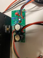
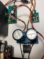
I've built the hi-fi headphone amp from Rod Elliott (project 113) and it sounds great (measures very well in LTSpice as well), however, I didn't get around to matching the BD139 and BD140 output transistors. I realise that it's probably unnecessary and doubtful that I'd ever hear a difference, but I decided it would be nice to do.

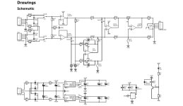
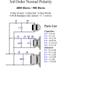
I found a thread (now closed) discussing this in which a matching circuit was offered by kct (I have attached the PDF here, I hope that's OK).
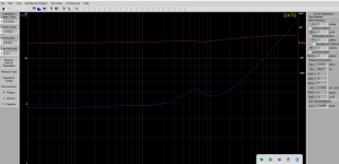
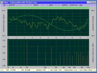
My question is that I have modelled this in LTSpice (attached), and whatever random transistors I pick, I still get well below the suggested 20 ua, so have I done something wrong in my simulation?
I'm sure that LTSpice must deal correctly with transistor gain and from what I understand (not a lot, unfortunately) the circuit appears fine.

So, I'm a bit baffled and left wondering if it's worth building it. Any comments, insights or advice would be very welcome 🙂

Attachments

Introduction!

Dear all,

I am an IT professional and repair and restore vintage hifi equipment in my spare time. I am quite passionate about this! I learn from every project on my bench and love to share my knowledge and experience with others. I document every project with pictures and stories on my facebook page. I hope to learn a few things from you here!


Have a great day,

-Jan

How to create .zma and .frd files from DATS V3

So I started with XSIM for a 3-way project.
I just took a on-line calculator for filter and started to pluck in the components in XSIM.
Realized I didn´t set the drivers specs - allthough it looked fairly ok with 8 ohm setting.

I don't have the graphs on the driver and I don't seem to get the exact graphs I need from Dats V3 as show in this video for FP Graph Tracer.
Login to view embedded media
So I wonder how do go about with Dayton Dats V3 to get the right curves and data I need to create accurate .zma and .frd files?

For now everything is really wacked when I put in what I have and can get out from Dats regardin .zma and .frd.

Attachments

Recommendation for Test Speakers

I built an F5m amp and used an old pair of infinity bookshelf speakers for testing. I inspected them and the foam just disintegrated when I touched it. I need new test speakers.

Does anyone have suggestions on the cheapest/best minimum test speaker setup? I was just going to buy pawnshop speakers tomorrow but am now thinking I should ask since used/blown/old/defective speakers could harm the amp? Since they will only be used for testing, is there something simple I should get like a car speaker or desktop PC speaker? If I buy used, I would need to test the speakers first. ( chicken and egg ) I guess I need something geared for testing and that will be 'easy' on my amp during testing. ( unlike my blown 30 year old infinity speakers )

I though I should ask before I buy, since I don't want to cause damage during testing. Also, someone may have ideas like incorporating dummy load resistor with a switch.

ICEPower 300AS1

Hello there,
I've built a guitar amp using an ICEPower 300AS1 module for the power amp. The pre-amp is a simple op-amp circuit, which is powered from the ICE module's 12V rails. The amp worked great until today. Today, the two status LED's from the ICE module are flashing quickly and there's no output from the ICEPower module. Checking voltages indicate that the 12V rails are at 1V. The 54.5V rail is good. Any thoughts on what could have happened to the 12V rail and why the LED's are flashing? Flashing is not discussed in the product datasheet. Thanks for the help. Cheers.

Audio Transport Module York

Hello DiyAudio community,

I wanted to share my audio transport module project called York.


Original Concept:
I personally used the Amanero modules for my audio devices and never had any problems with drivers or it's hardware, so I bought licenses for integration in my projects a while ago.
The main disadvantage was lack of possibility to communicate from PC to, for example I2C port, for sending configuration to audio DSP. There was only I2S audio stream. So my first idea was just to have USB hub on board to connect VCP IC. As the ESP-ADF was released, the idea evolved into creating a versatile audio data transport module with wireless interfaces, aligning perfectly with the ESP32 module configuration.
So, this architecture was born:
photo1701172546.jpeg


Hardware Features:
USB Audio interface (44.1-384kHz stereo)
BT AptX Audio input (in I2S slave mode)
FPGA reconfiguration (by ESP32 - no need for external programmer)
Amanero compatible interface

The device includes a module for AptX Bluetooth audio, addressing the ESP32's lack of support for high-quality codecs.
While the hardware might seem overkill with an 8K FPGA, it provides ample room for experimentation and DSP capabilities. It is very nice for experiments and hardcore DSP fun! 🙂

Photo of the first revision:
photo1701172519.jpeg

The BT module is underneath:
photo1701172519 (2).jpeg


Currently Implemented Features:
Web interface
mDNS service
MP3 stream playback (Web radio)
CLI for ESP control, FPGA, and external DSP register access
OTA firmware update (both FPGA and ESP32)
Analog Devices SigmaStudio support for ADAU DSP (configuration/control via Wi-Fi)

Later I've discovered ESP32-Squeezelite project, and it is a perfect fit for this hardware, adding Squeezelite, AirPlay and Spotify playback capabilities to all of the above.
I had to do some modifications to original project to include all the nice features that were developed separately for this module.

Hardware Evolution:
It is clear that the current hardware does not make much sense cost-wise: it needs an MCU for Amanero, an Amanero license, USB HUB and USB-UART chips.
Amanero MCU also requires an FPGA. Yes, the FPGA handles all stuff related to I2S multiplexing and clock generation, but all these functions can be implemented with one chip.

So for future version I'm going to use PIC32MZ MCU for as USB-I2S transport combined with VCP. That will consolidate four ICs into one MCU and expanding USB audio to support 8 channels (it can support both In and Out, maybe for future evolution)
I have a prototype of PIC32MZ module based on firmware developed by Alexey (Dortonyan) posted on Vegalab forum.
photo1701172519 (1).jpeg

Here's a photo of the hardware in my 4 (8ch) Class-D amp with ADAU1452 DSP (probably worth another topic)
photo1701172605.jpeg

As there are so many features, I'd like to hear on which are the most interesting ones for the community, I can expand more on them.
I'm eager to hear your thoughts and suggestions as I continue refining and expanding this project.
My vision for now is to make a new revision of the PCB with ESP32 + PIC32 + BT AptX module.

As for the firmware I'm going to fork ESP32-SqueezeLite.

Best regards,
Vladislav

X150.5 testing and planning for the future

I recently acquired a nice X150.5 and of course the first thing I did was popped the hood. Man, what a beautiful layout and build quality! This is a 2011 build date and I don't have much use history. It sounds beautiful with my Dunlavy SM-1's and I measured 45deg. C. heatsinks after a few hours. I plan to test the voltage drop across each of the output resistors (0R47) to test how matched the output sections are. Looks like 4 sections of 5 pairs per bias quadrant. My questions relating to testing, preventative maintenance and planning for the future are as follows; 1. should each of the measurements only have to match each other within the quadrant or should they match for the entire channel? Seems like that could be the reason for 4 bias pots... 2. I have read MOX resistors have a less reliable duty cycle and wonder if replacing the Panasonic ERX would be prudent? I could not find a life expectancy on the datasheet... I see Digi key has a reasonable supply of the ERX 0R47 and 3.3K type S 3w in stock so to plan for the future, I'm going to buy 100 of each unless otherwise advised. 3. Why is 50deg C is the optimal operating temp for SQ? when I measure Vgs for a new IRFP240 at room temp. I get about 3.15 V, then after sitting on the radiator, 3.0 V. Is the mosfet quieter at 50deg C or does the resistor TC curve come into play? 4. Should the needle on the bias current meter be vertical and sitting on the circle ? And lastly, when the PSU caps give up their life, 25 mm 40v caps seem to be un-obtainium... and I didn't see any R between and of the C's... I'm not opposed to re-imagining that PSU pcb if for no other purpose than to fit 30mm caps.
Peace
IMG_20230126_124019442_HDR.jpg
  • Like
Reactions: Russellc

SissySIT - kit packages

Presenting thread HERE


Schematic and pcb screenshot post #1 , plenty o pictures after .

Tips and Tricks thread HERE

Reading entire thread is advisable , same as inquiring any technical question there : Be sure that you are aware of all things electrical and mechanical !

THF51-S still available on fleabay , watanabetomoaki confirmed seller , also pras1701 - being member here and you have some discount vs. fleabay price

instead , pretty much sure that 2SK180 will work too

Pcbs are made for UMS , mounting directly to heatsink (will show you how).

NB that pcbs are common for SissySIT And Babelfish M25 amps , differences being really minor , except upper output device .

Do not hurry - read , think , ask and only when you feel that you want it and can make it , proceed ...... advice which I'm finding applicable on practically anything 😉 .

For anything else , write either here , send PM or directly to >zenmodiyaudio@gmail.com<

Prices are mostly dictated with small scale nature of operation (as always is case) and time/work involved in matching and soldering little buggers.

For ordering , contact me at above written e-mail addy .


Kit options :

1.
- LCH pcb ,
- RCH pcb ,
- all smd buffer JFets presoldered ,
- Hall current sensing chips presoldered ,
- surrounding smd caps presoldered ,
- 4pcs of 1uF MKC caps (for critical signal position) enclosed.

Full price , including Paypal fee and P&P for registered shipping all around the Globe - 130E

2.
- LCH pcb ,
- RCH pcb ,
- all smd buffer JFets presoldered ,
- Hall current sensing chips presoldered ,
- surrounding smd caps presoldered ,
- 4pcs of 1uF MKC caps (for critical signal position) enclosed.
-all multiturn trimpots
-output P channel mosfets , 2 pcs , most likely Infineon IRFP9140
-voltage regs
-cascode bjts
-optocouplers
-all electrolytic caps (all Panasonics ,except Elna Silmic II for 1 signal route position)
-one-pin sockets for special resistor positions
-all (MF 600mW) resistors
-small u22 caps for Borbely WC follower , if you want it for more sugar

to recapitulate - everything what goes on pcbs , excluding signal xformers and pcb/mosfet mounting screws/nuts/washers and , of course , excluding THF51-S

Full price , including Paypal fee and P&P for registered shipping all around the Globe - 175E


If I have everything in drawers in moment of order , can ship in 3-5 days ;
If I don't have any of normal parts in drawer , shipping could be delayed up to 3 days;
If I don't have pcbs in drawer , shipping could be delayed up to 7 days;
If I don't have most critical part for getting in my neck of wood - ACS Hall chips , shipping could be delayed up to 3 weeks.

DiAna, a software Distortion Analyzer

Now that all the RTX 6001 have been shipped (and delivered?) it seems to me the right moment to "go public" with a free demo version of DiAna. For those who never heard of DiAna, it's a software tool (in conjunction with a ASIO sound card) to measure distortion (THD+N and THD-N). The pro version also measures IMD and the frequency response. Furthermore, the demo version is a bit crippled in that recording of the signal and data processing has been slow downed (i.e. separated into two steps). As an example, please, see below the loop back results of a Lynx L22 sound card.
As for the lower part of the pictures:
1st. graph: Spectrum of the harmonics only.
2nd graph: Full spectrum with coherent integration (averaging).
3rd graph: Full spectrum with incoherent integration.
As for the upper part all pictures: green is input signal, yellow is residual.
(the height of upper and lower part can be varied at will, of course)
For more details, please send a PM.
Cheers, E.

Attachments

  • THD-harm.jpg
    THD-harm.jpg
    100.7 KB · Views: 5,145
  • THD-coherent.jpg
    THD-coherent.jpg
    113.7 KB · Views: 5,124
  • THD-incoherent.jpg
    THD-incoherent.jpg
    111.3 KB · Views: 4,932

Passive Crossover Yields Strange Result with Capacitor------Thoughts?

I have a 3 way build, but here we're only discussing the mid-range. It's a scan speak 18M4631 in a 14 liter sealed enclosure. Near field measurements here show the raw (no crossover), active 2nd order high pass filter at 200Hz, Passive capacitor (1st order) and the impedance of the speaker in box with no crossover. When I add a single capacitor (150uf) I get a massive resonance centered at 92Hz (red measurement), which is pretty much where the box seems to have an impedance spike. Is this normal? It clearly doesn't happen with an active crossover. It seems to get better with a 2nd order passive filter, but I can't get the slope correct with that and it's causing other problems with the linearity of the driver. Would a sizable amount of stuffing in the box help with this? I've seen this before with other speakers and I'm puzzled.

Other notes:
Scarlet interface, Earthworks M30 microphone with calibration file, Buckey Hypex Ncore Class D amplifier.
Blue measurement is raw nearfield
Orange measurement is active crossover nearfield
Red measurement is the questionable one with a single capacitor high pass filter. See the 92Hz centered increase?

Attachments

  • Scanspeak 18M.jpg
    Scanspeak 18M.jpg
    109.8 KB · Views: 42

Q: 6SN7 Cathode Follower Driver Idea for PP KT88/60W

Hi, folks,

I have a direct-coupled 6SN7 cathode follower driver idea for push-pull KT88 / 60W output. Not made any THD simulation, just basic schematic/simulation in LTSpice with voltage/current/bias numbers. This unit requires (-150V) supply apart from HV B+/6.3V. Cathode follower solves one of the fundamental problems of fixed bias push-pull stages with RC coupling.
P2 33K trim potentiometer is for controlling bias voltage, P1 10k - balance.

Any ideas or suggestions are very welcome. LTSpice files attached as zip archive.
Thanks in advance.

Attachments

  • Screenshot at 2024-11-06 00-32-16.png
    Screenshot at 2024-11-06 00-32-16.png
    75.9 KB · Views: 344
  • CF-Calc2.zip
    CF-Calc2.zip
    4.1 KB · Views: 62

SE 2A3 300B amp or what's ?

hello, following my E80CC 2A3 preamp, I took the same principle to make an amp,DRD.
just the right transformers and the 6C45Pe as input on 200H 30mA plate choke
the swing will be done
and way not... headphone output,
and way not ... XLR line outputs to drive a high power amp???
the signal-to-noise ratio allows it thanks to the 6C41C triode regulation of the HT @550V
which is perfectly comfortable thanks to the progressive raw HT rise delivered by an EY500A EI nos nib.
yesterday I listened Bob Dylan on HD800 sennheiser headphones, uahoo the clarity and the softness,
then on the fostex 208 BLH a deep bass already at low volume!
exceptional linearity from 15Hz a straight line
right now I'm listening in preamp mode driving PA amp 16X lateral mosfet exicon 25N/P10 i took of my Chevin 1500 that I modified, (replaced the power supplies for less voltage and more bias)
on my onken 2X15 bass guitar cabinet and two compressions from 1K2 KHz passive filtering
it's almost mono because only one cabinet, we're having fun, we're testing,
but let's get back to this amp....preamp???? or headphone amp????
as power amp we largely exceed the 3W5 that the 2A3 usually delivers,
the direct coupling provide grid current control for few more watts without abrupt distortion
as like on a classic assembly with a coupling capacitor and high value grid leakage resistors
the sinusoid is without visible distortion at 6V/8ohm with a 2A3 monoplate (I prefer).
if the final use is power amp, the transition to 300B is simple
replacement of the two 3.3V 25W meanwell for the 5V25W smps modules heating and modification of the grid cathode polar resistors
the power supply transformers deliver 600V 150mA and the first capacitor after 4X4 diodes 1uF 1KV MKT and after the EY500A slow polarization valve 10uF 1KVolts oil, no stress
the smooting choke 10H 200mA
the two filtering chokes 10H 90mA each
the output transformers allow 100mA
who nows tomorrow wath to decide, or not????
showing original E80CC 2A3 inspiration pream schematics

Attachments

  • alimentation synoptique.jpg
    alimentation synoptique.jpg
    61.6 KB · Views: 163
  • PREAMPLI 2A3 synoptique.jpg
    PREAMPLI 2A3 synoptique.jpg
    68.4 KB · Views: 159
  • Like
Reactions: huggygood

Attempt at a variable pickup mic preamp

Heya! Quick warning - I'm completely new to both all this audio stuff, as well as circuit design! So much of what I'm doing is complete guess-work. That aside, I'm attempting to make a little circuit that will go into a USB audio adapter off amazon (decided that I'll figure out microcontrollers next time).

Here's my problem (again) - I have no clue what I'm doing. I'm hoping someone could take a quick glance at the schematic to let me know how far off I am (I still don't know how true condensor capsules are meant to be powered). It would be reallyyy helpful if you could!

Here's what I've come up with, and the full schematics are also here for anyone who wants to try spot any stupid mistakes. Thank you for your time!

1733468988447.png

Note: SW2 is to ground the IN- when SW1 is set in either cardioid or figure-of-8. Andd I'll be using a capsule with 2 diapraghms (aliexpress RK-12)

Arcam Diva A90 inputs preamp issue

Hi,
I have a problem with the preamplifier inputs. This unit has 5 inputs. AUX, CD, TUNER, AV, DVD, but only two of them send a signal to the main amplifier - TUNER and AV.

I replaced the 2 main multiplexers Z104 and Z105 but it didn't help. There are resistors of 22kOhm each at the Z104 and Z105 inputs. An interesting fact is that when I set the TUNER input, the audio signal does not enter the 22kOhm input resistors, but the amplifier plays correctly, the signal comes out of the preamplifier, but when I set the CD input, the signal passes through the 22kOhm resistor and goes to the Z104 and Z105 input, but the signal does not come out of the preamplifier.

This seems illogical to me. 😒

Regardless of which input I set, the output signal does not appear on pin 8 of the Z104 and Z105 multiplexers, which is the signal output.

20241205_134205.jpg
Z104Z105.JPG

Attachments

Alto TS115 TrueSonic cutting out when ran for a while...

I know these are dirt cheap speakers and in all likelihood, they're toast, but I am going to see if I can give repairing them or doing something with them...

Cut a long story short, I ran them both too hot once about 12 months and they've both never been right since and both took a turn for the worst yesterday. After around 20 minutes, the sound went extremely hollow as if only the highs were coming through and most of the bass and mids were completely lost. The singer did an absolutely wonderful job of carrying us considering we had absolutely nothing coming through.

I backed the them off significantly and while one of them made it through just about (at about 70% volume), the other was really struggling and by the end was at around 30% and was still struggling to run for a few mins without losing all of the mids and bottom end.

I spent some time today and stripped them apart expecting to find a nailed preamp, but there's really nothing to indicate any damage. I read a couple of forum posts about the zener diodes going but they look fine. I've dug out the power amp on one.... again, it looks fairly normal. There's nothing to indicate it's toasted or any damage.

My gut feeling was the preamp at first but then it feels like the 20 minute delay might be something heat related.... which would be more likely the power amp right?

I have Googled.... and asked ChatGPT.,... in case anyone thinks I haven't tried yet 🙂

LM3886 Composite amplifier on eBay

[ :cop: Account banned, as it is the return of a previously banned account. ]

Hey guys,
A week ago I found this on eBay - https://www.ebay.com/itm/334842335447
I was wondering if anyone else had already tried that kit, but couldn't find anything.
So I ordered it and it came 3 days later. The seller also offers a "PCB version only" but I skipped it for now.
As other composites that I have this one also needs +/-15.0V for the op amp. The eBay seller offers such a PSU for a reasonable price so I got it as well.
I put up a setup and made some initial measurements. Picture 1 and 2.
Output power around 65W@8 Ohms PSU -> +/-34.0V. Picture 3
Output DC (input shorted) - 1.1mV - not bad at all. Hooked to a speaker it is dead silent.
The composite is stable and does not show any signs of oscillation though it lacks a Zobel network.
I tried to measure the THD using my Scarlett 2i2 (4th gen) but the threshold of -106dB was too high. Sounds very promising 🙂
Picture 4 Scarlett 2i2 THD and picture 5 composite THD @ 1W measured with Scarlett 2i2.
I'm going to dig out my notch filter and low distortion 1kHz oscillator to finish that job.

So more measurements are coming.

Attachments

  • LM3886.JPG
    LM3886.JPG
    663 KB · Views: 143
  • LM3886_test.JPG
    LM3886_test.JPG
    689.1 KB · Views: 139
  • LM3886_8Ohms_output.JPG
    LM3886_8Ohms_output.JPG
    819.3 KB · Views: 124
  • Scarlet2i2-4th.jpg
    Scarlet2i2-4th.jpg
    138.8 KB · Views: 126
  • LM3886_comp_1W_scarlet2i2.jpg
    LM3886_comp_1W_scarlet2i2.jpg
    140.3 KB · Views: 143

What is this kind of amplifier topology is this?

Hi!
I have a former college that has revived an old amplifier design he thoughts out may, many years ago. The design is highly unusual, where the output stage is "driving the power rails". In the pictures I've posted of this design he is using two 9V batteries as the power source. However, his old design used a +-50 or 60V power supply, and had loads of power. It sounds really good and has very little distortion. I think he's about to make a youtube video about it (the last design he uploaded created some discussion on this forum), so I'll post the video here when it's ready.

I happen to have an old Altec Lansing 9444B power amplifier (manual and schematics here), and I believe this is design around the same principle. It is a two channel amplifier, but it has two secondary transformer windings, two bridge rectifiers and dedicated smoothing capacitors for each amplifier channel. The neat this with this amplifier is that the all the output transistors, both NPN and PNP are connected to the same heatsink without any insulators, and the heatsink is grounded. Apart from this, I don't know why this design is preferred over the more usual ones.

So here are the questions:
  • What is the benefits of a design like this, compared to the more traditional push-pull designs?
  • Have something like this been done by someone else, other than Altec Lansing in the early 90s?
  • Does this design or arrangement have a name?


Simplified_schematic.jpg


Full_schematic.JPG

Replacement for IRFB4227

Hi.

I have a Behringer NX3000D with a blown output transistor (IRFB 4227). They seem to be impossible to find anywhere else than Ebay and i think they are just counterfeit parts.
Does anyone know a direct replacement i can use which i can source in Europe through Farnell, Elfa, Mouser or Digikey for example or does anyone of you have 2 spares lying around collecting dust? I can find a IRFB4227 in stock but it has other parameters such as Vds, rise and fall time etc. so I guess it won't work with that?

Thanks in advance!

Point of diminishing returns

Hi Thanks for reading What do you think is a fair price to pay for a quality drive unit before it gets into the territory of rapidly diminshing returns.
Recently I had to chance to audition a load of speaker cables. The most expensive was van den hul at £50 a meter which sounded no better / revealing / detailed than my current cable which is van damme at £7 a metre. Van den hul has been selling for years worldwide, what are these people paying all this money for
With drive units, some people post that they purchased a visaton drive unit for £100 and it sounded fantastic, others post they purchased seas excel for £700 and it sounded brilliant.
At what point does it get to when a drive unit is well made enough that it can give good performance and spending a ton of money more would give little benefits

Amplifier Mackie

Hello. I have a probleme with amplifier mackie m2600. Chanel 1 was bad, i change all 16 output transistors and 8 drivers. Now he is ok, but 2 output transistors is very hot. I buy the transistors from Mouser. I don t know what could be the problem. Thanks.
The schematic https://forumpoweraudio.ro/download/file.php?id=1269&sid=21f29696cc578af9c87b8b32871c002e


https://imgur.com/a/hIPRigZ here is a picture with hot transistors and some voltage measure.

Beogram CD3300 not playing sound

Hello, I have a Beogram CD3300 that does not play the CD’s.

It’s behavior is as follows for all CD’s. It spins for a while and does not read the TOC and displays the symbol ?

I have the service manual and test equipment available but it does not tell me how to get access to the component side of the PCB’s. I guess the problem is related to laser focus or power. Could anyone shed some light?.

I have replaced the gearwheel and belt on the glass plate drive and wonder what the correct sequence of events shall be.

When i push eject the plate is lifted about 15mm and then the drive starts slipping due to some light obstruction at the eject switch mechanism which is easily overcome by my finger assistance. The glass plate will raise to a near vertical position to allow me to insert the CD. Pressing “play” lowers the glass plate to close and bounces about 4mm up when touching the deck and settles in the normal closed position after which the CD starts to turn a very little bit in the wrong direction after a second it will turn correctly sometimes for a few seconds, sometimes for a lengthy period of time but no display of the TOC. When the disc spins I can step the tracknumbers as indicated on the display but no sound and finally it stops displaying the dreadly ?

I noted this model has a built-in test routine by applying a ground to pin 4 of the IC6078 on the control panel pcb and simultaneously applying mainpower to start the routine. Question shall pin 4 remain at ground during all tests?

Building a simple source selector

Hi Guys,

I am sure not to be the only one who doesn't have enough inputs on his amplifier. For my "office" setup I am using a Pioneer SA-508 that I have restored. But with tape, reel too reel, tuner, CD player and Mac I am short of at least one input.

Trying to get away with the most simple passive design a possible. Found a switch that has one "output" and five "inputs". Each got two connectors. So that works for Left and Right.

But and thats the big question, I need to hook ground up together for all devices. Is that doable? Do I sacrifice on audio quality? Or is ground just ground and it doesn't matter?

Marantz CD 40 player, no-oversampling and tube output

Hi,

I am selling one upgraded Marantz CD 40 player.
Is in very good condition and the changes have been made are:
  • changed few capacitors from power supply;
  • the standard op-amps output stage replaced with tube output stage;
  • put in no-oversampling mode;
  • changed the decoupling capacitors of the TDA1541 DAC.

The price is 300 euro (shipping included). I can ship only in EU countries.

Please send DM for more details.
marantz cd 40 2.jpg

Attachments

  • marantz cd 40 1.jpg
    marantz cd 40 1.jpg
    267.5 KB · Views: 256

Help choosing between two amplifiers, TPA3251 vs. TDA7498

Hello, I'm new to the world of class D amplifiers and I'm looking for a good and cheap amplifier to connect to my PC through an Asus Xonar AE, to listen to mainly heavy metal, stoner metal, classic rock and progressive rock. Here in Brazil there are two models that interest me, so I'd like to know your opinion about them. I already have a good quality 36V 9.7A Mean Well power supply. Thank you.

https://www.amazon.com/XY-T220H-Amplifier-12V-36V-Bluetooth-Compatible-Modified/dp/B0DDKKCHM8?th=1
https://www.amazon.com/HIFIDIY-LIVE-TPA7498E-Bluetooth-Amplifier/dp/B0CHFMYHMS

Near full range BMR (Balanced Mode Radiator)

Hi All,

Something that night tickle your fancy,

images


In the next few months a very interesting driver will
become available from Wilmslow Audio in the UK.

Its a near full range BMR (Balanced Mode Radiator) :

http://www.music-line.biz/cms/fileadmin/pdf/wp_ovator_bmr.pdf

http://www.hificritic.com/forum/default.aspx?g=posts&t=469

Midband efficiency is not high, making bass driver choice and bass
loading type very interesting, there are lots of workable possibilities.

2x12" open baffle could be quite interesting.

Myself, I'm currently planning on building the TRK design.

/Sreten.

For Sale Fisher SK 492 50 SA 8.5K/W Heatsink - 18pcs

Here i have new heatsink that can be used for preamp, vas amp, headphone preamp heatsink and other devices that needs small size high quality heatsink from fisher.

Heatsink thermal resistance are 8.5K/W and i have 18pcs for sale.

Price is €6,00 per pcs plus shipping cost.

Length is 50mm, black anodized and in the middle from bottom side is thread inside heatsink for M3 screw so that it can be easy fixed to pcb.

Attachments

  • 1712730167841.jpg
    1712730167841.jpg
    170.6 KB · Views: 108
  • 1712729897327.jpg
    1712729897327.jpg
    276.6 KB · Views: 106

FPGraph Tracer : great software to create FRD or ZMA file from graphic response curve

i just started learning to use Xsim, it's easy and fun to learn. but I'm lack of having frd or zma files from the driver that i want to simulate. Somehow i landed on this page

FPGraphTracer : fprawn labs

"FPGraphTracer is a simple, easy to use, tool for automatically tracing lines in a graph to extract the data it represents. Originally intended for the DIY speaker community, it outputs in the FRD/ZMA text based format used by many speaker designing programs, which can also be pasted directly into most Spreadsheet software"

long time ago, i have tried manual tracing from manufacture frequency response curve, copy it to xls file and estimate SPL based on Freq. this is manual sampling but it's very hard and boring to do to match with datasheet.

I have abandoned this method and now i'm surprised to find this wonderfull software which fulfill my needs. you can read the manual on the page, but I'd like to share my experience here, hopefully it's useful

1. find manufacturer frequency response curve in high resolution, i prefer pdf file instead of jpeg.
2. convert pdf to to png (many free website to do this for free). this why step 1 for pdf is better because JPEG file has dirty image around the line. the "white" on the screen you see, when you zoom it will show many artefact
3. load png file from step 2 to FPGraphTracer, click 8X zoom button and zoom to the line that you want to trace. once you click it, look at the trace that it created (usually in pink line). if you find it hard to get a good curve tracing compared to datasheet, go to step 4.
4. edit the png and clear any dots around the curve that you want to trace, the purpose is to get a clean curve without any artefact. I do this using MS Paint, zoom it to max 800% and start Erasing pixel by pixel

this is my project to trace SB17NRX, all artifact around the curve have been cleaned. started from Axis response

960735d1624017760-fpgraph-tracer-software-create-frd-zma-file-graphic-response-curve-sb17nrxc35-8-axis-png


5. repeat step 3, move vertical and horizontal pink line to match with graphic and set X and Y axis min/max on left menu. my below example, vertical line is set to 60 and 95 (this is for SPL) and horizontal line to 20 and 15000 (this is for Freq). then save to .frd file. there are 3 group of data, first is Freq then followed by SPL and followed by Angle

960737d1624018415-fpgraph-tracer-software-create-frd-zma-file-graphic-response-curve-trace-1-jpg


6. data verification, this is the most important step. open frd file using Notepad, choose any Freq point on graphic and compare to the number on frd file. my below example is : choose 100Hz point and check on number that is shown as 88 which verified by my eyes to the graph is around that, mission passed. you can sample as many point as you need

960738d1624018415-fpgraph-tracer-software-create-frd-zma-file-graphic-response-curve-trace-2-jpg

Attachments

  • SB17NRXC35-8 - Axis.png
    SB17NRXC35-8 - Axis.png
    217.6 KB · Views: 6,155
  • trace 1.JPG
    trace 1.JPG
    218.7 KB · Views: 6,099
  • trace 2.JPG
    trace 2.JPG
    254.5 KB · Views: 5,505
  • Like
Reactions: stretchneck

Do current mirrors make the sound "grainy"?

Hi!

Newbie here! I recently started dabbling in amplifier design. What an addictive hobby! I've learned more than I ever could have imagined.

Anyway, I put together the amplifier in the attached schematic. It's fairly basic and classic design. I like the way it sounds and I get respectable values in both simulations and real measurements. So far, so good!

However, I was recently told to lose the current mirrors on the LTP by someone (who's probably on this site, so feel free to chime in). The reason was that they supposedly make the sound "grainy". I tried to replace the current mirrors with 2k resistors in SPICE and it increased my THD from 0.004% to 0.15%. Suffices to say I wasn't impressed.

I guess my question is whether there's any truth to current mirrors having a detrimental effect on sound. I'm here to learn, so lay it on me!
1733404239750.png

Kenwood KR2010 FM noise mute

Hello everyone. I am continuing with the restoration of a Kenwood KR2010 receiver.
I have managed to correct the bias current and the DC bias of the power stage thanks to your contributions.
https://www.diyaudio.com/community/threads/kenwood-kr-2010-bias-adjustment.371991/
I have put LED backlighting on the tuning dial and illumination on the tuning pointer.
Now I want to reduce or eliminate the noise between FM stations, and looking in the service manual I see the IC KB4402 and I don't know how to achieve it since there is no potentiometer to adjust the mute. I appreciate your help.

Attachments

  • KR2010 diagram.pdf
    KR2010 diagram.pdf
    6 MB · Views: 58
  • KB4402.jpg
    KB4402.jpg
    182.5 KB · Views: 68
  • Screenshot_2024-09-30-22-08-58-972_com.miui.gallery (1).jpg
    Screenshot_2024-09-30-22-08-58-972_com.miui.gallery (1).jpg
    125.9 KB · Views: 56

Amplifier suggestions for 300W~350W 4Ω tower speakers

Hi there,

I'm new here and don't know if any better place to ask here.

I'm looking for an amplifier to build that can drive my custom made 300W 4ohms floor standing speaker,

I'm looking forward to Apex A40 design,
Any updated or better suggestions?

Thanks in advance

(Attaching A40 schematic)

Attachments

  • APEX A40 SCHEMATIC From Directory of Apex Audio Thread.JPG
    APEX A40 SCHEMATIC From Directory of Apex Audio Thread.JPG
    221 KB · Views: 189

First post

Hello

I've been following many threads on this excelent site for years, but never posted anything yet.

My interest for Hifi and audio goes back to being a kid and listening to my dads Stereo setup a beautiful
Marantz reciever, Dual turntable and big Sansui speakers 🙂 This is almost 40 years ago now...

Since then I have owned many bought Hifi setups and built quite a few DIY speakers and subwoofers. Hopefully
I'll be able to build many more and keep on learning.

Negative Feedback

This isn't a strictly tube question but since I'm asking in the context of tube literature I decided to post here. I've attached a copy of an explanation of the effects of negative feedback from a 60s RCA Tube Manual.

My question is this: As I understand from the manual's explanation, the reverse phase signal is fed back to the amp input cancelling the peak as shown. This seems like a paradox to me thoughif the unwanted signal is being cancelled constantly, how can it appear at the amps output in the first place?


feedback.png


thanks

Mitch

DIY speakers- I need crossover help to finish this project… please!

I just picked these up at junk store, they are seriously well made, but have no crossovers or terminals. I need help in finding the proper crossover/terminal given the speakers.

tweeters are “Dali BC25tg19-04, DPE9.” They measure 3.3 ohms

woofers are “Peerless HDS-P835025, 8ohm (measure 6.6) 55 watts t04-1B06B0009 2018.09.24 made in china”
any help appreciated As I have no idea what I am doing!

Attachments

  • IMG_4294.jpeg
    IMG_4294.jpeg
    453 KB · Views: 107
  • IMG_4295.jpeg
    IMG_4295.jpeg
    412.5 KB · Views: 89
  • IMG_4299.jpeg
    IMG_4299.jpeg
    482.4 KB · Views: 87
  • IMG_4298.jpeg
    IMG_4298.jpeg
    367.4 KB · Views: 88
  • IMG_4297.jpeg
    IMG_4297.jpeg
    409.4 KB · Views: 95
  • IMG_4296.jpeg
    IMG_4296.jpeg
    371.2 KB · Views: 99

Mini-MEH🤷

Day1
Goal: Small reliable all in one "pa" speaker for friend.

Notes--I chose the drivers for the flat "cones" should negat the need for any chamber fill magic that I don't have the tools or skills to create.
--i will probably be make the cabinet out of nomex honeycomb and fiberglass.

Elements
X1 DaytonH6512 waveguide
X4 TECTONIC Tebm35c10-4 BMr 2"
X2 Dayton rc180-55 res-core race track woofer
X1 1" dome tweeter TBD (I might start with whatever cheap I can find local)
X1 wondom Jab4 4x30w dsp amp (2x30w 1x60w)
Optional
Battery bank

Approx $250 total


To start looking for advice on how to mould/glue on mounting plates for mid and woofer

I'm thinking Bondo from what I have seen


1000003306.jpg
1000003308.jpg
1000003309.jpg
1000003310.jpg

Login to view embedded media

[3D Print] BJT Simple Matcher - Air Current Shield

Attached is a 3D print file for a little box to be used as an air current shield when matching BJT transistors using @Mark Johnson 's BJT Simple Matcher.

Very simple design, but it fits snug and helps with consistent measurements.

This part will be included in all of the BJT Simple Matcher kits that are posted up in the swap meet.
20241207_195127.jpg

20241207_192757.jpg

20241207_194854.jpg


1733629020169.png


Added thicker walls to minimize thermal transitions that I was seeing with the thin walled version.
1733683620100.png

Attachments

DIY MIDI 6x6 Janko accordion

It was always my ambition to create an easy to learn and play accordion style musical instrument, but it took me ages to get my act together. Finally, step by step I built the DIY components for it: Result:
1) I converted a 120-button accordion bass to Midi.
2) From 3 PC plates I created a 6x6 JANKO keyboard
3) I created a WYSIWYG notation for it (similar to Klavar notation).
It can't get any easier (!!) and to make it sound like a real accordion I got myself the latest XXL MASTER ACCORDION from V3 sound modules, pairing it with an equally excellent MidiToolEx software and voilà, now I'm enjoying the sound of 206 top accordions at a fraction of Roland Midi accordion's costs.

In case anyone of you would like to have some more details, please feel free to contact me.
To accelerate the notation conversion I would need to find a programmer for it.

Attachments

  • Midi accordion.JPG
    Midi accordion.JPG
    142.7 KB · Views: 151
  • 1.jpg
    1.jpg
    136.8 KB · Views: 158
  • AccBass 1.JPG
    AccBass 1.JPG
    174.5 KB · Views: 135
  • 000.JPG
    000.JPG
    105.9 KB · Views: 135

[3D Print] ACA Mini - Murata Coil Box for "ClaudeG Mod"

Attached in the zip file below is the 3D print file (3MF) for the coil box I created to be used with ClaudeG's suggested modifications for the ACA Mini. Anyone with access to a 3D printer can print the parts out of PLA (or material of your choosing).

Use two tapered head M3 bolts (16-20mm long) to secure them top plate to the bottom. It's designed to tightly grip the barrel connector cable (little grip ribs are hard to see) so no stress is put on the solder joints.

I made up a bunch the suggested mod kits after reading his review which I posted up in the swap meet.
20241207_184600.jpg

If you purchase a 1 meter 5.5x2.5mm barrel dc plug extension cable like this one, all you do is simply access the positive DC wire inside, snip it, and put the coil in series. Clamp the wires tightly with the top plate and you can add/removed the coil easily for A/B listening comparisons.

Here's the little mini-Build Guide for how to install the coil in the box.
ACA Mini Murata Coil Build Guide (Rev 12-29-2024).png


20241124_115359.jpg

Attachments

  • ACA_Mini_Murata_Coil_Box.zip
    ACA_Mini_Murata_Coil_Box.zip
    595.2 KB · Views: 48
  • 20241124_115901.jpg
    20241124_115901.jpg
    484.5 KB · Views: 49
  • 20241124_120009.jpg
    20241124_120009.jpg
    489.6 KB · Views: 53
  • 20241124_115326.jpg
    20241124_115326.jpg
    592.5 KB · Views: 56
  • 20241124_115151.jpg
    20241124_115151.jpg
    399.1 KB · Views: 60
  • 20241124_115040.jpg
    20241124_115040.jpg
    449.6 KB · Views: 56
  • 20241124_114230.jpg
    20241124_114230.jpg
    487.1 KB · Views: 58
  • ACA Mini Murata Coil Build Guide (Rev 12-29-2024).pdf
    ACA Mini Murata Coil Build Guide (Rev 12-29-2024).pdf
    9.1 MB · Views: 48

Fostex DMT-8VL Mixer Channel dead?

I have just bought a used Fostex DMT-8VL and it has a dead Channel, I am trying to find some advice about what could be causing this?

I don't know anything about repairing multitrack recorders or mixers, I bought this item thinking I was buying a fully working digital multitrack but it turned out to have a few problems which I think after a closer look were caused by liquid at some point in its life, I noticed that all the faders were rough and giving inconsistent audio from the input channels, and channel 8 was giving no audio at all, I stripped the whole recorder down and gave it some TLC all the faders have been thoroughly cleaned channels 1 to 7 are perfect with consistent audio all the way up the faders and they slide nice and smoothly now, the only issue it still has is the silent Input Channel 8.

What I have tested so far
If I turn the levels to their limits I can just about hear the audio from input 8 but its very faint, if I switch the L/R-Mon switch to Monitor I can hear the audio signal coming in from the channel 8 jack and I can raise lower the volume and pan the signal left and right using the pots in the monitor section but the fader, eq and meters have no effect when in this mode so I suspect that the problem is after the Monitor section?

I used input 1 to send and record the audio signal to Input Channel 8 and the Channel 8 Led Meter responded to the signal and recorded the track but I can hear nothing on playback the fader does nothing to the signal yet the meter for track 8 is peaking away showing that there is a recording there?

The recorded output from track 8 cannot be heard from the stereo outputs but it can be heard loud and clear from the rear direct out for Channel 8 so I am assuming that the recorded track bypasses the channel 8 fader section altogether?.

So I am stuck without any schematics or previous knowledge on mixer repairs, I am hoping someone can put me on the right track so to speak?

Thanks in advance
Dale

Attachments

  • 20241202_010943.jpg
    20241202_010943.jpg
    354.3 KB · Views: 100
  • 20241202_010924.jpg
    20241202_010924.jpg
    232.6 KB · Views: 83
  • 20241201_143709.jpg
    20241201_143709.jpg
    468 KB · Views: 68
  • 20241201_143657.jpg
    20241201_143657.jpg
    596.1 KB · Views: 82

Using Rigol DS1054Z to set Amp Bias

I built an F5m amp and am now looking to tune the bias.

I tried using my Rigol DS1054Z with 2 leads across a resistor on the amp board ( lead ground wires removed ) at 1X ( and 10X ) with MATH enabled on Chan1 and Chan2 ( A-B ) but get lots of noise on the math line. The math line bounces around within a 200mV range which is not accurate enough.

Any advice on how I can use it to get a reading of 10mV or even 1mV accuracy? ( I think my Rigol is unlocked too )

I get a 10000 meter next week but wanted to try with my oScope in the meantime.

For Sale Hypex Bruno's Balanced Preamp PCB kits from GB, parts and Extra, All SMD Parts installed

FS Hypex Bruno's balanced preamp PCB kit with all small SMD parts pre-assembled on the preamp board from the original GB. Kit also includes all the parts (except XLR connectors). I have also a pair of original Hypex HxR12 Regulator modules to supply the preamp (POS & NEG), and optional Hans Polak design Volume controller (resistor/relays) that was designed for this project (there are some small smd resistors to solder on this pcb. It also includes the parts for the Volume control.

Includes all docs, schematics, detailled BOM, pcb silkscreen, etc...

So this kit is the perfect compagnion for any Hypex based amplifier, being designed by Hypex Bruno himself...

Price is 200U$ + shipping + 3.5% Paypal fee. Note: kit is small and not heavy, so shipping won't be that expensive

Let me know if insterested
SB

Attachments

  • 20240715_151133.jpg
    20240715_151133.jpg
    550.7 KB · Views: 239
  • 20240715_151119.jpg
    20240715_151119.jpg
    494.1 KB · Views: 243
  • Hypex Regs.jpg
    Hypex Regs.jpg
    73.8 KB · Views: 265
  • Bruno Preamp_Schematic.JPG
    Bruno Preamp_Schematic.JPG
    124 KB · Views: 255
  • Hans Polak Volume_Schematic.jpg
    Hans Polak Volume_Schematic.jpg
    73.6 KB · Views: 249
  • hp bruno potmeter 3.pdf
    hp bruno potmeter 3.pdf
    134.1 KB · Views: 81

Aleph-X standby mode

Hello,

I'd like to add support for placing the Aleph-X into standby mode where the output mosfets would not conduct any current. Standby would be active during initial power-on of the amps to limit inrush currents but could also be entered afterwards instead of powering off the amps (for short periods of time).

I plan on using an RGB (red in standby, blue during normal operation) momentary anti-vandal switch with associated circuitry (not shown) to generate the standby signal. On power-up, the standby will be active until the switch is pressed. Later presses would enter/exit standby mode.

In the attached schematic, the relay output provides a DISABLE signal that is at V- when in standby, or V+ (via current limiting resistor) when not. This DISABLE signal feeds several PNP transistors that conduct when standby is enabled and, in turn, disable the aleph current source mosfet (Q10) and the output gain mosfet (Q11) via the transistors Qa and Qb, respectively.

The schematic provides 2 options for disabling the output gain mosfet (Q11). The first options just sinks the current from the input stage differential pair. The second option disables the input stage current source and, I think, is along the lines that Nelson has suggested in the past.

Does anyone see any problems with the proposed circuitry? Are there any improvements that can be made and which of the 2 options would be preferred for disabling the output current gain mosfet, Q11?

Much thanks in advance!
Brad

Attachments

Hi there

I've just joined, my name's Will - hence "double U" in my username. I'm a qualified electronics engineer based in the UK with quite lot of experience in analogue professional audio - mixing desks, public address systems, sound reinforcement, radio & TV station studios, OB vehicles, etc. My passion these days is hi fi ... proper no BS hi fi with sensible amplifiers and clean signal paths. I don't do snake oil. I look forward to chatting! Cheers for now, Will.

For Sale Paradise phono amp sale of components.

I bought this group buy kit of parts from a diy-audio member some years back but it became surplus to requirements when a constructed unit appeared for sale.

Two heatsinks with power transistor clips
PCB hardware (pillars)
Main pcbs (R2)
Sealed static shielded bag of IC, power transistors and small sig transistors.
Small signal transistors BC337 and BC327 possibly matched.
I think for really close matching, an additional quantity of these may be needed to sort through.
Bag of resistors - mostly Dale, some higher power resistors and trimmer pots
Bags of electrolytic and other capacitors
Bag of green leds and other diodes
Calvin buffer pcbs with eight transistors. I believe some of these transistors are hard to source now.
I’ve thrown in some additional BC337 and BC327

I’m not absolutely sure every single component is there without unpacking and counting everything but this should be an intact set.
Thread here https://theartofsound.net/forum/showthread.php?22875-DIY-phonostage and also many threads here on diy-audio.
This phono amp is capable of bettering most commercial offerings if built with closely matched transistors in the amplifier stages.

Note - There are no parts for the pre-regulators (supply unregulated dc). It should be easy to source parts and boards for these.

\
I'm looking for £375 plus p&p or collect Shrewsbury. Prefer to sell to UK member but may consider international sale


Classe amp CA5300 keeps blowing outputs. Fault finding

Hi,

I took a parts unit of classe ca5300 amp. Its a 5 channel 300w amp. initially it was in protection mode because one channel had blown outputs. While doing the fault finding I accidentally (forgot that rail voltages were still there with unit off) plugged in PS wiring and sparks came up and blew that amp. Changed couple 82v zenar diode, MJD243/MJD253 pairs and all outputs. Over the period I have blown 7 pairs (10 transistor per pair pair). Each amp board has 5 pairs of 2sa1294 2sc3263 output transistors. Changed all including pre-driver mosfets. Most parts are still obsolete so have been careful to buy from reliable sources. Initially 2 channels were working and now one of them also blew. rail voltages and test points per Classe were correct and it biases to 1mv. Its a weird procedure but maintained the 0.3+/- mv. When I play music or sometimes just while waiting for biasing the outputs blow and unit goes into protection. So in all the unit can be biased and within around 10 mins the outputs blow. I even changed emitter resistors which measured fine. I am not able to find the root cause and not willing to blow more transistors which are obsolete. The last board that blew was had the original outputs and LME49810 chip. Not that I am doubting the purchased parts but if this went out then the root cause might be different. Now the common denominator is power supply. Today morning I measures the rail voltages and once I get 87vdc I monitored for 10 mins. It went to 87.5vdc and come back to 87.3vdc. I think this variation is acceptable. Then I removed the power supply board and checked the bridge rectifier which hardly fail. I didnt make full test but if the BR blew it wont give DC voltages that are close. Finally I see Four 5600uf 100v caps bank per rail which measures 17900uf. I think its just lower than 20% which should be 22400. I removed one cap and it measures 4600uf instead of 5600uf. ESR being 0.03 ohm. Anyway I think its at the lower end of 20%. I am not sure if this could be the root cause. I am lost so looking for some guidance on how to determine the root cause. I almost gave up but I know on this forum there are many experts who can guide me. Thanks in advance.

New Member with a Goldmund Studio table

Hi All,

I’m Mike and I’ve just joined the Forum from Vancouver B.C.

I’m looking forward to acquiring some knowledge from everyone’s previous experiences, particularly in regard to any Goldmund Studio suspension upgrades.

I’ve already read several great Threads on other subjects, and it looks like you guys are a gold mine of great information!

Thanks and happy listening,
Mike

bhjazz's BA2018 Ground Noise Problems

My initial posts are in the Wayne's BA 2018 thread starting on page 224 here: https://www.diyaudio.com/community/threads/waynes-ba-2018-linestage.329240/page-224

For the test table below, The VRDN units pictured will be named, Chuck, Alfred 1, 2 and 3 from the bottom up.
The bottom unit is closest to the front panel.
1 and 2 will power BA2018 channels right and left, respectively.
3 will power an Academy Audio ISS and MCU.
1 and 2 are set at +/-18V, 3 is set at +/-15V.

For now, the output transformers are disconnected.

TestResultsNotes
Add jumper for VRDN Denoizer circuitfailnoise did not change
Include ISS system / exclude ISS systemfailnoise did not change
Check that the screws attaching the PCBs to the chassis are not shorting the Ground on the PCB to chassis.failno screws appear to be shorting to ground.
removing the 3rd set of power wires from the Antek (going to the 15 VDC board) then checking the two BA2018s (CraigI59)failnoise still apparent in both channels
disconnect the wires from the VRDN to chassis (andynor) linkfail
noise still apparent in both channels
short BA2018 inputspasshelped a lot for single channel test
run a short fat wire between those two grounds. From the center of that short fat wire, connect the rest of the ground wires from the loads.. "T" style. (william2001)pass-ishTested a modified version of this by daisy-chaining ground connections to each other, then connecting the last VRDN to star ground.
gather those ground wires into one connection point, instead of leaving two inches between them as loop area. (andynor)pass-ishTested connecting each VRDN to the next VRDN, then connecting VRDN 3 to star ground. Knocked the noise down a huge amount. Still there, but possibly getting some open loop noise from the two longer VRDN-to-Star-Ground wires which are hanging around.
Will remove those and test again, but possibly on the right track.
Left channel run alone. Quiet or noisy? (benmah)passquiet
Left channel with right channel power supply, run alone. Quiet or noisy? (benmah)passquiet
add 0.1uF cap in parallel to 5 Ohm resistor (BH)
If lifting the chassis connections by and itself solves it, use a GLB. A simple resistor may not solve it. (andynor)
connect the two BA2018 halves’ ground sockets (andynor)
  • Like
Reactions: andynor

Constant curvature tweeter array

1658233147206.png


I have been thinking about a replacement for the high frequency section of our horn sound system. Currently we use 3 *40 degree 8+1” coaxial horns horizontally arrayed >400Hz (the top horn of this orbit top).

1658233162698.png


We already don’t use the lower folded horn instead using 15” midbass horns 100-400Hz: https://www.diyaudio.com/community/threads/mega-midbass-straight-horn-139db.349105/

Then above this I have been designing a horn for M200 midrange compression drivers ( https://www.diyaudio.com/community/...per-scripts-and-m200-fun.385493/#post-7003214 ). My plans have moved forward a little since this thread and I now plan on making this a dual driver horn covering up to 3kHz. I would like to mount a vertically arrayed tweeter array coaxial to this horn (at the mouth). This would be something like the Void Incubus which appears to use a constant curvature array composed of line array waveguides:

1658233192266.png


My aim would be 90 degree horizontal dispersion and 4-6 elements vertical so 10-15 degree vertical . However when I look at the data for a line array waveguide like the B&C ME102 I see that the horizontal is very wide and the vertical is not displaying constant directivity behavior (although is B&C quoting -12dB contour rather than -6dB?):

1658233231404.png


1658233240267.png

Yamaha DXS15 hello. Pcb Sub wy52900

Hello, i have a problem with my sub.so yes, I gave my amplifier to the service because it wouldn't turn on, unfortunately the servicemen weren't able to fully repair the amplifier, that is, the amplifier turns on after the service but two diodes start to light up: power and protection, then protect goes out and the limit starts to light up. The service stated that there was a problem with the control of the transistors, which overheat and then burn out and that they had a problem with the device documentation (whatever they meant) and that was the end of the service adventure. The amplifier is already with me and I decided to see what was actually happening. And it looks like the transistors are actually heating up and very quickly because the thermal imaging shows 70°C and that in 3 seconds. And that's without connecting music, just turning it on. I don't turn it on for longer than 10 seconds because I'm afraid that further damage may occur. I took a photo which. These are transistors Q414-314- Q413-313 and Q103-Q107. I also noticed that they decided to change the carbon resistors R344 and R345 to regular high-power resistors. Has anyone had such a problem with such an amplifier, or knows what steps to take to find the cause?

Attachments

  • flir_20241207T173611.jpg
    flir_20241207T173611.jpg
    49.4 KB · Views: 42

DIY Front loaded horn speakers

I am looking for some plans for a DIY pair of Horn speakers. I am thinking folded horn in a box with a dynamic conventional driver for the Bass. And then on top of that a good compression driver with a multiway horn or just a nice front loaded horn. I will be driving it with my 300B SET amplifier. A very high quality amp. I am looking for spl around 105ish to be on par with my La Scalas that these will be replacing. So I am looking for suggestions. Don't worry about cost at this point. Just toss out some suggestions of nice designs please.

Lurking from the shadows

Hello. I've been enamored by vintage audio for some years now, having amassed, much to my wife's deep consternation, a small collection of treasures. I love listening to it, looking for it, looking at it, polishing it (kidding / not really) and now finally slowly learning to fix it! The more I learn the more I realize how little I know. Amongst all of this I have become aware of and interested in primarily speaker building, starting with full range. I have yet to whet this new appetite, so here I am. Embracing middle age!
Projects by fanatics, for fanatics
Get answers and advice for everyone wanting to learn the art of audio.
Join the Community
507,556
Members
7,876,731
Messages

Filter

Forum Statistics

Threads
405,713
Messages
7,876,731
Members
507,556
Latest member
Syracusejim