You are using an out of date browser. It may not display this or other websites correctly.
You should upgrade or use an alternative browser.
You should upgrade or use an alternative browser.
Filters
Show only:
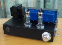
My Dynaco ST-70 with Bud Purvine designed transformers built by Kolarkar Audio
- By analogadikt
- Tubes / Valves
- 32 Replies
Hi all ,
Last few days I have been playing music through my revamped ST-70 and must say that I am very happy.
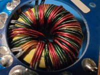
The biggest change is new OPTs that are designed by Bud Purvine of Onetics. Bud Sir has shared this with Asnain of Kolarkar audio research and he has built the new OPTs as per those designs. He also built new power transformer and a choke, both of substantially higher capacity than the originals. The power transformer has a 250V primary with a240V tap, this enables matching the supply voltage that is 240V nominal but climbs above that many a times.
The OPTs are a tad larger than the originals so we had to drill new holes in the chassis but the cover fits without any problem.
The old phenolic PCB was replaced with a new one that is based on the original schematic.
The GZ34 rectifier was treated with the "yellow sheet mod" to make life a bit easy for it. The selenium rectifier was also replaced with a silicon one.
I don't have a quad ofEL34 right now so I am running a quad of Sovtek 5881 that are sounding great.
Really enjoying this amp. Thank you Bud Sir and Asnain 🙂
Best Regards,


Last few days I have been playing music through my revamped ST-70 and must say that I am very happy.
The biggest change is new OPTs that are designed by Bud Purvine of Onetics. Bud Sir has shared this with Asnain of Kolarkar audio research and he has built the new OPTs as per those designs. He also built new power transformer and a choke, both of substantially higher capacity than the originals. The power transformer has a 250V primary with a240V tap, this enables matching the supply voltage that is 240V nominal but climbs above that many a times.
The OPTs are a tad larger than the originals so we had to drill new holes in the chassis but the cover fits without any problem.
The old phenolic PCB was replaced with a new one that is based on the original schematic.
The GZ34 rectifier was treated with the "yellow sheet mod" to make life a bit easy for it. The selenium rectifier was also replaced with a silicon one.
I don't have a quad ofEL34 right now so I am running a quad of Sovtek 5881 that are sounding great.
Really enjoying this amp. Thank you Bud Sir and Asnain 🙂
Best Regards,

Do I Need a Stereo to Mono Summing Cable/Circuit Between Pre-Amp and Equalizer for Subwoofer on Vintage Equipment?
- By Ron1200
- Analog Line Level
- 2 Replies
Hi.
I recently picked up a Klipsch subwoofer to add onto my vintage stereo system. My configuration is as follows: Yamaha CX-830 Pre-Amp > ADC SS-315 Equalizer > Phase Linear 300 Amp. I currently have the subwoofer's input connected between the Pre-Amp's Pre-Out and the Equalizer's Pre-In using a Y-cable on the LEFT channel only.
My issue is that the Klipsch Sub (Klipsch R-120SWi) uses a Klipsch provided wireless module. This module connects via a single RCA jack (either full range mono or LFE). I would like to send both Left and Right signals to the Sub. I like picking up the signal before the Equalizer and adjusting the sound at the Sub.
I am concerned that if I use a simple Y cable to bridge the left and right channels between the Pre-Amp and Equalizer, I will effectively make all signals mono. I've been doing some research and stumbled upon a summing cable/circuit that uses 1K resistors like in this image found on the Parts Express Forum. Also, Paul from PSAudio talks about this on YouTube but suggests 10K resistors.

My question: Should I use a stereo to mono summing cable/circuit between the pre-amp and equalizer to obtain the mono signal to send to the subwoofer? Or, is there a better way to do this that I haven't thought of?
If it helps, here are HiFi Engine links to the components involved:
Yamaha CX-830 Pre-Amp
ADC SS-315 Equalizer
Phase Linear 300 Series Two Amp
Thanks
Ron
I recently picked up a Klipsch subwoofer to add onto my vintage stereo system. My configuration is as follows: Yamaha CX-830 Pre-Amp > ADC SS-315 Equalizer > Phase Linear 300 Amp. I currently have the subwoofer's input connected between the Pre-Amp's Pre-Out and the Equalizer's Pre-In using a Y-cable on the LEFT channel only.
My issue is that the Klipsch Sub (Klipsch R-120SWi) uses a Klipsch provided wireless module. This module connects via a single RCA jack (either full range mono or LFE). I would like to send both Left and Right signals to the Sub. I like picking up the signal before the Equalizer and adjusting the sound at the Sub.
I am concerned that if I use a simple Y cable to bridge the left and right channels between the Pre-Amp and Equalizer, I will effectively make all signals mono. I've been doing some research and stumbled upon a summing cable/circuit that uses 1K resistors like in this image found on the Parts Express Forum. Also, Paul from PSAudio talks about this on YouTube but suggests 10K resistors.
My question: Should I use a stereo to mono summing cable/circuit between the pre-amp and equalizer to obtain the mono signal to send to the subwoofer? Or, is there a better way to do this that I haven't thought of?
If it helps, here are HiFi Engine links to the components involved:
Yamaha CX-830 Pre-Amp
ADC SS-315 Equalizer
Phase Linear 300 Series Two Amp
Thanks
Ron
2-way small(ish) active with Hypex FA
While waiting to finish my learning project (thread link) I am starting to think over what my next project could be. I must be enjoying it!
My mostly used current pair of speakers is Genelecs 6010A in the kitchen - these are playing almost all the time when we are at home. As you know these are very small, the smallest Genelec make - 3in mid-woofer, 25W amps, 20cm tall.
I was thinking to build a small sub to complement them, but another option could be making a new small (abt 35cm tall) 2-way based on a slightly larger (5-6in?) high-excursion midwoofer with Hypex FA122 or FA252. I also thought I could experiment with a box made from multiple 'slices/layers' of MDF, so I can work on them without a workshop and using only small tools on pre-cut small panels. I could even try to make a rounded shape for the box a-la Genelec.
Genelec G4 is about 36cm tall, have 6.5in midwoofer and 90W amps. This sort of size.
Enclosure of 35cm x 25cm x 25cm will roughly have an internal vol of 6-7L and will fit a 6.5in woofer + tweeter and Hypex FA122/252.
Question: What mid woofers should I consider?
If my current project proves Dayton Epiques are good, I was thinking to use the 6.5in (Link) which is for small boxes and just about fits in terms of size and could be paired with SB26stwgc (Link) (which I am also using in the current project) crossing over at about 2kHz.
Looking for a significant improvement in bass extension (high SPL not needed).
Or have I gone mad?
Building an Center Canal Loudspeaker
- By bazante
- Full Range
- 2 Replies
Hello guys, i'm building some new loudspeakers for my HT. So looking in some speaker got this one DG-403 Full Range from aliexpress. And searching in forum found another guy who made an bookshelf for this one, using a TL system, he used a plan from Planet10 Slim Classic GR dFonken125 2v01b. My knowledge in reading data, and frequencys etc is a bit limited, since i started in this world of audio some days ago. So my plan is using 2 of the speakers in an center loudspeaker. But building 2 of the bookshelfs maybe will be very large, someone can recommend an plan?
Does this electrolytic capacitor need replacing?
- By edbarx
- Power Supplies
- 6 Replies
The capacitor became warm on power supply powering. This implies a larger than normal leakage current. The temperature did not continue to rise afterwards. Should I replace the capacitor?
Speaker mods on an el-cheapo speaker
- By vagabond1981
- Multi-Way
- 91 Replies
Hey All,
Noob here, (and it's my first post) I just bought these cheap tower speakers for $99 AUD, wanted to see what options i have to uplift them to a better quality on a budget.
Goal is to make them sound better than they are now without breaking the bank (and loosing the point of buying cheap in the first place). (I don't consider myself an audiophile but enjoy music when it sounds good), these don't have a crossover in them as i understand. (do off the shelf crossovers like the one below (from aliexpress) work? i guess the woofers are the same spec and cover mid to low range, is there any advantage in splitting the workload (Mid's on one and bass on the other) using a crossover?
(Oh, and i will be driving these with a JLH 1969 that i built myself (tube amp as a pre-amp))
Thanks in advance.
10M45S LTspice model
- By dave slagle
- Tubes / Valves
- 20 Replies
Title says it all. I googled around a bit with no luck. Does anybody have a spice model for the 10M45S?
thanks
dave
thanks
dave
Combined bandpass/band-reject filter?
- By szechuan
- Electronic Design
- 2 Replies
I've been trying to find filter designs with two outputs, one bandpass and one band-reject. I would imagine someone has figured something more clever than two distinct filters, but I haven't found anything along those lines. I don't have any specific requirements beyond separating mids from lows + highs, I'm just looking for a neat solution. Any ideas are welcome! A relatively small footprint/low parts count would be a plus.
Soundstream amp not powering up.
Hi everyone,
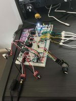
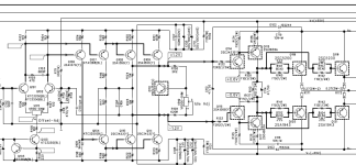
So I recently bought this Reference 404s amp really cheap. After receiving the amp I tested it and found that the 3 and 4 channel made a loud humming noise so I decided to open it up to see if there was an issue that I could spot on visual inspection and I found that the soldering on the input terminals was damaged. I fixed that but to no avail. The humming soundn was still there. No is maybe a good moment to tell you that I have no (very, very little) knowledge on electronics but always eager to learn something and having lots of time at the moment I decided to dive in. Watching youtube video's, bought a book on electronics, a cheap chinese handheld oscilloscope and component tester, trying to read shematics etc. Unfortinately I might have blown the amp up on one of the first steps with power connected to the board by pulling the board over something metal on my desk (I know pretty stupid!). So that's where I am now. I will list here what I've done so far and hope to get some new directions from you on what to do next.
Shematics are also below.
So, the amp doesn't power up anymore. The red led doesn't come on.
On visual inspection nothing is burned and transistors don't look damaged.
Measuring all the transistors on the board they seem all fine.
The transformer (T11 on the schematics) is (and was when I opened the amp) covered in solder on the bottom and the isolation is slightly damaged (see photo).
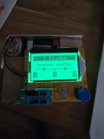
D20 and D7 "two diodes" seemed to short showing no resistance in which ever way I measured them however when I desoldered them and put them in my component tester it told me they're fine (see photo) so I put them back in.
Measuring the capacitors C37 and C36 in circuit the C36 capacitor measures 1000 uF and C37 doesn’t measure at all. Also there is no resistance between the + and – leads of the cap. Thinking the cap might be the problem I took it out but when I measured it out of the board there’s nothing wrong with it.
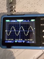
After putting it back in I decided to hook up the power supply again (12v max. 500mA). Nothing gets really hot fast but voltage drops to 6v on the power supply. Hooking up the oscilloscope gives me the image shown in the photo below.
That’s about as far as I’ve gotten so far. I hope to hear if what I wrote points into a certain direction. Thanks.
So I recently bought this Reference 404s amp really cheap. After receiving the amp I tested it and found that the 3 and 4 channel made a loud humming noise so I decided to open it up to see if there was an issue that I could spot on visual inspection and I found that the soldering on the input terminals was damaged. I fixed that but to no avail. The humming soundn was still there. No is maybe a good moment to tell you that I have no (very, very little) knowledge on electronics but always eager to learn something and having lots of time at the moment I decided to dive in. Watching youtube video's, bought a book on electronics, a cheap chinese handheld oscilloscope and component tester, trying to read shematics etc. Unfortinately I might have blown the amp up on one of the first steps with power connected to the board by pulling the board over something metal on my desk (I know pretty stupid!). So that's where I am now. I will list here what I've done so far and hope to get some new directions from you on what to do next.
Shematics are also below.
So, the amp doesn't power up anymore. The red led doesn't come on.
On visual inspection nothing is burned and transistors don't look damaged.
Measuring all the transistors on the board they seem all fine.
The transformer (T11 on the schematics) is (and was when I opened the amp) covered in solder on the bottom and the isolation is slightly damaged (see photo).
D20 and D7 "two diodes" seemed to short showing no resistance in which ever way I measured them however when I desoldered them and put them in my component tester it told me they're fine (see photo) so I put them back in.
Measuring the capacitors C37 and C36 in circuit the C36 capacitor measures 1000 uF and C37 doesn’t measure at all. Also there is no resistance between the + and – leads of the cap. Thinking the cap might be the problem I took it out but when I measured it out of the board there’s nothing wrong with it.
After putting it back in I decided to hook up the power supply again (12v max. 500mA). Nothing gets really hot fast but voltage drops to 6v on the power supply. Hooking up the oscilloscope gives me the image shown in the photo below.
That’s about as far as I’ve gotten so far. I hope to hear if what I wrote points into a certain direction. Thanks.
Attachments
Solavox 1970's speakers history/tweaks
- By Crimsontide
- Full Range
- 28 Replies
Hi
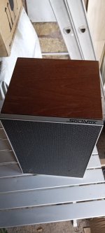
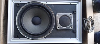
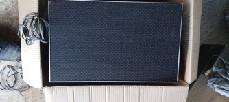
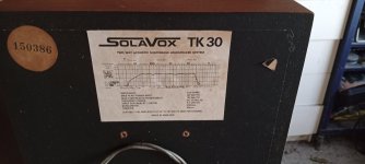
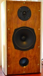
I recently acquired a pair of Solavox TK30 speakers and I'm wondering if anyone knows of the history or any tweaks that exist for this Speaker from a rare British Brand (Comet Electrical own-brand). The boxes are in excellent condition and are almost certainly the same as Leak 2020s as the overall dimensions are identical, the aluminium “picture frame” bezel on the front is the same as are the colour, round shape and typeface on the serial number labels. The speaker frets are the same material as the 2020s.
The only significant difference in the external appearance is that the drive units are stacked one above another, rather than having the tweeter offset to one side. The tweeter looks identical to that of the 2020, but there are no markings, and the bass/midrange is a paper cone unit with a single capacitor for a crossover, not the Leak sandwich type cone. The only other feature that might aid identification is a frequency response curve dated April 1976 on the back of one enclosure.
My theory is that, after Rank bought Leak, it was looking for ways to make the business more profitable and Leak had new designs on the drawing board that they could not afford to put in production because their existing range was not generating enough profit.
So when Comet came along enquiring about the supply of “mass market” hifi speakers, Rank saw a way to generate some funds without reducing the value of the Leak name, by using the Leak 20 series production facilities with component cost savings such as cheaper drive units and simpler crossovers which Wharfedale could provide as their speaker range went further down the price range.
I therefore think that the drive units are from Wharfedale (possibly from the Denton), and the combination of Leak enclosure with the Denton drive units should have resulted in a reasonable loudspeaker. I believe that the Solavox speakers were slated for muffled treble but I don’t recall any reviews.
The facts to support my hypothesis are:
1)The Leak company was acquired by the Rank Organization in 1969.
2) Rank had acquired Wharfdale Loudspeakers in 1958 prior to that it has acquired Bush Radio in 1945 and soon afterwards, in 1960, Murphy Radio. Rank therefore had a “stable” of companies with the ability to make audio electronics.
3) In the early 1970s Leak stopped making the 20 series speakers. These were superseded in about 1976 by the 30 series speakers e.g. 3030, with a “stepped baffle” front and different drive units. Leak also introduced a revised range of tuners and amplifiers.
4) From 1975 Comet Electricals started selling their own range of Hifi equipment, starting with a tuner-amplifier and a range of speakers. These were sold with the brand name "Solavox".
I would love to hear from anyone who either worked for the Rank Organisation or Comet who knows the true story of Solavox and Leak.
As an aside, I first became aware of the Solavox kit just after I had already set my sights on a pair of Goodmans Ministers which came from the Comet store in Dudley, along with either a Pioneer CTF-6161cassette deck and a Trio KD-1033 turntable. Whichever of those didn’t come from Dudley came from the Comet store in Selly Oak! Together with a pre-assembled Sinclair Project 80 amplifier from Laskeys in Corporation Street, they formed my first hifi.
Attachments
positive ground to negative ground conversion
- By Fossilshark
- Solid State
- 0 Replies
Hi all, I want to build this wah pedal, but I do not want to use a power converter to use it with my negative ground pedals. How would I go about converting this to negative ground?

Akai GX 210D hum in one channel
- By Atk1d
- Analogue Source
- 3 Replies
Hello Adrian, welcome back!
I would like to ask you a question.
I just picked up a well kept Akai GX 210D reel to reel.
Have all original items, box even.
Very clean. It came with service manual too.
Prior to sending tape thru it I plugged it in, hooked up the amp, power on.
There is a him seems like 60hrtz hum, when I toggle the tape selection switch the hum disappears.
Bad switch, bad cap in line or bad resistor?
I should mention the hum is only in the right channel.
Thanks for your time and input!
Cheers
Modding (rebiasing) a 2-stage phono pre
- By percy
- Analogue Source
- 60 Replies
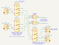
After reading a lot of positive reviews about this little known vintage radio shack phono pre I had to give it a try. Someone was selling it with modified/upgraded caps so I got one and I must say it was quite good. So I started looking into it see what other areas of improvement exist. One of the things that I wanted to evaluate (and where I need your help) is with the biasing and gain split between the two stages.
Question 1: The gain seems to be split in a very diverse amount between the two stages. If I am not wrong the first stage has several hundered (600?) of gain and the second stage is about 20 ? Does that seem right ? is it typical of such two stage phono pres to have the gain split like this? I felt a little more balanced gain split would help with noise and distortion performance. It should allow TR1 to be biased a bit away from the fringe limits. That brings me to my next question -
Question 2: TR1 voltages are quite low. Vc=1.82V, Vce=1.78v, Vb=0.61v, Vbc=1.15v and Vbe=0.51v.
I doubt its operating at its best. Couldnt find any meaningful datasheets for the transistor so going out on a limb here. Do you think it would help rebiasing TR1 (and thereby TR2 to keep total gain of the preamp same) to operate at somewhat higher voltages would help improve its performance in its operating range for such small signal voltages and currents ?
Question 3: What is 0.835V written in between TR1 and TR2 ? Is it Ve or Vce or what ?
Ikea Hacks
- By Bas Horneman
- Construction Tips
- 38 Replies
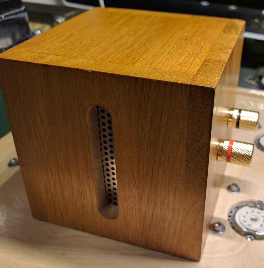
Pencil cups by Ikea turned into output transformer enclosures. (Small transformers only unfortunately)
Attachments


For Sale WHAMMY
For Sale Whammy with Muses01 op amp
See pics
Make me an offer or suggest a price ( I don't have a reference)


CONUS only
My desktop MAC died so I no longer need this unit - I want it to find good home
Thanks for looking
Bob
See pics
Make me an offer or suggest a price ( I don't have a reference)
CONUS only
My desktop MAC died so I no longer need this unit - I want it to find good home
Thanks for looking
Bob
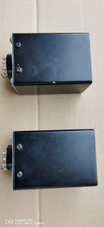
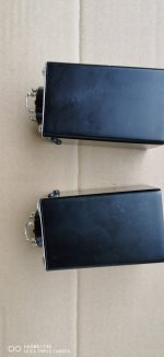
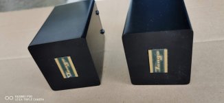
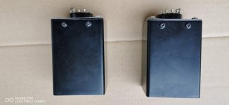
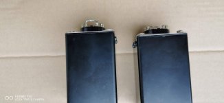
For Sale Tango MC cartridge step-up transformers MCT-999
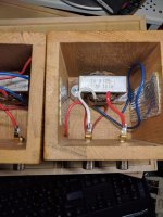
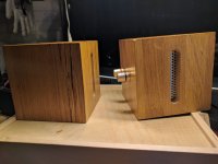
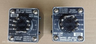
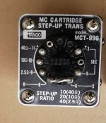
Extra Rare MC step up transformer manufactured by Hirata TANGO ( black color was special ordered ), this is one of the hardest to be found Tango transformer. IT can be used with all cartridge from DL-103 to SPU. I bought them in 1997 in Tokyo by Goko Trading a Distributor for Hirata / Tango. The MCT999 was made for MC cartridges and MM cartridges. Primary Impedance Step Up : Possibility to adjust the cartridge impedance to 2.5 / 10 / 40 ohm and bypass. Frequency Response: 10Hz - 50kHz (-1 dB) Max Output: 1V r.m.s . Dimensions: 50 x 56 x 65H mm Weight: 360gr. Both in good condition with light scratches. Worldwide shipping with additional Insurance. If you searching for other Hirata Tango Transformers, let me know.
The prices do not include PayPal and shipping costs. Shipping from Germany and with additional Insurance only by DHL. PayPal is accepted, the buyer pays the additional 5% PayPal fees. Outside the EU it may vary by country. If you are interested send me a PM.
Offers are welcome!
The prices do not include PayPal and shipping costs. Shipping from Germany and with additional Insurance only by DHL. PayPal is accepted, the buyer pays the additional 5% PayPal fees. Outside the EU it may vary by country. If you are interested send me a PM.
Offers are welcome!
Attachments
-
 TANGO MCT999 (1).jpg283.3 KB · Views: 369
 -
 TANGO MCT999 (3).jpg379.5 KB · Views: 345
 -
 TANGO MCT999 (4).jpg191.5 KB · Views: 287
 -
 TANGO MCT999 (5).jpg157.9 KB · Views: 232
 -
 TANGO MCT999 (6).jpg135.9 KB · Views: 234
 -
 TANGO MCT999 (7).jpg137.4 KB · Views: 235
 -
 TANGO MCT999 (8).jpg169.9 KB · Views: 224
 -
 TANGO MCT999 (9).jpg129.8 KB · Views: 251
Virtual Center Tap Grounding
- By joneci
- Tubes / Valves
- 3 Replies
Quick question as virtual center taps are new to me…
I would like to provide a CT for the 6.3V heater for the driver tubes on my amp. The easiest place to add these is at the power transformer. My question is, can I ground the two 6.3V CT resistors directly to the center tap lug of the high voltage secondary on the PT?
It seems like this would be fine as the HV CT goes directly to ground; however, this is new to me and would love to hear your thoughts!
Synergy Horn with Heil AMT
Hi all,
I've been lurking for a while... and have thinking about what to do with my Great Heil AMTs that I got a year ago when they went half price with free shipping..
Originally I bought them to make speakers based on Xrk's Kazba but then saw Xrk's post on his Synergy Horn using the AMT in lieu of a compression driver.
My Xki's are *still* away for painting but when I did listen to them prior to painting I absolutely loved them, and so trust Xrk if he says something sounds good. Well he said that the AMT horn was among the best speakers he has ever heard!
So I have read up on the theory of them and how to build them and have played around with the spreadsheet by Bill Waslo (thanks Bill!).
But I have some questions about this process I would love to get some help with.
1) With the ESS Heil AMT, I have read that it has a very small vertical dispersion. Is there any point in going for 40 degrees of vertical dispersion or more? Is even less worth pursuing? The smaller the vertical dispersion of the horn, the shorter it can be made.
2) Likewise with the horizontal, I am currently aiming for 90 degrees, as any less than that makes the horns too big (at the moment with 90 degrees and 390Hz pattern control it is 60cm (23.6 inches) wide, which is as large as I would like in my living room).
Question is, is 90 degrees a good value to go with? My seating position will be about 2-3m from the speakers position. 90 degrees horizontal dispersion *seems* good to me from my seating position, but any thoughts would be appreciated.
3) I am aiming for 390Hz as my bottom horizontal pattern control value, but can anyone advise on the choice for this value? The default the spreadsheet comes with is 385Hz and the manual mentions that something in the range of 200-500 will suit most rooms but any extra information would be appreciated.
4) I believe I have found the woofer to match with the AMT: The Peerless SDS-160F25PR01 Peerless by Tymphany SDS-160F25PR01-08 6-1/2" Paper Cone Woofer Speaker
Sealed it should go from 70Hz to 3000Hz nicely. Ported from 33Hz.
Therein lies my question. I was originally planning on doing a 3-way - a 2-way synergy horn with a bass horn on the bottom, like Xrk's project.
That would mean 1 or 2 of these woofers + the Heil AMT in the synergy horn and then building a ~30Hz bass horn to sit underneath and do from ~30-100Hz.
But then I thought, this woofer ported goes down to 33Hz. Why not have a ported synergy horn that has 1 or 2 of these woofers in it and have an all-in-one synergy horn? I did some modeling in WinISD of the woofer and what volume is ideal and how I would vent it, and settled on 60L box tuned for 33Hz. 2 ports, 6.8cm diameter @ 9.28cm long each. 1st port resonance will be at 1852Hz, and max air velocity will be 5.2m/s @ 33Hz.
Firstly, is that a good idea or a terrible one?
Secondly, do you think 1 of these drivers is enough? Or should I get two each for the left and right channels? I don't plan on listening at ear splitting volumes, but I also don't want to underbuild as well. If I get two for each horn then I will need 100L cabinets as well which is a bit larger.
Any thoughts will be welcome.
Thanks to anyone who shares their thoughts to help me.
Criteria for choosing the right L and C in second-order crossover
According to the resonance formula; Fc = 1/(2 x pi x sqrt(LC)), it’s clear that Fc depends on the product of L and C. So there are many combinations that yield the same product values. For example, 3.5mH and 100uF gives Fc of 270Hz, so does 4.0mH and 87uF combo.
However, assume Re of the driver is 4 Ohms in both combos, the difference is on Q of the filter. Consequently,
1) What is the criteria for choosing L, or C, for the initial step? That is, assume Re = (ideal) 4.0 Ohms, L = 3.5mH or 4.0mH for the first component.
2) With Re = 4.0 Ohms, the 3.5mH and 100uF produces Q = 0.676, while 4.0mH and 87uF produces Q = 0.590. Which one is more preferred?
I know the process should involve measurement, however, I also believe the calculation could be performed before measurement (for some people) as well.
Using a DAW (Digital Audio Workstation) as DSP?
- By Horneydude
- PC Based
- 15 Replies
Hello, lately I am tinkering with CamillaDSP on Linux Mint (latest kernel) and a Focusrite 8i6 usb interface, the software is very nice and I got it to run, but I do have problems to solve with Alsa and Pulseaudio, and the troubleshooting is very timeconsuming. So I was thinking if it would be possible to run and configure a DAW like ProTools (that I have installed) with plugins and a multichannel usb card? The entry ProTools is also free. I use ProTools for my homestudio and it works multichannel out of the box (Windows only, that is the sad part) and routing, eq, delay etc. should be no problem. Low latency, as much tracks (channels) as you want and your computer can handle. If you f.e. have a 4 channel output card you can route 4 tracks to those outputs. Inputs are also no problem, as the software is designed to actually record something and monitor the process of recording, and send audio to busses or other channels. So I do not see specific hurdles to configure a DAW as a DSP for use as a DSP crossover for an active speaker system. With a plethora of plugins available, you can create anything that is required. Any thoughts, someone already doing this? I am certainly planning to give it a try.
TO3 footprint
- By lampisterio
- Electronic Design
- 5 Replies
Greetings to all of you.
I would like to rebuild an amplifier with Hitachi TO3 mosfets, with this orientation (35°) on the bracket. I use Kikad but I can't find the correct footprint, where can I find it? Designing it from scratch is difficult for me.
Thank you

I would like to rebuild an amplifier with Hitachi TO3 mosfets, with this orientation (35°) on the bracket. I use Kikad but I can't find the correct footprint, where can I find it? Designing it from scratch is difficult for me.
Thank you
Please help with homemade C core inductor for CLC amp supply
- By valtra103
- Power Supplies
- 3 Replies
Hello.
I am trying to make ironcore inductors from some old transformers. Some things are not clear to me:
Please check photos, where I marked areas of interest.
Photo 01:
 1. Which parts can touch? (see picture). Can any off B's touch Frame A?
2. How many insulated gaps in core? One or two? Insulation between B3-B4 and B1-B2? or one insulated, one just glued?
3. If only one core gap needs is insulated, then I need make sure that another one is conductive? So i need to be careful so glue doesn't insulate that junction by accident?
__________________________________________________________________________________________________________________________________________________________________________________
Photo 02:

4. Can I build just one coil former, and wind all wire on it like shown in picture? Or do I need to wind two like original transformer, and connect in series?
5. If one coil is fine, D or H gap should be insulated? Or both?
6. Is there rough rule of thumb how much inductance I could get, knowing that this was normal 220V transformer. I probably should try winding some windings with random wire, and measuring inductance, since wire thickness should not make big difference in calculating?
I am trying to make ironcore inductors from some old transformers. Some things are not clear to me:
Please check photos, where I marked areas of interest.
Photo 01:
2. How many insulated gaps in core? One or two? Insulation between B3-B4 and B1-B2? or one insulated, one just glued?
3. If only one core gap needs is insulated, then I need make sure that another one is conductive? So i need to be careful so glue doesn't insulate that junction by accident?
__________________________________________________________________________________________________________________________________________________________________________________
Photo 02:
4. Can I build just one coil former, and wind all wire on it like shown in picture? Or do I need to wind two like original transformer, and connect in series?
5. If one coil is fine, D or H gap should be insulated? Or both?
6. Is there rough rule of thumb how much inductance I could get, knowing that this was normal 220V transformer. I probably should try winding some windings with random wire, and measuring inductance, since wire thickness should not make big difference in calculating?
Fixing a Wadia 3200 CDM1 broken transport
- By dazaa
- Digital Source
- 10 Replies
I'm trying to rescue this Wadia 3200 that has been butchered by someone in the past. I believe the original fault was not reading discs, likely down to caps on the CDM1 mechanism. Problem is whoever had it before tried to open it and in doing so has broken one of the white plastic guides on the tray, does anyone know where I can find this part?
1.5 or 2 inch round over for wide baffle?
- By SpinMonster
- Full Range
- 9 Replies
I am going to round over the edges of an 18.75 inch wide baffle housing a Seos 15 and 15 inch woofer. Is a 1.5 inch round over sufficient? I’m concerned about the thickness at the corners if I go 2 inch. I was planning on a 1.5 inch thick baffle and 1.25 sides with a corner strip inside to make it thicker where I’m removing material. Moving to a 2 inch I would need 19.75” wide baffle.
Is there any benefit with 2 inch over 1.5? Can it hurt things?
The speaker is actively crossed.
I would prefer as narrow as possible for the baffle.
I require a round over for the grill type but can get away with 1 inch for that if there is no other benefit with 1.5 or 2 inch
Is there any benefit with 2 inch over 1.5? Can it hurt things?
The speaker is actively crossed.
I would prefer as narrow as possible for the baffle.
I require a round over for the grill type but can get away with 1 inch for that if there is no other benefit with 1.5 or 2 inch
Neurochrome Modulus-286: 65W (8Ω); 125W (4Ω) @ <-120dB THD Composite Amplifier Module
- By tomchr
- Vendor's Bazaar
- 241 Replies
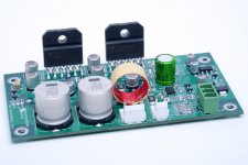
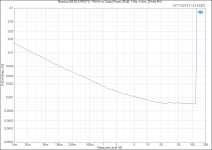
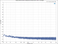
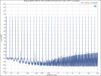
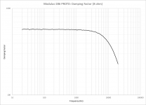
Neurochrome Modulus-286: 65W (8Ω); 125W (4Ω) @ <-120dB THD Composite Amplifier Module
Key features:
Note that attached picture and measurements are of the prototype. I will follow up with a more comprehensive set of measurements once the production version is in.
The production version will be Neurochrome Blue and professionally assembled in Calgary on a gold-plated PCB made in Ontario, Canada. The finished module will include aluminum mounting hardware (also made in Canada), which allows the module to be bolted directly onto a heat sink. This mounting method greatly simplifies the mechanical work for the the DIYer (only three holes needed with ±0.5 mm precision in their location).
Fully assembled modules are in stock and available for purchase here: Modulus-286: 125W power amplifier achieving -120dB (0.0001%) THD – Neurochrome
Enjoy.
Tom
Key features:
- Mono construction.
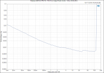
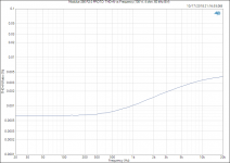
- 65/125 W into 8/4 Ω, respectively @ THD < -120 dBc.
- Tested for stability with reactive loads up to 1.0 µF || 8 Ω.
- Multi-tone IMD residual: < -100 dBV.
- Damping factor: >560 @ 1 kHz; >225 @ 20 kHz (8 Ω).
- Integrated noise (20 Hz - 20 kHz): 17 µV (A-weighted); 22 µV (unweighted) @ 20 dB gain.
- Integrated noise (20 Hz - 20 kHz): 27 µV (A-weighted); 32 µV (unweighted) @ 26 dB gain.
- Balanced input (can be connected to unbalanced sources as well).
- Default gain: 26 dB for ease of use with other HiFi components. 20 dB available upon request. Higher gain possible by a simple resistor swap.
- Four-layer PCB, fully optimized for the highest performance.
- Designed, manufactured, and assembled in Canada. All components sourced from reputable distributors (Mouser, Digikey, et al.)
- Available for pre-order within the next few days with a significant early adopter discount. Expected in stock by the end of November, 2018, at which point the into sale will end.
Note that attached picture and measurements are of the prototype. I will follow up with a more comprehensive set of measurements once the production version is in.
The production version will be Neurochrome Blue and professionally assembled in Calgary on a gold-plated PCB made in Ontario, Canada. The finished module will include aluminum mounting hardware (also made in Canada), which allows the module to be bolted directly onto a heat sink. This mounting method greatly simplifies the mechanical work for the the DIYer (only three holes needed with ±0.5 mm precision in their location).
Fully assembled modules are in stock and available for purchase here: Modulus-286: 125W power amplifier achieving -120dB (0.0001%) THD – Neurochrome
Enjoy.
Tom
Attachments
-
 MOD286_PROTO.jpg306.4 KB · Views: 2,821
 -
 Modulus-286 R2.0 PROTO_ THD+N vs Output Power (8 ohm, 1 kHz, 20 kHz BW).png50.8 KB · Views: 2,628
 -
 Modulus-286 R2.0 PROTO_ THD+N vs Output Power (4 ohm, 1 kHz, 20 kHz BW).PNG46.7 KB · Views: 2,603
 -
 Modulus-286 R2.0 PROTO_ THD+N vs Frequency (50 W, 8 ohm, 60 kHz BW).PNG35 KB · Views: 2,560
 -
 Modulus-286 R2.0 PROTO_ THD+N vs Frequency (100 W, 4 ohm, 60 kHz BW).PNG36 KB · Views: 2,564
 -
 Modulus-286 R2.0 PROTO_ THD+N vs Output Power (26 dB, 1 kHz, 8 ohm, 20 kHz BW).PNG51.1 KB · Views: 397
 -
 Modulus-286 R2.0 PROTO_ THD+N vs Output Power (26 dB, 1 kHz, 4 ohm, 20 kHz BW).PNG47 KB · Views: 475
 -
 Modulus-286 R2.0 PROTO_ Residual Hum & Noise (8 ohm, 1M FFT, 8 averages).PNG50.9 KB · Views: 481
 -
 Modulus-286 R2.0 PROTO_ Muli-Tone IMD (AP 32-tone, 50 W, 8 ohm, 1M FFT, 8 averages).png68.9 KB · Views: 494
 -
 Modulus-286_R2p0_DampingFactor.png61.8 KB · Views: 625
Jhofland’s Diamond Buffer
Jhofland designed a nifty little diamond buffer that I got to try out for the past week. It works superbly and can drive 32ohm headphones with ease. It perfectly mates with a BTSB or a HyperSET hybrid tube buffer as the voltage gain stage. Jhofland had graciously allowed me to use his design and make it available as a preassembled ready to run run (RTR) board.
More info on HyperSET here:
https://www.diyaudio.com/community/threads/btsb-with-tube-buffer-hyperset-gb.396848/
Diamond buffer schematic:

PCBA render:

Prototype under testing:


I’ll let Jhofland provide the particulars of the circuit but I do know it is Class AB and uses an LED to set the current sources. It’s an all BJT design and can take +/-12v to +/-20v (tested). Probably can go higher even.
More info on HyperSET here:
https://www.diyaudio.com/community/threads/btsb-with-tube-buffer-hyperset-gb.396848/
Diamond buffer schematic:
PCBA render:
Prototype under testing:
I’ll let Jhofland provide the particulars of the circuit but I do know it is Class AB and uses an LED to set the current sources. It’s an all BJT design and can take +/-12v to +/-20v (tested). Probably can go higher even.
Hello! Here I am ...
- By LabGuy
- Introductions
- 4 Replies
Hello to all members.
I've been in the electronics field for almost 50 years, working in Hi-Fi and TV shops, industrial electronics and also teaching electronics. I now enjoy designing tube amplifiers and repairing Hi-Fi equipment. I live in Canada.
I've been in the electronics field for almost 50 years, working in Hi-Fi and TV shops, industrial electronics and also teaching electronics. I now enjoy designing tube amplifiers and repairing Hi-Fi equipment. I live in Canada.
Looking for proper subwoofer for EDM Wubzzz. Must have balanced output/input
- By Ler
- Introductions
- 1 Replies
I have been DJing since I was 16, I am now 27. I love listening to EDM music. I love the loud bass it produces. Bass music primarily. House music, dubstep, riddim sometimes. I also love rap, rock, orchestras music.
I have KRK Rokit 5s. Looking for something to pair it up with. Focusrite Scarlet solo the newest version I think so it has balanced output. Thing is, I used to have and SVS subwoofer the 10 inch one but it didnt have balanced outputs, so im looking for one specifically with balanced outputs to match with my scarlet solo and my KRKs.
Main Questions:
1. Should I just get the KRK subwoofer to match with the KRK studio monitors, or is it worth finding another sub to get more punch out of the bass? is there a better bang for my buck?
2. What subwoofer do you personally have that you love? Do you listen to EDM music? Looking for something dope, I just found this site.
3. Thats really it. I have a scarlet solo into my computer that used to go into my subwoofer then into my studio monitors, but now i need a balanced subwoofer.
Hope this was ok to post. I see a lot of ppl building their own speakers and im not there yet, but would be down to learn, I like building computers. Thank you
Intro, Hello to all I am a new member here. I have multiple hobbies and interests one passion has always been Audio
- By markomarko33
- Introductions
- 1 Replies
Hi my name is marko, my interest has always been for over 40 years the passion for audio and building anything that is esoteric and simple for audio. I also built 30 years ago a preamp with the 211 valves ispratomi from Sakuma. Happy DIY to all.
Hi I'm new here
- By Wellco
- Introductions
- 1 Replies
I'm trying to build a whole home audio system based on my existing speakers that are from a time before 'Smart'. I have little knowledge of electronics, but have a 'can do' approach. I am handy enough and soldering components and wires is not a problem. Other than that I like cycling, photography.
Never Too Late
- By sarakisof
- Introductions
- 1 Replies
Ages of reading & silent following.
I'm not that super hi-fi clean guy, coming from a production rehearsal & guitar tube amp background climate. Probably more close to old dirty repairman / player side than listener, but I owe a lot to this place.
Old member of other audio, valve amp, diy places out there.
I know there are some well known old dogs here, who have helped me through other forums in the past. Will always be honoured to them. They know who they're.
Salute everyone. 🙏
Much love & greetings from Greece.
Looking for the schematic diagram for a ds 18 candy 5xb amp
- By legion2710
- Car Audio
- 1 Replies
I need to know the value of some diodes on the sub woofer stage ..anyone have a diagram .?
What might be ballpark L&C to make a 1K2 lowpass to get some "boost" ?
I have a little horn loaded with a Tymphany 10" speaker which has to mate with a horn and B&C DE25. The Tympnayh could use a bit more output in the 1K or so region. (will look at hornresp)
It will be driven with a TPA3255


It will be driven with a TPA3255
Attachments
6BM8 "tiny tube amp" build + Video Series
- By stephe
- Tubes / Valves
- 106 Replies
I decided to make a video series of my next project, a small 6BM8 SE UL scratch built amp that is perfect for a beginner or anyone looking for a fun project to build. You should be able to get all the parts new for under $300, it's a simple design and from what I have read, these are great sounding tubes.
I plan to post a final schematic and a BOM once I finish the amp and get everything sorted out. I am explaining in fine detail my thought process, tips on chassis fab work etc. so anyone with basic tools and are good with their hands should be able to build one. I also plan to show how to test it on a scope and the process I use for tweaking different things to get the best sound out of it.
I have warned folks, if you think you might want to build this with the 10W 5K Edcor UL output transformers I am using, you might want to order them now. It's taking 8-10 weeks to get these. The rest of the parts are pretty easy to find.
Anyway, I wanted to share it here. I'm about half way done, all the fab work is finished and the layout decided on, just waiting on a few parts to finish wiring it all up. Hope you enjoy following along as I build it.
6BM8 DIY Stereo Tube Amplifier Series - YouTube
Attachments
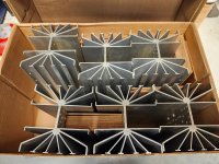
For Sale Large vertical Heasinks (6) for Krell or Mark Levinson Class-A style amps
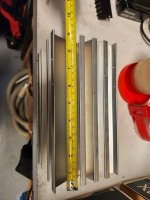
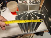
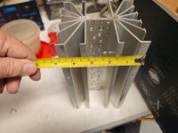
FS, Large vertical Heasinks (6) for Krell or Mark Levinson Class-A style amps, used with TO/3 drilling. Great Heasinks for your Class-A project, see pictures for details.
Each heatsink weights 1.4kG. Can also accept TO-220 or TO-264 parts with a little work, that's DIY after all. Was aving them for a Krell KSA-50 project that I have to let go.
Asking 50U$ + shipping.
Payment with Paypal (3.5% fee) or EMT bank transfer within Canada
Thanks for looking
SB
Each heatsink weights 1.4kG. Can also accept TO-220 or TO-264 parts with a little work, that's DIY after all. Was aving them for a Krell KSA-50 project that I have to let go.
Asking 50U$ + shipping.
Payment with Paypal (3.5% fee) or EMT bank transfer within Canada
Thanks for looking
SB
Attachments
For Sale Vacuum State Electronics RTP3D, upgraded from an original RTP3C kit
- By mattattnet
- Swap Meet
- 9 Replies
SOLD
Asking $3800 $2000 plus USA shipping. Will only ship to USA
I will start with a caveat. I believe the person purchasing this preamplifier needs to have the ability and interest to SAFELY work within a tube audio product with 360vdc power as checking the output of the Superregs and power supplies is a likely need. I consider this preamplifier to be like a high performance car, in that familiarity and upkeep are a necessary part of ownership. This is not a typical plug and play audio component.
When last available the kit form of this preamp was well north of $10,000, and the factory built unit was $25,000.
Vacuum State RTP3D, which started life as a RTP3C kit I purchased from Allen back in the day. This is a differential line stage and MM/MC phono stage preamplifier. I later purchased the RTP3D update CD and buffer board information from VacuumState, built the choke loaded power supply in 2020, got it in a newer, less ratty chassis then the 3C power supply came in, and at the beginning of 2022 rebuilt the signal chassis with some silver wire, some copper wire, all new resistors, all new matched phono board components, SM2210, and a change of regulators for the -24 volt supplies to very quiet and very stable LDO regulators using the AMB.com boards. All new components except the film caps were put in the SuperReg boards also. I designed and installed a new signal chassis back plate with only rca (audio note silver plated) and XLR (neutrik) jacks. The unit has Elna source switches and DACT stepped mono attenuators.
The unit has seen little use since then as I got out of vinyl just after that. About 100 hours maximum.
Gain of the preamplifier section can be changed from about 40db to 0db by soldering in a couple resistors, and the gain of the phono sections can be changed in a similar fashion. Presently gain is set at 10dB for the line stage and 45 dB for the phono section.
Included tubes are eastern euro PCC88 tubes, the amp filament regulators are set to run at 300mA each for these series heaters. The filament regulators are set for 6922/ECC88/PCC88 type tubes, not 6DJ8 that have a different filament current need.
I just did some cursory testing of the unit again, and all is well. I was going to make new superreg boards, but never got around to it. The superregs run HOT, and I kept the shunt current to about 10mA to put less heat into the shunt components, and to my failing ears, sounds no different than the spec’d 15 mA shunt current.
The sale includes the pictured power supply and signal chassis, the original RTP3C, RTP3D, and buffer board information / pdfs on CDs, some extra silver wire if you wish to go that route, and I will send you some pdf links to updates on the RTP3D schematics that correct some inconsistencies in the VS documentation. I will include a printout of the Superreg documentation…it is marked up. I will NOT sell the build info from VaccumState separate from the preamp. It is their IP.
Weight of the signal chassis and power supply is over 40lbs combined.
USA shipping and sale only. I plan to package as carefully as possible with rigid foam around all sides of each component.
Shipping would be in a 20 x 20 x 12 box, about 50 pounds.
Contact me here if you have additional questions or want some more specific information.
Do I need capacitors in a passive audio switching circuit?
- By zodiux
- Electronic Design
- 6 Replies
Hi,
I'm trying to build a 3 channel audio switcher. 3x 3.5mm inputs and 2x 3.5mm outputs one for headpones and one for speakers. I'm using DPDT relays to switch channels. I've added 2 digital potentiometers for volume control, which is controlled by a Pico and Rotary encoder. Because I'm using DC components (DigiPots and Relays), do I need to add blocking capacitors before each of those components?
Another forum mentioned this: "If you use an electrolytic, I recommend a bi-polar type between 10uf and 22uf." (https://modwiggler.com/forum/viewtopic.php?t=171691)
So I was planning on whacking a few 10uf bipolar electrolytic caps in the circuit, but I'm not sure if this is even necessary...
I've attached my current schematic (not including all the digital control circuits, just components directly in the audio path).
Any help would be greatly appreciated! 😀
Attachments

Hi, I'm new here and know very little about electronics!
- By zodiux
- Introductions
- 1 Replies
Hi, I'm working on a small 3 channel audio switcher for the devices at my desk, I'm new to electronics and I'm almost certain theres things I'm missing when it comes to my current design/schematic. Looking forward to being educated and told my design is wrong lol. 😛
6S41S Single-Ended Amplifier
- By wrenchone
- Tubes / Valves
- 8 Replies
I'm contemplating doing a single-ended amplifier using the 6S41S triode, perhaps with a depletion-mode mosfet front end. I'm thinking of using the Toroidy 600 ohm primary toroidal single-ended iron for the output, and a discrete shunt regulator to bias the cathode (damped/bypassed by a capacitor of suitable voltage rating). I would run the front stage off the output of a Plitron medical isolation transformer I have a couple of, and the 200V for the output stage would be generated with a discrete self-driven buck regulator with suitable filtering. I need to rummage around and actually find my 6S41S stash, and I think I have a couple of suitable sockets (the tube is a little weird, and takes a strange 7-pin socket).
Tinsel lead repair - advice sought
I have a driver that needs fixed, an Usher midwoofer from an S520. One of the tinsel leads has come adrift from the voice coil lead-out wire. Here's a picture:

The voice coil lead-out wire is glued to the cone, which is clear plastic of some sort. I plan to use a scalpel to scrape the lead-out wire to expose a little more copper, and also to lift the end of it clear of the cone, before attempting to solder the tinsel lead back onto it.
The tinsel lead has a big blob of yellowish glue on the end, which was supposed to hold it in place. That'll need to be removed, and when I've resoldered the wires together, I'll need to glue the joint down onto the cone with a fresh blob.
Have I got all that correct? Any advice? What type of glue would be best for regluing the joint to the cone?
Adding a tweeter control to an existing Crossover
I have this idea of adding either heavy duty pot to a crossover for the adjustment of a tweeter in a crossover or at least a switch that would adjust tweeter level. The tweeter is 10 DB more efficient than the woofer so I am betting that there could be some latitude here. As it sits now, the tweeter is padded down by 10 DB. It is a 2-way crossover with a 2nd order Butterworth slope at 2.5 Khz. The woofer is a Mark Audio 12PW used in a loaded horn design, and the tweeter is a Scan Speak horn loaded tweeter. I will have to look at the model number. I bought it from Madisound for about $42 ea.
I would actually like to tip up the tweeter level just because it might help me and my old ears but then maybe a bad idea. You guys will certainly have valuable advice. Thanks.
I would actually like to tip up the tweeter level just because it might help me and my old ears but then maybe a bad idea. You guys will certainly have valuable advice. Thanks.
Converting obsolete AV receiver to powerful class A amp?
- By jeannot60
- Solid State
- 33 Replies
Top of the line yesterday receivers (without, or with broken hdmi inputs) are going to the recycling every day. This is really sad, given their huge, no longer produced power supplies, and their massive heatsinks. So much potential. I just cannot watch these being recycled or trashed. Just unethical waste. Example:

So I started buying them left and right, for 1/100 of their original cost. Been gutting them and putting cheap chinese amp PCB in there with impressive results.
But then I started thinking: These also came in some cases with elaborate amps, and real, first quality output transistors that simple cannot be bought on the chinese web sites. Then came the crazy ideeyer of using all those resources to build class A amplifiers? Some of them have state of the art input stages in their amplifier, even resembling the well known "blameless" topology. Their ouput transistors are guaranteed not to be chinese knock-offs. And their heatsinks are huge.
I want to try to convert one these amps to class A.
Shields down please and no "it can't be done", "they're not designed for that", etc... Hope are not made to be shattered.
Case in point: In the following class AB schematic, the input stages are perfectly fine.
 I am seeking advice on how to take away and rewire one half of the output stages to change the (probably positive) side to a current source, possibly involving redesigning what is inside the red circle.
Please, let us waste anyone's time with how it cannot be done. I am seeking amplifier design advice on how to go about it with the least chances of failures.
And yes, I am aware of the voltage, current and power dissipitations issues. I will consider them off-topic. I am seeking help about the topology of the circuit, nothing else.
Thank you!
So I started buying them left and right, for 1/100 of their original cost. Been gutting them and putting cheap chinese amp PCB in there with impressive results.
But then I started thinking: These also came in some cases with elaborate amps, and real, first quality output transistors that simple cannot be bought on the chinese web sites. Then came the crazy ideeyer of using all those resources to build class A amplifiers? Some of them have state of the art input stages in their amplifier, even resembling the well known "blameless" topology. Their ouput transistors are guaranteed not to be chinese knock-offs. And their heatsinks are huge.
I want to try to convert one these amps to class A.
Shields down please and no "it can't be done", "they're not designed for that", etc... Hope are not made to be shattered.
Case in point: In the following class AB schematic, the input stages are perfectly fine.
Please, let us waste anyone's time with how it cannot be done. I am seeking amplifier design advice on how to go about it with the least chances of failures.
And yes, I am aware of the voltage, current and power dissipitations issues. I will consider them off-topic. I am seeking help about the topology of the circuit, nothing else.
Thank you!
Attachments

Power stage impedance
Newbie question I guess, but I searched the forum and found no fitting answer.
Suppose I want to control the behavior of the power input stage used with a class D amplifier (in my specific case I'm planning to use a MA12070p).
What can I assume the impedance load will be?
Knowing that, I could dimension a R-C network for, for example, set up a soft start.
One could argue that since you want most of the power to go to the speakers, you can assume that this is the main load. However, there is also a charge pump in the middle, among other amenities, and it all seems beyond my current understanding of (this kind of) electronics.
A good budget combo
Here's a simple 2 way I just put together out of parts from my stash. A 2 way, Woofer is Wavecor WF160WA02, a well behaved good sounding driver, NLA, but its Round Frame version the WF168WA01 (identical specs) is available in Aus for $75. Tweeter is SB21SDC-C000-4, (~AUD60, I bought these a few years ago, so paid a bit less) nice dispersion chracteristics.
Simple xover at ~ 1750Hz, .27mH on the woofer to smooth out its top end, 12uf & .68mH 2nd order on the tweeter. Box repurposed from a previous project, 29L tuned to the mid 40s gives a slight bass lift. No BSC but doesn't seem to need it, if I need more lows I can always turn on my dedicated woofer boxes.
Simple xover at ~ 1750Hz, .27mH on the woofer to smooth out its top end, 12uf & .68mH 2nd order on the tweeter. Box repurposed from a previous project, 29L tuned to the mid 40s gives a slight bass lift. No BSC but doesn't seem to need it, if I need more lows I can always turn on my dedicated woofer boxes.
Attachments
Subwoofer cabinet design construction and testing
- By ginetto61
- Subwoofers
- 245 Replies
Hi ! i am here after coming to a very important conclusion
The subwoofer duty is the most challenging application for a cabinet (too trivial ? 😉)
Let me elaborate a little first
Above a certain frequency the vibrations level is so low that taming them is not a big issue
I would fix the cut at about 200Hz more or less
For this reason my ideal speaker has the bass box separated by the other drivers
The range up to 200Hz is very well within the limits of any kind of sub even the biggest ones And that is what i would like to do in the future
A satellite dealing with the range from 200Hz up above a sub with some kind of mechanical decoupling
This said i would like to hear what kind of test do you perform on your subwoofer cabinets
In particular my main interest is to understand what kind of measurements could provide the most reliable information about the quality of the design and construction of a cabinet for a subwoofer
I mean you can brace and add mass to the cabinet
But how do you know when the cabinet is well done ?
Then i would like to suggest a very weird test to get an idea of the vibrations of a cabinet side
Just stick with some biadesive tape a small piece of mirror on the side and direct a laser beam on it from an angle
The movements of the mirrored point will provide a measure of the vibration of the cabinet side
In the ideal case the point should stay steady without any kind of oscillations
Of course the front baffle is the most critical side As always for speakers in general
Thank you very much indeed
Kind regards, gino
Aleph J power supply
- By yarozebob
- The diyAudio Store
- 2 Replies
Hi i am a newbie amp builder and i have 3 questions. can i use the nelson's bipolar power supply for and aleph j zen mod? can i use the antek AS-3218 with it? and how in the world do i wire it up?
Seeking advice for a mini 3-way speaker (Woofers!!)
Hello,
I acquired a pair BlieSMa M74S-6 for a great price. The seller was upgrading their MUM-8 to the beryllium version of the dome midrange. I got very lucky!!
Let's pair the M74S-6 with the T25S-6 and plan on a passive crossover design to start. I don't want to go active quite yet.
What I would love help with is finding a 5" (or possibly a 6" or even dual 4") driver to build a compact 3-way?
From HiFiCompass' study of the M74 product line, I am assuming the high-pass will have to be near 500Hz.
I would like to keep the enclosure for the driver under 0.35 cu. ft. (10 liters).
Not sure I can ask for much in the way of sensitivity here. Getting close to 90db 2.83v/1m would be the dream.
Shooting for an F3 in the mid 60Hz range and F6 in the 50Hz range, if possible.
I am down to mounting the BlieSMa drivers on a flat panel akin to the LX521.4 or building them into an enclosure like the Barefoot Sound Footprint 01 where the woofers are locating on the side of the cabinet.
Here are a couple of options I have found.
Anarchy-554
SB Acoustics SB15NRX2C30-4
Currently, the mini 2-ways I am using contain a T25A-6 along with a Purifi PTT4.0X04-NAC-03 and utilizing a 6" Purifi PR. Loving these speakers!
They are flanked by a small subwoofer.
Fun thoughts on this one?!
VituixCAD - Where to download FRD and ZMA?
- By lineup
- Software Tools
- 3 Replies
Dayton Audio has data for download to most of their Drivers.
But where is some good site for downloading other Drivers data?
What is needed is FRD and ZMA in VituixCAD.
But where is some good site for downloading other Drivers data?
What is needed is FRD and ZMA in VituixCAD.
WTB Kef T33 sp1191 Tweeters
- By TheFinisher
- Swap Meet
- 0 Replies
I have amassed some nice tweeters so I’m hoping someone else has too along with a pair of the above 😁
Who owns diyAudio?
- By mbrennwa
- Forum Problems & Feedback
- 2 Replies
This may seem like a simple question, but I could not find the answer: Who owns and operates diyAudio?
I am sure this information is available somewhere, but I was not smart enough to find it.
I am sure this information is available somewhere, but I was not smart enough to find it.
For Sale Ryan D3 TDA1541 DAC
Fully built and tested Ryan's D3 TDA1541 dac on sale using high quality parts. I will include a Miro 1541 psu board if anyone wants to use that to power the D3. Too many dacs in my line-up so these need to make place for other builds. I am using a Aya 5 with the same TDA chip in my main setup as well as Soekris R2R dacs / AD1862 dac in my second setup.
More information about this dac here - https://www.diyaudio.com/community/threads/diy-tda1541a-pcb-d3.328060/
Asking $400 including psu board and free shipping within CONUS.


More information about this dac here - https://www.diyaudio.com/community/threads/diy-tda1541a-pcb-d3.328060/
Asking $400 including psu board and free shipping within CONUS.
This must be the place ...
- By Coltrane1013
- Introductions
- 1 Replies
Hello all! After many google searches for particular gear issues, one thing was consistent - people on DIYAudio were discussing (and solving) the issues and modifications that interest me. I work at a small used record/cd/tape shop that also sells vintage stereo gear: mostly Marantz, Pioneer, Klipsch, Technics, Sansui, Carver, etc. Receivers, integrated amps, separates, speakers, turntables. At home, I'm currently running a McIntosh C29 + MC2105 feeding a pair of Dahlquist DQ-20's. Mostly listen to records on my Technics SL-120mk2 with a Nagoaka MP-200 cart > Parks Audio Budgie tube phono stage. Streaming digital through a Wiim Mini > Schiit Audio Modius DAC. Always interested in reading discussions on gear, repairs and modifications. Looking forward to learning more and participating in the discussions. Thanks!
Introductions
- By Duncan2012
- Introductions
- 1 Replies
Hello everybody,
I'm new here on diyAudio forum. I am interested in DIY audio equipment.
Vlado
I'm new here on diyAudio forum. I am interested in DIY audio equipment.
Vlado
Hello! Thank you for accepting me!
- By George355
- Introductions
- 1 Replies
Hi everyone reading this! My english is not my first language so misspelling or bad texting is something you shouldnt consider!
I recently bought some old PA from a small pub which went close, and wanted to experiment with the drivers from the existing boxes ! As far as i testet everything works and they are jrx series from jbl! There are to jrx215 and two subs jrx218s! I bought the boxes just to get the drivers and build (experiment) with new cabinets and design! Ive been always intrigued from augspurger loudspeakers and wanted to imitate them at this point! Im looking for some blue prints on dimensions and building hierarchy! Thnx in advance
I recently bought some old PA from a small pub which went close, and wanted to experiment with the drivers from the existing boxes ! As far as i testet everything works and they are jrx series from jbl! There are to jrx215 and two subs jrx218s! I bought the boxes just to get the drivers and build (experiment) with new cabinets and design! Ive been always intrigued from augspurger loudspeakers and wanted to imitate them at this point! Im looking for some blue prints on dimensions and building hierarchy! Thnx in advance
Attachments
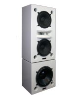
SMPS auxiliary design/startup
- By MJC147
- Power Supplies
- 2 Replies
Hi everyone, just finished my DC-DC amp SMPS project, now i would like to have a go at building an AC to DC SMPS. I will again be using the TL494, driving a half bridge via a gate drive transformer.
The only part of my understanding that im struggling with, is providing 12v auxilary power to the tl494 at startup. I understand that at startup you need to (somehow?) pull up one of the half bridge transistors base, in order to energise the primary and in turn, the auxilary winding.
Surely, one pulse on the auxilary wont be enough to get the tl494 going, also considering that the GDT requires a little current, its difficult?
Also, if the tl494 does manage to startup, i assume that you need to really quickly disable the inital pullup on the chosen half bridge transistor, to avoid shoot-through. Also, if the chosen startup transistor is on for too long, could it not leave saturation issues for when the tl494 kicks in, even with soft start.
At the moment, im considering the option of adding a very small, simplistic self oscillating 12v smps (similar to the sort of smps you might find in a phone charger brick) to the tl494 control board so that it can have its own supply, removing the need for the main transformer to have any auxilary winding, and removing the complication of initial transistor pullup on the half bridge. Would love to hear some relatively simple auxillary ideas 😁.
Hi, pair of Mark Audio MS 11s on there way to me, looking for a wide baffle design for them, any ideas?
- By Herb777
- Full Range
- 39 Replies
Hi, pair of Mark Audio MS 11s on there way to me, looking for a wide baffle design for them, any ideas?
Samuel Groner's super opamp
- By jan.didden
- Analog Line Level
- 300 Replies
In 2017 Samuel Groner, with Martin Polak, published a new composite opamp design: Journal of the Audio Engineering Society ENGINEERING REPORTS, Vol. 65, No. 5, May 2017: Low-Distortion, Low-Noise Composite Operational Amplifier.
Late last year I was looking for a very low distortion opamp and thought I'd give this a try. I laid out a small adapter PCB for a DIL08 foortprint, see pics. The result was all I expected, an opamp with distortion specs literally out of this world. I was not able to verify the claimed THD < 180dB (yes you read that correctly) but got numers at -160dB and better.
I'll post measurements in my next post.
Anybody here build this as well, experiences?
Jan
Attachments
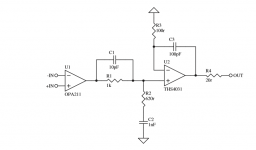


Classic GR Mar-Ken12p
- Full Range
- 5 Replies
Hi fullrange folks,
has anyone a clue about the Fb of the Classic GR Mar-Ken12p - the "Small Reflex" from Scott for the 12p has a Fb of 55Hz
Regards Stefan
has anyone a clue about the Fb of the Classic GR Mar-Ken12p - the "Small Reflex" from Scott for the 12p has a Fb of 55Hz
Regards Stefan
Looking for Valley People QLZ schematic
- By tom31415926
- Analog Line Level
- 0 Replies
I have been gifted an old Valley People QLZ quad microphone preamp (picture attached).
I recall when these came out (1980's) and were novel for having a low input voltage noise without using a transformer. I'm looking for a schematic of the entire unit. I'm thinking of restoring and perhaps modifying the preamp and a schematic would be very useful in that process. I am confident that I could trace out the schematic where standard op-amps are used. I might have found a pinout of the Valley People modules and perhaps that will be enough information to trace out the remainder of the schematic. But if anyone knows where to find a full schematic, please let me know; it will save a lot of work.
Thanks,
Tom
Attachments

For Sale K+K Premium MC Phono Step-up Lundahl LL1941
- By hutchinson
- Swap Meet
- 6 Replies
Not using very low output cartridges anymore,so this Step-up for sale,like new,$400.Assembled by Kevin. SOLD
Attachments
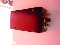
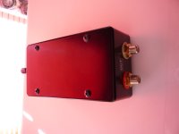
Looking for a fully built DAC (R2R multibit, TDA1541A-R1 etc)
Looking to switch things up and try a new dac. I'm interested in the r2r sound or something more analog like older style dacs. Let me know what ya have.
Powering Raspberry Pi from Bose SoundDock Portable via 30-pin connector
- By Wellco
- Digital Source
- 0 Replies
I'm trying to build a whole home audio system by upgrading my existing speakers, I don't want to throw away perfectly good equipment, and then have to pay Sonos or others a big chunk of change.
So to that end, I have already built a Raspberry Pi ShairPlay device using a RPi Zero and an Audio Shim DAC. It works very well but the external cable and 3.5mm audio jack cables are annoying when I plug it into my Bose Sound Dock. This got me thinking I just need to get a female 30 pin iPod connector, read up on the pinouts, do some soldering and hey presto my old Bose is back in business as a 'Smart' speaker.

I tried to buy a 30 pin connector on line but the merchant was not too helpful and alternatives are few-and-far between, also it was too expensive, so I went on-line and purchased a cheapo weird 30 pin to USB A female lead and proceeded to tear it apart. Here it is after I did some desoldering:

Just like the 30 pin connector itself pinout information is not really out there (come on its Apple right) so I have tried a few things but no success. I need 5v for the RPi to power up, but I have never got this from the Bose. I think there is some kind of hand shaking that has to happen so that the device announces to the Bose what it is and then Bose responds accordingly. The reason for thinking this is that I probed every combination of pin combinations and could only ever find 1.7v
Summary:
Confirmed the iPod Dock works with an original iPod
Analysed original USB cable connections before I tore it apart:
I looked around this forum and others but didn't find anything directly helpful, but I hope that someone might be able to point me in the right direction.
Thanks
Wellco
So to that end, I have already built a Raspberry Pi ShairPlay device using a RPi Zero and an Audio Shim DAC. It works very well but the external cable and 3.5mm audio jack cables are annoying when I plug it into my Bose Sound Dock. This got me thinking I just need to get a female 30 pin iPod connector, read up on the pinouts, do some soldering and hey presto my old Bose is back in business as a 'Smart' speaker.
I tried to buy a 30 pin connector on line but the merchant was not too helpful and alternatives are few-and-far between, also it was too expensive, so I went on-line and purchased a cheapo weird 30 pin to USB A female lead and proceeded to tear it apart. Here it is after I did some desoldering:
Just like the 30 pin connector itself pinout information is not really out there (come on its Apple right) so I have tried a few things but no success. I need 5v for the RPi to power up, but I have never got this from the Bose. I think there is some kind of hand shaking that has to happen so that the device announces to the Bose what it is and then Bose responds accordingly. The reason for thinking this is that I probed every combination of pin combinations and could only ever find 1.7v
Summary:
Confirmed the iPod Dock works with an original iPod
Analysed original USB cable connections before I tore it apart:
- Red (USB 5V) → iPod Pin 23
- Black (GND) → iPod Pin 16
- Grey (??) -> iPod Pin 24
- Green (??) -> iPod Pin 27
- Pin 11 → RPi GND (Audio Switch)
- Pins 15/16 → RPi GND
- Pin 27 → 1kΩ resistor to RPi GND
- Pin 23 → RPi 5V
I looked around this forum and others but didn't find anything directly helpful, but I hope that someone might be able to point me in the right direction.
Thanks
Wellco
DIY 3 way project with Hypex moduls
Hello everyone,
I would like to build a pair of active 3-way floorstanding speakers using 2 HYPEX FA253 modules. For design reasons, the circuit I need to follow is approximately that of the attached image.
What would be, in your opinion, the best combination of drivers (brand and model) that I could choose and find in Europe?
The speakers are intended for a home environment of about 60 square meters. Someone has already shown me that a higher price for the driver does not necessarily correspond to better performance.
True, using the HYPEX modules would allow me to choose three different types of drivers, but at least the woofer and midwoofer should belong to the same product family for aesthetic reasons.
Thank you for the time you will dedicate to me.
Attachments
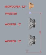
Sjöström SST 01 Rev. 1
- By esprit
- Power Supplies
- 1 Replies
After two years of uninterrupted service, Relay K2 fails to latch.
When power is applied the points continuously bounce.
Anyone help with a solution
When power is applied the points continuously bounce.
Anyone help with a solution
Stuffing's Energy Absorption
I was wondering if the energy that stuffing absorbs is done in a linear way vs power. What I mean is as a speaker is driven to louder output levels surely the energy the stuffing absorbs, becomes non-linear, perhaps by a "saturation" effect? By that, I mean as a percentage, it absorbs less energy as the volume increases? Would this be the reason that many speakers sound harsher as they are driven harder? I realise that drivers and amplifiers distort more as levels increase. If this is the case one would need to use sufficient stuffing to tune the speaker to the levels used at the chosen high loudness levels and perhaps accept slightly too much at quieter levels. One experiment would be to test the frequency response at the same power level with and without stuffing and then increase power to and see if any response changes could be observed when the levels on the plot had been corrected to overlay the first set. If less difference was observed between the with/without stuffing plots, this would reveal the reduced percentage absorption by the stuffing at high power levels.
Targets in REW
I found some targets, but don't know how to save them. I'd like to make a sweep, and compare to the target. How do I keep the target on screen, without resetting it?
Attachments
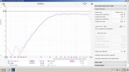
SD to USB converter - how to - (not audio related
- PC Based
- 0 Replies
Looking for advice as I dont know much about the topic.
If I wanted to add USB capability to a device that only takes and reads SD cards, is it as simple as connecting the 4 correct pins to power and data? Or will this need an IC to do some kind of conversion? The only device i found with this kind of configuration is on aliexpress. And while there are lots of SD card readers I can’t find the opposite.
Sorry for my extreme ignorance
Attachments
3-way project idea with bipole bass
3-way project idea with bipole bass.
Hi folks,
I'm highly tempted to try a bipole bass speaker, due to the following benefits:
1. If frames of the bass speakers get mechanically coupled, little force will get transmitted to the enclosure, so less box coloration.
2. Higher, +6dB sensitivity within the bass range due to the removal of BSC correction network.
Now, my first sequence of priorities at first sight seems to be the following.
1. Choosing side-firing bipole topology instead of front-rear to avoid the "bipole" dip.
2. Back and forth looking for a suitable midrange driver to match the BSC-less bipole bass sensitivity, as well as matching the crossover cut points, where the bass driver's directivity at 90 deg needs to be taken into account. How much headroom, will probably depend of the crossover order. What about time alignment, as the woofers will be farther than the midrange/tweeter configuration?
3. Midrange enclosure. At first I was tempted for an open baffle, but I'm uncertain how a dipole and bipole would match. If you discourage me from the OB way, I'd choose a sealed or dampened closed TL as enclosure.
4. For time alignment perhaps building the midrange/tweeter and bass sections in independent enclosures, then sliding the midrange/tweeter section to the rear. Of course that would bring reflection issues of protruding top edge of the bass section reflecting the midrange waves, but that could be treated with felt or perhaps, designed at 45 degrees?
Hi from Tassie Australia 🇦🇺 😊
- Introductions
- 2 Replies
Hi from Tassie Australia 🇦🇺 😊
I am here to try and find some technical help and contribute if I can. Reason for joining, I AM SEEKING SCHEMATICS FOR EV ELIMINATOR 1B Crossover.
Cheers
Ian
I am here to try and find some technical help and contribute if I can. Reason for joining, I AM SEEKING SCHEMATICS FOR EV ELIMINATOR 1B Crossover.
Cheers
Ian
Troubles with my JVC AX-Z911BK
- By Jazzmi
- Solid State
- 0 Replies
Well, great to be with you, here in this fantastic Forum. I'm fortunate to have an old but very good audio equipment, not in the top class, but enough for me. A couple of JBL Monitor Studio 4412 with a JVC AX-Z911BK amplifier, both buy it in 1989. Also I have CD player HD7525 from Harman Kardon, and a cassette player from Technics that I don't use now, M63 with three heads. Well, 20 years ago I repaired my amplifier only changing the 8 power transistors. Now on, again is broken. I try test it only 4 of them, the good ones, but the Relay never switches on. I see the service manual in the troubleshooting, but, my question is: Is this amplifier works on well only with 4 transistors, or needs the 8? I know that maybe obviously the answer is yes, but...The keys to search the trouble are to see components that are far away from the power PCB, so, that's strange and for that, I ask you to all of you, if you know the right answer. Thanks. Miquel Tuset, from Barcelona, Catalonia, Spain, a Jazz Lover!
Hi diyAudio people
- By Jazzmi
- Introductions
- 2 Replies
Well, great to be with you, here in this fantastic Forum. I'm fortunate to have an old but very good audio equipment, not in the top class, but enough for me. A couple of JBL Monitor Studio 4412 with a JVC AX-Z911BK amplifier, both buy it in 1989. Also I have CD player HD7525 from Harman Kardon, and a cassette player from Technics that I don't use now, M63 with three heads. Well, 20 years ago I repaired my amplifier only changing the 8 power transistors. Now on, again is broken. I try test it only 4 of them, the good ones, but the Relay never switches on. I see the service manual in the troubleshooting, but, my question is: Is this amplifier works on well only with 4 transistors, or needs the 8? I know that maybe obviously the answer is yes, but...The keys to search the trouble are to see components that are far away from the power PCB, so, that's strange and for that, I ask you to all of you, if you know the right answer. Thanks. Miquel Tuset, from Barcelona, Catalonia, Spain, a Jazz Lover! Also, thanks for accepting me!
Hello All, is DIY the answer?
- By rexp
- Introductions
- 6 Replies
Rex here from UK, haven't built any electronics since my school days but interested in what some of you guys are doing, particularly in the ADC space.
Aleph J Build
- By yarozebob
- The diyAudio Store
- 1 Replies
Hi I building an Aleph J zen mod(in the process of ordering the parts) and am thinking about putting two transformers in it. Question is is that a good idea? And if so how would I wire it up compared to a single Transformer? Forgive me I’m a total beginner lol
Jaboost Amp - literally "just a bunch of opamps slapped together" dont expect miracles
- By gamerpaddy
- Solid State
- 2 Replies
Things to do when bored:
Open EDA and just throw parts together, see what comes out.
Turns out my third brain cell lead me to making a Amplifier thats just a bunch of opamps slapped together
on a 10x10cm 4 layer pcb. because why not.

PCBs are ordered, and 2 weeks later they showed up, fully assembled.

Its literally just 40 NE5532 in parallel with a 10ohm balancing resistor. its gain is about 8x, non inverting.
the initial idea was to use opa2891 as they can drive up to 200mA (5532 do just 40mA or so) but it would have gotten too pricey for a experiment...
both channels seperated, so each pcb could be used as a stereo or mono bridged amp, or even a symmetrical mono.
a crude +-18V supply was set up from two caps in series with zener diodes across (after i took that pic). not ideal but works.
both inputs are tied together for a bridged single ended amp. output goes into a 8ohm load.

just one channel:
Hooking up a speaker also sounded good, absolutely no hiss or hum audible!
with 2 channels i got about 15W out of it. not great, not terrible.
i dont trust my signal generator for delivering a pure sine, so i later switched over to my PC, fired up REW and set up my Audio interface (focusrite 4i4 3rd gen)

Keep in mind nothing is calibrated, im just interessted in the difference shown in this graph..
the 8ohm resistor has a 1:10 divier across to not blow up my audio interface... 1:10 is a bit much so i had to use the preamp a little.

White noise, peak hold for a few seconds. its not a sweep. but is flat enough for me

I did a loopback from Foobar2000 into audacity trough this amp, into a 8ohm load trough the 1:10 divider and preamp.
it sounded great. at least when i didnt crank the volume into clipping.
Its getting hot, seen at 80°C at max without any cooling or heatsinking.
15W idle power consumption, and 35W at max.

edit:
Oh and the PCBs can be stacked for more current.. at some point its probably even necessary to use a output transformer to step up the voltage. back to the roots of tube amps, just the other way around
Open EDA and just throw parts together, see what comes out.
Turns out my third brain cell lead me to making a Amplifier thats just a bunch of opamps slapped together
on a 10x10cm 4 layer pcb. because why not.
PCBs are ordered, and 2 weeks later they showed up, fully assembled.
Its literally just 40 NE5532 in parallel with a 10ohm balancing resistor. its gain is about 8x, non inverting.
the initial idea was to use opa2891 as they can drive up to 200mA (5532 do just 40mA or so) but it would have gotten too pricey for a experiment...
both channels seperated, so each pcb could be used as a stereo or mono bridged amp, or even a symmetrical mono.
a crude +-18V supply was set up from two caps in series with zener diodes across (after i took that pic). not ideal but works.
both inputs are tied together for a bridged single ended amp. output goes into a 8ohm load.
just one channel:
Hooking up a speaker also sounded good, absolutely no hiss or hum audible!
with 2 channels i got about 15W out of it. not great, not terrible.
i dont trust my signal generator for delivering a pure sine, so i later switched over to my PC, fired up REW and set up my Audio interface (focusrite 4i4 3rd gen)
Keep in mind nothing is calibrated, im just interessted in the difference shown in this graph..
the 8ohm resistor has a 1:10 divier across to not blow up my audio interface... 1:10 is a bit much so i had to use the preamp a little.
White noise, peak hold for a few seconds. its not a sweep. but is flat enough for me
I did a loopback from Foobar2000 into audacity trough this amp, into a 8ohm load trough the 1:10 divider and preamp.
it sounded great. at least when i didnt crank the volume into clipping.
Its getting hot, seen at 80°C at max without any cooling or heatsinking.
15W idle power consumption, and 35W at max.
edit:
Oh and the PCBs can be stacked for more current.. at some point its probably even necessary to use a output transformer to step up the voltage. back to the roots of tube amps, just the other way around
Pioneer SA-7800 loing for help
- By Depaj
- Solid State
- 59 Replies
Hi!
I managed to get hold of great looking pioneer sa-7800 but in not working condition. The output transistors as well as Q24 were blown on one side. On the other side R35 and R59 were shorted and someone replaced R33 and R34 (560ohm each) with 9Mohm ones so I changed all of those. I fired up the amp with, as usual, a 40W light bulb in between. the little flash and then a very light glow as should be, after a couple of seconds the relay clicked. The trouble began when I tried to set the bias, 53mV by adjusting VR5 and 6 and then up to 66mV by turning VR7 and 8. As soon as I started turning VR5 the bulb started glowing way brighter and by the time I got to VR6 (on the other channel) the relay opened up until I got both pots back down. At the same time the vacuum power meter dimmed to almost nothing and a slight noise appeared around the radiator. Even at the bias set at 66mV I have only a few mV of DC before the relay. With the Bias at 0V the amp sounds great and even with one channel up to 66mV (left or right no difference) there is no obvious problem with it.The fault seems to occur when both channels are set at 66mV. All the chemical capacitors are new.
I couldn't find any faulty components and am stuck, if any one has some idea as to what could be wrong I would love to hear (read) it.
Matching Parallel SE output impedance with a transformer
- Tubes / Valves
- 5 Replies
Bare with me for a moment as it is more of a theoretical question rather than something I want to actually build.
If one wanted to parallel SE a bunch of low powered triodes to get a "decent" amount of power without having to buy a big expensive one, lets say 10 of them in parallel.
If one tube has an output impedance of 5k, OT's are readily available.
In our hypotetical case the output impedance is around 500 ohm. There aren't many OT I can seem to find which would have the necesary characteristics. What would be the real life solution to match these impedances? Would you need to make a custom transformer?
Lets take it a step further and parallel 625 tubes together, this gives us an 8 ohm output impedance..Could it theoretically be connected directly to a speaker without the use of a transformer?
Who sells ADC diy modules?
- By Ryssen
- Digital Line Level
- 104 Replies
I know theres one company that sells them but I forgot. Csn you enligthen me?
Load more
Projects by fanatics, for fanatics
Get answers and advice for everyone wanting to learn the art of audio.
Join the Community
508,456
Members
7,920,141
Messages