Is there a correct orientation of Woofer Drivers?

Hi All.

With lack of thought, I disassembled a number of Speaker drivers without noting their orientation to the Loudspeaker cabinets.

Is there a correct side up, or a convention when fitting Woofers?

The Jamo drivers in two of the photos will shortly be refoamed.

I recall a particular tutorial on refoaming speakers.
After removing the dust caps the importance of using shims to centre the voice coil was stressed.
With vintage speakers, he also taught that wherever possible the original dust caps are kept.
These were marked with pencil to also ensure original orientation when later re glued.
He also taught the use of 2 shims at the 6 o'clock position to counter the effect of gravity on the cone assembly.

For this, and possibly other considerations, I thought I'd check with you guys before getting on with the refoam.

thanks

Cliff

Attachments

  • driver 2.jpg
    driver 2.jpg
    292.9 KB · Views: 174
  • driver 3.jpg
    driver 3.jpg
    305.8 KB · Views: 175
  • driver 4.jpg
    driver 4.jpg
    262.3 KB · Views: 173
  • driver 5.jpg
    driver 5.jpg
    257.8 KB · Views: 171

POLIDA2008 A Real Thi.ef on eBay! Fake MOSFETS!

Hi.Days ago i asked seller that items are 100% same as picture and original genuine item.He told me that they are 100% genuine original and same as picture.After this I bought 50pcs of FQA19N20C from Polida2008 on ebay yesterday for Pass diy projects.Here is item
1pcs MOSFET Transistor Fairchild to 3P FQA19N20C 19N20C | eBay
I bought 1 USD each.I told him to send me photos of 10 of these items together.He sent me photo and it is different than the photos.And then he increased the price almost 2 times
And i told him not to send the items and cancel the transaction.And he marked items as dispatched 15 minutes later.Did not make money refund.A real thi.ef
Will never buy from him again.
Never recommended!

Attachments

  • fakes.jpg
    fakes.jpg
    17.2 KB · Views: 1,817
  • look genuine.JPG
    look genuine.JPG
    24.7 KB · Views: 1,797

Free RF Chokes

Hey everyone. I have two RF chokes that I have no need for that maybe one of you radio guys might want or need.

You pay the postage, but they are free if you want them.

Koda

Photos taken on a Samsung Galaxy Note 10+ for those who wonder about photography. Impressive for a camera that's with you all of the time.

Attachments

  • 2020-05-22 08-39-57.jpg
    2020-05-22 08-39-57.jpg
    1,000.4 KB · Views: 113
  • 2020-05-22 08-39-46.JPG
    2020-05-22 08-39-46.JPG
    456.2 KB · Views: 103
  • 2020-05-22 08-40-04.jpg
    2020-05-22 08-40-04.jpg
    804.6 KB · Views: 107
  • 2020-05-22 08-40-25.jpg
    2020-05-22 08-40-25.jpg
    891.4 KB · Views: 110
  • 2020-05-22 08-40-56.jpg
    2020-05-22 08-40-56.jpg
    957.5 KB · Views: 114
  • 2020-05-22 08-40-19.jpg
    2020-05-22 08-40-19.jpg
    995.6 KB · Views: 71

Transistor curve tracer.

Latest project is a transistor curve tracer.
As it stands the software can input upto 5 transistors data and display a trace on the PC screen in a different colour for each transistor.
The hardware simply applies a voltage from 0 to 10 volts through a 1k resistor into the base/gate and the drain/collector voltage is read in via an A2D.
The drain/collector has a 100r resistor to 10 volts to apply a current.
Instead of just the usual set "scope" screen I have used a CAD type screen where you can zoom and pan around to get in close to the action.

The microcontroller uses PWM to set the gate/base voltage through an x3 gain op amp. The micro has a USB interface for passing data to pc.
You can save/load traces and print them out.

How worried should I be about signal < 20Hz?

I'm planning on building a sub to complement my KEF Q150's. This is for listening, not for home theatre; basically to remove the low-end from the coaxials to reduce distortion. I've been playing around with different designs and drivers and it looks like if I have a ported enclosure, the drivers will absolutely shred themselves (exceeding xmax) at a decent volume if there's any signal below around ~15 Hz. Should this be a concern? I was going to use the plate amps from Dayton Audio for their high level input, but I would also enjoy building it myself if it's not too hard (probably from an amp board).


I may also just use a sealed box. Since it's for stereo I'm not expecting much signal below 40 Hz anyway, right? So an f3 of 40Hz would be good enough?

PCBPCBs for Nelson Pass‘ CSX1 SONY VFET amplifier

I posted a PCB layout in the thread „Article – Sony VFETs part 1” which seems to find some interest. So I’ll offer a small run of those boards.

Technical specs:

Epoxy 2.2mm thick with double layer 105µ copper plating, solder mask and silkscreen.
Size: 240mm*107mm per channel
On board there is the VFET circuit plus the Gate BIAS supplies and the regulated main supplies It is provided for either the wired or the print versions of the Jensen transformer.
The transistors are mounted on an L-profile which allows to fix the complete unit directly to the heat sink.

Small auxiliary boards for the BIAS supply transformers and their rectifiers will follow soon.

The price of a set of the amp boards depends on the total order volume. I’ll keep you informed.

I could also supply proper cut-to-length Aluminium profiles 240mm*40mm*40mm, 5mm thick, on request.

Orders are welcome. Please send PM.

Attachments

  • CSX1 SONY VFET_4.jpg
    CSX1 SONY VFET_4.jpg
    730.1 KB · Views: 5,677

Dead A&R Cambridge A60 amplifier

Hi folks,

for sentimental reasons I took a chance on an old A60, £49 inc. P&P. It is the last, 1985 model, smaller transformer and RCA phono sockets for turntable. CD input.

It powers on but no output and speaker fuses are blowing. Also there is a distinct resonance to the case when it is on. No noise, just vibration.

The power supply fuses are fine. When I got it I noticed that the white block that fits in the M.C. option slot was back to front. Hopefully nothing else is wrongly wired! I have only done 6 measurements so far, across the four diodes D204-7 and capacitors C209/10. They all measure around 40v.

Where to start. Any suggestions other than the obvious landfill suggestions welcome.

cheers

FS: WBT Binding Posts

Hi all

I have 3 sets of WBT binding posts.

One set is 4 bindings, 2 red and 2 white (as I see, most of the time, thay sell it like 1 red, or 1 white...) ;

- WBT 730 - Top line (older series of WBT) - would like to get like 120euro
- WBT 730.01 Top line - would like to get like 140euro
- WBT 763 - Mid line - would like to get like 90euro

but I'm open for offers.

Attachments

  • 20191222_091014-567x1008.jpg
    20191222_091014-567x1008.jpg
    135.2 KB · Views: 1,130
  • 20191222_091041-1612x907.jpg
    20191222_091041-1612x907.jpg
    172.5 KB · Views: 1,119
  • 20191222_091028-1612x907.jpg
    20191222_091028-1612x907.jpg
    177.9 KB · Views: 1,128

Subwoofer enclosure recommendations

Some time ago I bought a JBL Stage 1010 and an enclosure because they were cheap and practical. The box is sealed and quite small, only 17 litres, where the manufacturer recommends a volume of 35 litres when using a sealed enclosure. The 225W RMS rated woofer is driven by a 120W RMS rated amp with the gain almost turned to the maximum.

The problem is that the sound pressure at lower frequencies (I think below 80-90 Hz) is very low. I think the small enclosure makes the woofer roll off really early.

Now I'm thinking about building a new enclosure. I prefer a ported box for practical and efficiency reasons. The manual recommends a volume of 28,5L when using a vented box. I find it very strange that the recommended volume for the closed box is greater than that of the closed box. I used WinISD and it recommend me a 22L for a closed box which makes more sense to me. However, I don't really know what I'm doing. Maybe this sub just likes closed boxes.

Can someone help me decide on a box? Or point me in the right direction? I don't really trust the manufacturers recommandations. The TS parameters can be found in the manual I linked.

Thanks in advance.

Hello from Vancouver Island

Hello all,

I have a very specific car audio situation I need help with. Have a 1974 MGB GT and it has no radio at the moment. I'm not looking for an extreme audio system, I am looking to build a very custom system that is non-invasive to the vehicle. If I ever opt to sell this little car, I don't want to have a pile of holes cut into it. Going to post my situation and question in the car audio section (assuming I can with such a low post count).

If nothing else, it will be a "fun build" that "will get built". If people are interested, I will post a photo journal of the process.

Cheers

Voltage presence in phono preamp inputs? Is it right?

Hi guys,

I'd like to ask your advise on this one.
I've built a ESP (Elliot's) P06 phono preamp recently.

While i tested with +/-15V DC power connected and everything else NOT connected (meaning the preamp is not connected to my turntable outputs and my amplifier inputs) i get negative 7mV DC voltage in the RCA inputs of the preamp.
I measured that by connecting my multimeter's red (positive) probe to the center conductor of the preamp RCA inputs and my multimeter's black (negative) probe to the outer conductor (ground) of the RCA inputs.

Is the presence of any voltage in the preamp inputs a normal thing?

I did the same test at the inputs and outputs of my Creek OBH-8SE preamp and voltage presence is nowhere to be found there.

I'm worried whether that voltage presence at the P06 preamp is normal, i don't want to risk my turntable's cartridge.

Thank you for your inputs.

RB300—how flexible should it be?

Hello!
I suspect my old friend, Rega planar 3 /rb300 is, well, ageing...
I am not satisfied with the sonic quality (yes I know, plenty of reasons are possible), and thus recently I installed a new cartridge.

While making the adjustments, I noticed that the arm is not very „responsive“ in vertical movement—when it’s weight was zeroed, the arm‘s movement stopped after 2 up- and down- swings are best...

All other arms I have are much more flexible... shouldn‘t the rb300 be comparable? And could this be the reason for a dull sound?

Battery-Powered Boombox Build From Scratch

Talk about a mouthful, haha. Apologies for the ensuing grammatical and paragraphical mess as sentence and paragraph structure were never a strong suit of mine.


But anyways I'm looking to build a (large) boombox powered by a couple truck batteries with a couple subs, like 4 mids, and a few tweeters to fit across a truck bed and be able to be brought into a garage or taken to a tailgate for a sporting event or a field fire. I'm starting completely from scratch with this project and just looking for advice, insight, and recommendations on the build. If it matters my budget is $1k or less. But mostly I just want this to be balls-to-the-wall and awesome and crazy. The type of thing that'll catch peoples eyes and ears. Make 'em hark back to when they saw their first ghetto blaster way back when. A movin', groovin', big 'ol f'in boombox.


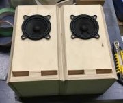
Starting off with the actual box enclosure materials, I could use a fiberboard or other wood type material or I can buy or get scrap sheet steel/ aluminum and have some of my rigwelder buddies stop by on their way to the fields. Biggest problems with that are: Not too timely (not entirely concerned with time) due to welders being pretty much on call and itching for tests and jobs around with the whole COVID-19 situation, and I'm not entirely sure how a metal frame and enclosure would affect the sound. Perhaps a combination of materials? But then again I just don't have a clue about speaker box/ boombox-making.


Onto the components.

Stereo Receiver: I'm planning on using just a basic bluetooth-capable car radio that you can find for around $50 or less. Might end up going with a marine radio for the splash and water rating for peace of mind on my end (but not my wallet's 😀)


Subs: I figured two 10-inch subs should be enough to make the typical bass-heavy music for such atmospheres as tailgates and parties really pop, but if 8's would work great then that would help make for a smaller box footprint and/or more real estate on the boombox for whatever.


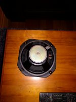
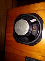
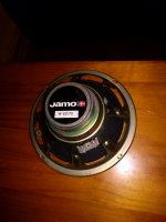
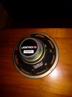
Mid-Range speakers: Those oval/ oblong speakers look pretty slick and would help in giving the box a certain look, but I don't know if they'd be able to really crank up there for a loud music scenario. I'd like for the box to be able to get pretty loud without any sort of audio distortion and grainy-ness if that makes sense.


Tweeters: Figured a couple tweeters dotting the outside would help out with reaching the higher trebles of EDM music along with making some vocals and guitar solos and such really pop.


Power Supply: This is where I'm really scratching my head. Two big 12v diesel truck batteries should be able to power this thing, but for how long? A couple hours, max? I mean I plan on splicing in a 120v AC to 12v DC converter so I can just plug it in and go, but I still have to dig deeper on that. It'd be cool to figure out how to set up the power system so that I can charge the batteries and use the box at the same time without having to plug in to two outlets, but that also comes with having to fit a 12v car charger into the body of the boombox.


Amp for the System: ???? I have absolutely no clue about what sort of amp to use for a project like this.


If it's clear to you that I have only very basic surface knowledge then this post has proven one of it's points. Cuz I'm clueless out here and really in need of some solid advice. I appreciate those who have made it this far in reading. I can only imagine how hard it's been on the eyes.:scared: Also: I had absolutely no clue as to which forum to post this in so if you could clue me in to the appropriate forum for this that'd be great!

show me your baltic birch plywood finishes

I'm getting close to putting a finish on some baltic birch plywood speakers and am really curious to see what others have done.

Please post pictures with a quick description of what you used to get that finish.

My mind is melting with all the tips and advice I've read recently and would like to counter that with actual pictures of what the finished product looks like.

SB Acoustics SB17NRX2C35-4 vs SB17NRXC35-4

I am curious to know how big of a sealed enclosure is needed for the updated version of the SBNRX in order to reach 80hz F3 and what it would look like in terms of response all the way up to 1900hz (SB29RDCN in a 2-way mated to a sealed subwoofer). Good idea or bad idea?

I’m hoping the needed volume is less than for the original version considering they have decreased sensitivity by 2db...

Can anyone help? 😀

Cheers,

David

Attachments

  • 34B66B6C-D5C8-43E9-BF07-20F53EDC7ABF.png
    34B66B6C-D5C8-43E9-BF07-20F53EDC7ABF.png
    719.9 KB · Views: 284

5 Channel EQ

I've been working on following the design found here: 5 Band Audio Equalizer Circuit using LM833 - Engineering Projects

The schematic has a couple of problems I noticed in that it leaves out the feedback for IC4:A and there should be a cap (I think) to ground for pin 2 of IC2:A of .1uF. And when I checked the frequencies, some of the bandpass filter values were incorrect.

A fuzz bit of background, I laid out and ordered PCBs from ExpressPCB. And I've got some experience with board layout and circuit assembly. I've got a Fluke but no o-scope. I'm having some challenges with this circuit and am looking for some advice to make sure I haven't missed something really obvious. I'd hoped this was a cookbook design but it really isn't working out to be that way.

I'm using the headphone jack from a laptop (a Surface sometimes and a Mac at other times). I usually feed amps/receivers with the laptop output at 100%. If I hook this EQ inline then I get a lot of distortion and an unexpected gain. If I turn the output of the computer down to 50% then some of the distortion goes away. I think the gain is causing quite a bit of the problem here.

I tried to use decent components. The only aluminum electrolytic cap I used was for the 100uF C2. All of my resistors are 1/4w 1%. I used tantalum capacitors for the 10uF caps. And cermet pots.

I haven't had a bunch of time to try to measure anything yet (again, wondering if there's something obvious I missed) but am likely to start heading down that route next.

Any help would be very appreciated.

Audio Research HD 220

Freind of mine sent me his HD220 for repair - Blown rectifier was the issue - it had blown the inrush current limiters. Got the Bridge replaced and the amplifier powers up - it however never release the soft start, Ie close the large really to short out the resistor inrush current limiter series connection (which I replaced with a large 12A one)

The indicator LEDs on the face does not illuminate nor does the amplifier unmute. Anyone with a service manual for this on - could not find anything on a search ora none with any experience with these ?

Any input greatly appreciated

Peter

Easiest way to clean up SMPS for powering a DAC

Hi,
I am trying to do my best to maximise the sound quality from my 3e TPA3255 amp build. I have a handle on the basic things like using shielded hook up wire and routing it appropriatelyand having single earth connection to the chassis, but I am wondering whether I should be bothering to use some method of cleaning up the power supply from the SMPS which i'll be using to power my DAC. I have briefly read about options such as LC filters and also ferrite beads. The filters sound complicated and apparently can result in a voltage drop, and the ferrite beads seem to be more effective in controlling noise in the frequency ranges which are much higher than audio range. I am also using a separate SMPS to power my 3255 amp board. Both SMPS switch at about 70kHz.

I had considered using a separate regulated linear power supply just for the DAC but figured there wasn't alot of point given that I am using SMPS for the amp and also I will be using the second 5V SMPS to power a raspberry pi, so I figured that using this to power the DAC would be a simple improvement over using the USB from the RPI to power the DAC.

Generally, the consensus seems to be that SMPS don't affect the sound quality of Class D amps (?much) provided they switch at a high enough frequency. If I am not filtering the power supply to the amp, is there any logic in filtering the supply to the DAC? If so, what is the simplest method.

DAC is a Khadas Tone Board.

SMPS feeding it is this one:
ECM60UT31 | XP Power, 60W AC-DC Converter, 5 V dc, +-12 V dc, Open Frame, Medical Approved | RS Components

Thanks,
Mark

Altec Drivers, Advice/Suggestions please

6 years ago I bought a pair of Altec Flamencos. The drivers appear to be pristine and the speakers sound OK. BUT, the cabinets smell of cigar smoke and mildew and I can't have them in the house.

So, should I just build new cabs the same as the old ones or something all together different and better? I've been thinking of mounting the horn on top a la VOTT. I'm open to suggestions.

Also, anyone know of a source of upgrade crossovers? Or should I stick with stock?

Thx, Steve

WAF Audio Najda reviews

Hi,

I stumbled upon this thread :
http://www.diyaudio.com/forums/digital-line-level/215379-dsp-xover-project-part-2-a.html
whilst looking for an alternative to building & designing an analogue crossover for a 3 way DIY studio monitor i want to make from drivers in PMC designs (IB1S, MB2S).

If you have used the WAF Audio Najda (245 €)
WAF - Wroclaw Audio Force
then please post your review here.

Thanks to all !
Rick

How microphonic are Siemens C3m tubes?

Hello,
read about the microphonic problems with Siemens C3m tubes and there were special damped sockets for this tube available.
Does someone have experiences first hand on this topic? Want to use the tube in the output stage of a line pre.
Will it be necessary to build extra shock absorber sockets for the tubes?

Attachments

  • Original.jpg
    Original.jpg
    31.7 KB · Views: 334

VOIP best practice?

Yes, an IT question as I know there are many IT guys here.

Have to do something with my VOIP phone, the poor quality is driving me crazy. This is my home network, single router, and my home VOIP phone in question.

There's 2 techniques mentioned on the web, one is putting the VOIP modem inside a DMZ, and the other is setting up port forwarding in the router. A little debate as to which is better.

Anybody? TIA

DHT preamplifier

Hi
I hope you are all well.
There are quite a few DHT preamps/schematics, and many of them use Gyrator anode load for DHT, like the one i have attached.

CX301a-DHT-preamp1.png


I was wondering if vacuum tube-like another triode/pentode could be used in place of gyrator to build some kind of MU stage for DHT tube?,
I haven't come across such a thing anywhere, perhaps not possible or make no sense, please let me know if any of you have ever built such a thing?
best.
Kr.

Shingles?

Shingles? The product not the disease.

I thought I would ask the question because there's probably a bunch of members who live in storm prone areas that have more stringent code requirements.

Trying to decide on whether to pay extra for Class 4 shingles for the rental house. Class 4 shingles about 28% higher installed cost than adjacent lower tier from quote. Area is extremely windy, common to have shingle, siding, and fence wind damage. The Class 4 has the same wind rating spec as the tier below it, but I have read web comments that even though Class 4 is about impact resistance not wind resistance, and wind rating spec is same, the shingles have better performance in storm winds.
Anybody? TIA

Shock Wave Electrostatic Subwoofer!!!

I posted this ad from the 90's in another thread and thought it might deserve a thread of it's own. Does it belong in the subwoofer forum or the exotics? Who knows... It is an ad to order the plans for a Lucus electrostatic sub. The ad makes some bold claims and I am wondering if anyone has any experience or opinions with this design.

Attachments

  • lucas_01 (1).jpg
    lucas_01 (1).jpg
    149.6 KB · Views: 1,061

Despacio Sound System - Critiques

Hi all - long time lurker, first time poster. Still relatively early on my audio journey. One of the reasons I'm here at all is James Murphy/Soulwax's Despacio sound system. I've been through most of the threads on the subject and it's clear there's not a lot of love for the design around here, but so far I haven't found any direct critiques of specific things you experts would change about the design. I've found a few things puzzling myself, but considering my limited knowledge I would love to hear what faults you all can identify in this system.

Here are a few links if you're not familiar:
DFA Monitors - Gearslutz (Scroll down for notes from the designer)
klett's Despacio Sound System project page
Inside Despacio – the world’s greatest sound system


A few oddities I noted:
1. Crossover frequencies seem odd based on component choice (hi-mid horn upper and lower XO point in particular, as well as the low mid-hi mid point in general given the low mid is using 12" drivers)
2. 12" drivers for low mid (would start to beam at about 1.3khz, no?)
3. Vented bass and low-mid cabinets (guessing that the crossover freqs are well above the inherent tuning frequency in the "minimally tuned" design; why vent at all, or why that way?)

Some critiques I've read here that I had thoughts on:
1. This system was clearly designed to be 1) old school, and 2) excessively and visibly lavish. McIntosh amps probably have little business in this sort of application, but the target audience (myself included) thinks they're pretty cool and fit with the ethos. More practical choices abound... but that wasn't the point.
2. The system was a DIY-style project from the beginning. In one of the articles above Klett talks about franken-klipsches as the genesis of this. Fair to say the were trying to avoid the latest technology. When I think of vinyl DJ's (love it or hate it) I don't think of Void or L-Acoustics.

Final thought - I've tried twice to hear this system live, and been foiled both times, the latest being the NYC show last month that was postponed for... well, you know why. Would love to hear the thoughts of anyone who has seen/heard it!

Sansui amp keeps blowing fuses after output transistor replacement.

Hello everyone.
I'm trying to fix my old Sansui AU-117 (first edition) since the left channel is nearly dead on the output (very low volume noisy distorted sound).
The headphones work as they should on both channels and the right channel sounds good on the output speakers.

I replaced all the electrolytic capacitors, but still the same problem. The driver transistors have no problem as far as I'm concerned since there is good sound from the headphones.

The BIAS settings should be 20mA and 13mV. I tested the right channel and the readings were correct but when I tried to check the left the readings were far off and the pot was not adjusting the voltage level more than 0.5mV. And I left the bias pot to a certain voltage and current setting I can't guess (since the obvious problem was around the output transistor).
So I decided to test and replace the output transistors for the left channel.

There are two main output transistors per channel (plus 2 smaller ones I would replace if the first replacement didn't work well)

1 x 2SD313 and 1 x 2SB507.
I took all of them off and I measured them and everything seemed good for both channels' transistors, but since they are more than 40 years old I decided to change the left channel ones.
Impossible to find these transistors near me I bough 1 x TIP41C for the 2SD313 and 1 x TIP42C for the SB507.
After I replaced the 2SD313, I powered the amp but it immediately blew the fuse (it hadn't happened before, after 3 days of testing). I decided to change the bias pot setting even if it's impossible to make any measurement since the amp blew a fuse (by just putting the screw marker at the same point where the right channel's one is).
I replaced the fuse and powered it on but it blew the new fuse again. I replaced the new transistor with the old one (I thought that, even if it may be damaged, it didn't blew fuses and it would help me to see the current BIAS readings to adjust them). I changed the fuse and powered the amp, but it once again blew the fuse.
So after a couple of more blown fuses I decided to check the power rectifier diodes. They are of IR10D type (something like 200V, 1A) and I found one out of six being bad. No reading on both sides. Since I have some spare 1N4003 I 'm thinking about replacing the IR10D with one (they also are 200V, 1A), but I'm not sure if they are the correct type for the job.

So what do you think about the situation? Any advice? Where the problem could be? Are these N4003 diodes ok for the job (replacing just one and leave the rest IR10D).

Sorry for the long message. Hope I didn't confuse you and thanks in advance for the interest.

WTB: 1SV68 or equivalent Varicap / Varactor Diode

Hello, hoping that someone out there is sitting on a suitable varactor diode so I can repair this wretched tuner once and for all.

The original part is 1SV68-08 according to the manual. It is a Pioneer TX-710-2 tuner.

I will happily pay a fair sum for the part and postage (I am in New Zealand) Can even send back a postcard, if that does it for you 🙂

I have managed to find NTE614 online, which is apparently an acceptable substitute, but any kind of "parcel" shipping makes it an expensive proposition.

Hoping someone can help a fellow diyer out 🙂 Thanks in advance!

edit: Have realised this is probably in the wrong forum 😛 hopefully a friendly mod can move it across (rather than me double posting)

Vented box acoustic parameters?

Vented box acoustic parameters??

I am about to add a constrained layer damped aluminium plate to the baffle of my woofer & sub enclosure.
That will make it impractical to modify the boxes so I decided to check they were tuned correctly, before I did any irreversible work.
At that frequency it's most practical to determine the resonance with an impedance test rather than use a mic.
So the result is that I have restudied the way the acoustic parameters are reflected (or transformed) into the impedance curve of the speaker.
I did the calculations for the speaker years back, by hand but must admit I didn't have a real intuition for the acoustic parameters.
The "acoustic mass" of the port is in kg/m^4, not just a mass.
Similarly the acoustic compliance is m^5/N.
I understand they are multiplied by Sd^2 to become mechanical units but these are not intuitively obvious units to me.
Anyone here have an explanation of this?

I read Olson and Beranek back when I did the calculations, now a quick check with Vituix* showed I did pretty well.
But I never had a real feel for the work.
Now I have a copy of Marshall Leach but I don't find the presentation very clear.
I also have LSDC by Dickason but the focus is on how to use software.
Software wizards means almost anyone can achieve a reasonable result but it is not very educational just to copy the recommendations of a black box process.
Anyone know books, articles or websites that explain this better?
I can do the maths and physics but I want to understand more.

David

*Excellent piece of work, my compliments to the author.

Need a new or a second transformer..

Have this preamp i really like after some mods but the transformer seems way underdimensioned. After replacing op amps from NE5532 to opa1612 i noticed temp rises.. now Around 45-48 degres celcius or 113-118 F. After some 1-2 h playing music.

Think they saved some money here and logic section (volume, relays and all) take its power from same. See schematic.

I mesured voltage and with load its 27.5V ac and 30.5v ac without load.

My idea was to use only the orginal one for logic and add a toroid or something similar to feed audiocurcuit separatly.

But i can’t find a toroid that has centertap and 27.5v, i find many 2x25 and some 2x30v (Noratel/ multicomp) maybe some 20-30va? Some 1 amp rating would be enough. I’m not sure how to calculate current rating here. But the whole preamp sucka about 13.5w from the wall in standby with no music.

Can i use 2x25v for both (if i wanna change to toroid for both for example?)
The 7824 doesn’t need some min 26.5v to regulate well?

And with my limited knowledge a 2x25v can easily be connected with a CT just connect the 0 together from both windings?
Also is it possible when using 2 transformers to let the centertap be to same ground?
Anything i should think about regarding fuses? Now there is 2x800mA.

Hope to learn something new and same time improve the sound a bit.

Regards

Attachments

  • D750319B-0A12-4194-9DC4-8465E5248E65.jpeg
    D750319B-0A12-4194-9DC4-8465E5248E65.jpeg
    660.6 KB · Views: 176
  • 6911FFF3-C577-423A-B611-B1BDA80C3E5B.jpeg
    6911FFF3-C577-423A-B611-B1BDA80C3E5B.jpeg
    555.6 KB · Views: 176

Removing Loudspeaker Cone Dust Caps without using a razor?

Hi All.

I was hoping to remove the dust caps of 2 Jamo Loudspeaker Drivers I'm refoaming.

Would prefer to remove them without cutting, as my options will be to re glue the Caps after the operation, or replace them with new examples.

I prefer to re use the originals, but they are both spotted with mould.
They also appear to be of the woven variety rather than solid, and over the years may have lost their ability to be as air tight as they were when new???

If I do replace them then the ring of the old Caps will remain on the cones and might affect sound.

Can the old Caps be removed, by soaking with acetone, or will this damage the cones?

The replacement Caps appear to have a woven texture underneath but more solid in appearance on their domes.


thanks

Cliff

Bryston 4B NPB Bias Setting and modern Transistor info

Since this info has been elusive at best I want to leave it here so the internet remembers for further readers. (and maybe not that experienced at this)

So, I spoke with Mike Pickett (great as always) and the instructions are like this:

Transistors were SJ6521A/22A and they were a special commission for Bryston, since the standard ones did not meet what Bryston wanted at the time. Some people still like the sound of those so you can always ask them to send those. Nowadays, the replacement would be MJ21193G/94G, made by ON SEMI. Mike said these actually have better specs and that you'd be alright with them. You can not combine them, tho (on each side). Each side must have all of the trannies the same type. Better off if the whole amp is the same type.

Now for the biasing procedure, it is done with the 2k2 pot. First off, let the amp idle for a while with no signal. When it gets to a stable temp, adjust DC offset with the other trim pot (Blue bourns multiturn 10K) and let it stabilize with each turn. When you have the DC set, then set the bias pot so the test points TP1 and TP2 measure each 12mV average. Let the amp sit after each adjustment for a while. Maybe 10 min or even 20 if you have time, until you have that average 12mV after it is idling for a while.

That is it.

Hi from a Amp-newbie

Hi all, I’m new to the audio scene, helping my daughter fix her Peavey Renoun 400. Replaced the Power supply smoothing caps and it came back to life. Still working on cleaning up the pots but it is going ok so far. My background is in electronics and have a scope and multimeter plus general tools. Kinda fun tinkering around with it.

Looking for advice on where to get the correct schematic as ours doesn’t quite match the board. Heard there are a number of versions of the 400, so any tips on identifying the beast would be appreciated.

Also, apart from ‘just playing guitar’ through the amp, is there a formal test procedure or burn in for these amps?

Looking forward to being part of the forum and happy to help where I can.

Cheers, Graham

Broskie Four Way Series-Shunt Crossovers and resistance values.

Re Broskie Four Way Series-Shunt Crossovers and resistance values.

This is an interesting article with a revised series network topology.

New Crossover Designs

All values in the article are all for 8 ohm values of R but what if you are using drivers with a different values of R?

Assume a 4 way design using a 4 ohm bass / 4 ohm upper bass / 4 ohm upper mids but an 8 ohm tweeter.

Am I right to assume that in theory the component value for the treble C1 will remain as calculated, but that all other component values will obviously change due to the 4 ohm R values?

Usually if impedance R halves then inductor values halve and capacitor values double. Is this the case here?

The only one that would not change would be the 8 ohm tweeter C1 which would still be a 5.6uF capacitor.

Math here

C1 = 159155/R/F3

C2 = 159155/R/F2

C3 = 159155/R/F1

L1 = 1k*R/(2*pi*F3)

L2 = 1k*R/(2*pi*F2)

L3 = 1k*R/(2*pi*F1)

Much fun

Broskie%20Four-Way%20Series-Shunt%20Speaker%20Crossover.png


Broskie%20Four-Way%20Series-Shunt%20Speaker%20Crossover%20Design%20Example.png

FS Dynavector DV-10X5

For sale a Dynavector Dv 10X5 high output MC cartridge in superb condition with max 60hrs of use, it came with a Thorens TD 126 mkiv that I bought from a good friend a couple of years ago (the one you see in the last photo), he had bought the cartridge as new put it on the turntable and after three months he sold it to me.

I played just a couple of records with it and after that I replaced it with a Benz Micro Wood SL I already had in my collection, since then it stayed stored in my drawer.

I own three different turntables and some more low output mc cartridges that I prefer so time for the 10X5 to find a new home.
Magnified photos are taken with my digital microscope.

Asking 320 euro (paypal friends and family) shipped.

The cartridge will be shipped worldwide by post, registered mail with tracking number and signed for.


20200218-154530.jpg
20200218-154513.jpg
20200218-154549.jpg
20200218-154613.jpg
20200218-154656.jpg
20200218-154842.jpg
Tue-Feb-11-13-12-27.jpg
Tue-Feb-11-13-18-07.jpg
Tue-Feb-11-13-19-58.jpg
Tue-Feb-11-13-21-03.jpg
WIN-20200211-13-53-47-Pro.jpg
79374316-1021573708209136-3001328283225686016-o.jpg


Sudden Whine in System After Shutting the Engine Off

Hi, I've been dealing with a bit of a whine coming into my system after having the engine on for a couple of minutes. I've already tried searching various forums looking for other posts w/ a similar issue, but I haven't found any.

I'm running a Pioneer AVH-2550NEX headunit
Alpine PDR-v75 four channel amp
Kicker KX 800.1mono amp
4 gauge power/ground wires
12 gauge speaker wire for all of my drivers
- I'm using a wire from accessory to trigger a relay for my remote wires
I'm also using a power/ground distribution block to power and ground my amps

I don't have any noise when I play audio while my car is off or engine is running. I will only get noise when I keep my headunit on after shutting my engine off. I have to move my key from accessory to the off position to stop the noise because simply powering the headunit off and back on doesn't stop the noise (if the key isn't moved from the accessory position)

Disconnecting the RCAs from my four channel amp will stop the noise
My head unit is grounded to its mounting bracket, which has a factory ground wire connected to it as well.
I already ran a cable from the grounds of my RCAs on my deck's grounding point.
The RCAs are new
The headunit was recently replaced (warranty replacement because of a blown pico fuse)
My relay is grounded to my ground block
RCAs do not run parallel w/ my power wires

I do have an extra ground cable from my negative battery post going to my inner fender wall, which I'm now thinking about removing.

Again, the noise only comes after the engine has been shut off.

Thanks in advanced for any advice

Identifying enclosures for the Faital Pro 3FE25

I've been looking for a desktop purposed speaker with the 3FE25 or the DA RS100-8. Planet10 has a really nice reflex slot for the RS100, but PE is still out of them. My second choice and still popular 3FE25 drivers are worthy. I found a link with the enclosed pic of what appears to be the 3FE25 but can't find any cabinet dims for this one. I think this would do well in this kind of setting also. Any help in narrowing this dude down would be appreciated.

Attachments

  • faital pro 3fe25 desktop speakers.jpg
    faital pro 3fe25 desktop speakers.jpg
    7.4 KB · Views: 312

TPA Retro vs Passdiy Pearl 2...

Hi!

I'm still a relative DIY newbie and am looking to build a solid state phono preamp from a kit. I've been looking at the Twisted Pear Audio Retro and the Passdiy Pearl 2.

Just wondering if there are any general opinions on the two preamps. At the moment I'm leaning towards the Retro as its balanced (and I'll have to mod my table as well) and there's no mention of it being inverting. I think the cost may also be less than the Pearl 2. I haven't found any comparative sound impressions though.

I know that this will probably be a 'build both and let us know what you think' thread, but I was wondering whether there were any general opinions.

Thanks!
Taz.

In pursuit of the best speakers

Hi all, there's something that has been bothering me for a long time. Some people will spend a fortune on audio equipment to reproduce sound as close to the original live performance as possible. But is there really a point in doing that? How do you know what microphone was used recording the audio? What is it's frequency response? After that it got mixed in a studio by an audio engineer, whose ears might be more or less sensitive to certain frequencies, who adjusted it to his own taste based on that and listened to it on his own speakers. So by the time you play that CD it will be far from the original live performance. And there are your ears that will be more or less sensitive to different frequencies. How can you make sure that a microphone has a flat frequency response and that a speaker has a flat frequency response?

Is it a broadcast inductor or a constant type.

I have two Freed inductors sold in this case as Hazeltine. It has the number FR1120 for Hazeltine and 2237112 for Freed on the 2 chokes rated at 2 Henrys, measuring 10 Ohms each, and looks like they have been "Tropicalized" in military terms, sprayed with an opaque protectant all over. I also have a Paeco 712-1 rated at 36 mH and measures .3 Ohms, and is open framed and NOT tropicalized. I'd like to use them in audio. Good idea or bad idea? Thanks in advance for your consideration! buffstereo1/aka Robert

Elekit TU-8800 Tube Amplifier

Selling an Elekit TU-8800 amplifier with Takman resistors, TKD volume pot and Mundorf Silver/Gold/Oil coupling caps. Unit was expertly assembled myself using TRT Wonder ultra clear solder.


Full transparency, the amplifier functions correctly aside from a low level hum at both speakers when your ear is placed close, which is discussed at length in the link below. Thinking the amp doesn't like being fed with mains voltage above 120. Work is relocating me overseas, so I have no time to further pursue getting this one issue resolved. Interestingly there is no noticeable hum when headphones are used.


ELEKIT TU-8800 SET AMP


All original packing, documents, screws, tube cage and front plate are included, though I have misplaced the volume knob and unsuccessfully attempted to paint the top cover black. The original color underneath has not been sanded or primed, so paint remover should bring it back to original.


Not sure what to ask price wise, so the amp will go to the highest bidder.

Attachments

  • 1.jpg
    1.jpg
    868.8 KB · Views: 597
  • 2.jpg
    2.jpg
    866.1 KB · Views: 586
  • 3.jpg
    3.jpg
    893.7 KB · Views: 572
  • 4.jpg
    4.jpg
    843.9 KB · Views: 561
  • 5.jpg
    5.jpg
    873.2 KB · Views: 558

Returning to 'proper' HiFi...

The Situation

I am an ex-musician/ex-budget audiophile (see my intro). I live in a fairly small apartment (on a noisy street) with a pretty tight listening space in my living room area. It is split between a content creation/streaming/gaming studio and sofa/tv area. It has been many years (about 20) since i've had a proper HiFi setup. I moved around so much here in the States and abroad over the last couple of decades that it became practical to get rid of big heavy HiFi equipment in favor of smaller more practical stuff (headphones, small speakers etc).

Now i'm in a city that I will likely settle down for awhile and possibly buy property in the future. Since i'm currently working from home, i've started to reevaluate my HiFi situation, a 60" 4k tv, using built in speakers. That's pretty much it! Paltry, I know. This needs remedying...

My needs as an audiophile

I'm not the super esoteric type. I desire crystal clear, accurate, efficient, spacious sounding audio with a nice wide soundstage and good imaging. If I can achieve this in the small space I have, with a small to medium sized (bookshelf or free standing towers with a small footprint) setup, I would be totally happy. I have some light electronics engineering experience in my distant past, so the idea of DIY appeals to me.

Possible Solution(s)

I want to do one of two things:

  1. Build a DIY flat pack/break down speaker kit with possible mods to achieve my goals. I don't have the space or tools for woodworking, so pre-built cabinets are required. I am currently considering 3 kits:
    A - The Swan/HiVi 3.1 with a modded crossover to tame the slightly bright nature of that AMT tweeter.​
    B - TriTrix MTM Transmission Line Kit. These are much larger than the first option, but chances are I would have option 1 on stands anyhow. These may actually be too big for my space, but i'll be moving into a larger space sometime later this year or next, so the solution needs to be scalable to some degree...​
    C - The Dinas - These are powered and seem like they would be a bit on the bright side, but an intriguing option. I'm not sure yet if I can buy the cabinets pre-built or flat pack. Have contacted the designer of these to find out...​
  2. Restore and/or rebuild some vintage speakers with updated crossovers and drivers. This appeals to me only because many of the great vintage models that existed when I was young. I had the experience of hearing many of these having worked in the HiFi retail industry in the late 1980's as a teenager.

Question to the community

I'd like to hear some opinions on the way forward here. I'm going to need the solution to work well at low, as well as normal volume listening with very low distortion. I have not given too much thought to amplification yet as I wanted to focus on the speakers first. Off the top of my head i'm thinking either a class A/B or D solid state amp in the $300 - $400 range.

Any ideas? 🙂

Behringer DDM4000 Issue and Repair Ideas

I recently got a used behringer DDM 4000 DJ performance mixer and while testing I found that the channel 1 inputs (both phono and line) seem to only allow left signal to get through.

There is a small amount of signal in the right channel, but I'm not sure if it's bleeding through.

Is this something that I should be attempting to repair myself? What might a likely component that failed be? Capacitor? I'm pretty good with the multimeter and soldering iron.

Thanks agin.

swap 2sc5200/2sa1943 to MJL21193-94

Hi guys,

I have a friend who gave me a low powered PA amplifier to repair which is blowing the main rail fuses after it got slightly wet while turned on, and the music just stopped, no bang or anything so he turned it off and used a hairdryer straight away to dry it.
After finding a C-E short on one of the output PNP transistors I desoldered the lot - the rest of the unit powers up fine and nothing else seems affected (yet!)
I always replace the entire output stage when I do a repair and I don't have any 2sc5200/2sa1943s on me, only mjl21193-94 - Is it safe to replace the output stage with these? The transformer puts put 35-0-35 so im guessing it has about 50v rails - so I am pretty confident but still need that little peace of mine.
There are 2 complimentry pairs per channel.

Thanks very much for your help.

Alternator noise '03 Porsche MOST fiber optic adapter

I put a cheap ebay double din head unit in my 2003 Porsche Carrera. It would not make any noise, so I found that I needed an adapter for the MOST fiber optic system that runs the amp. I bought that and indeed I now have sound. However, I have a very annoying alternator/engine noise coming through the system. So far I have tried significantly improving the grounding system and changing the power (b+) location. Right now I am using the cigarette lighter wire, which stays on all the time in this car. For an accessory wire I am using a small one that runs to the exhaust cutout system switch. I suppose this might be the problem but I doubt it, because to my knowledge the switch only disables the system.

I now have soldered connections almost everywhere, with the exception of the actual two power plugs and the ground, which I anchored securely (I believe) into the aluminum brace of the dash.

The MOST adapter is a little box with b+, acc and ground. The fiber optic plugs into the back, and has RCA plugs that go to the head unit. It only uses L/R plugs, so this system cannot fade.

Will RCA jack noise reducers work in my case? What else should I do?
Projects by fanatics, for fanatics
Get answers and advice for everyone wanting to learn the art of audio.
Join the Community
507,743
Members
7,886,381
Messages

Filter

Forum Statistics

Threads
406,148
Messages
7,886,381
Members
507,743
Latest member
Fitodiod