Spendor SA3

Hi, hoping to find some more information on this design. It had a proprietary bitumen damped 12" woofer and a 1,25" Audax tweeter.

The 12" looked through a wide rectangular "diffraction slot" supposedly to enable the heavy cone to extend to 1.5khz with a more even on and off axis response.

Given the aperture size I am a bit dubious as to how effective it was but can find no information regarding any dispersion improvement.

If anyone has information regarding this aspect of its performance.. the design paper by Spendor perhaps, or links to it, I would love to see them!! I understand hifi choice did a review and I think hifi news and may be others. Any links would be much appreciated!

Need help. Power supply (B+) problem.

I am building a VTV Octal Preamp. I followed the schematics, and need to figure out what I'm doing wrong. I'm using a Hammond 370BX PT instead of of the 270. Because I need the multiple inputs to wire for my mains voltage of 230VAC.
I have 2 of 370BXs. So I was able to compare them to each other.

Using a Variac & Dim Bulb (40WATT)
Dim bulb will glow a little brighter than I expected because of filaments?

When testing the power supply assembled:
With out Rect. tube: No glowing of Dim Bulb.
Pins 4 - 6 (584VAC)
Pins 2 - 8 (5.31VAC)
Green wires (6.7VAC)

With Rect. tube: Glowing of Dim Bulb. Not really bright.
Pins 4 - 6 (4VAC)
Pins 2 - 8 (1.85VAC)
Green wires (2.62VAC)
A & B leading out of Power supply ( 9VDC)

Michael

Attachments

  • vtv-octal-ps (1).jpg
    vtv-octal-ps (1).jpg
    110.6 KB · Views: 161
  • 230v-primary.png
    230v-primary.png
    3.4 KB · Views: 159
  • 370BX.pdf
    370BX.pdf
    291.4 KB · Views: 63
  • 20200620_094235.jpg
    20200620_094235.jpg
    763.5 KB · Views: 152
  • 20200620_094326.jpg
    20200620_094326.jpg
    996.7 KB · Views: 154
  • 20200620_094552.jpg
    20200620_094552.jpg
    890.3 KB · Views: 140

  • Locked
Deleting/disabling an account

I am opening this post to ask the Admins of the forum to disable/deactivate my acccount.

I no longer wish to be affiliated with the forum and have a right to NOT be considered as either an active member or a registered regular user.

I have noticed a steady increase in the level of verbal violence and aggressiveness and no longer wish to be seen as a "part" to this forum.

I asked a moderator to respect my wish but was not granted this simple right.

http://www.diyaudio.com/forums/forum-problems/141244-account-deletion.html

it has been done in the past. I ask for it to be done again.

Alessandro

DI noise only with passive instrument

I recently was given a Jensen DB-E transformer and decided to try my hand at building a simple direct box based on their schematic. I’ve done some basic projects before but I’m certainly not and expert and I’m stumped by this problem. When I plug in a bass with an onboard active preamp, it sounds great. When I plug in a passive bass, there is all kinds of noise. Ground buzz type noise. I have a couple basses that can switch between active and passive. In active mode, great. In passive mode, buzzzzzzzx.

I thought it might be a ground loop issue but lifting the ground has no effect. Only thing that changes it is when I turn the volume down on the passive basses, the buzz seems to get louder. Any ideas???

Simple 5670 tube based line stage design help

Hello,


NEWBIE on board😉


I'm building a simple 1 tube preamp based on 5670 tube (see the attached drawing) and would appreciate any suggestion for getting the best out of it.
with any lower cathode resistor than 2K I'm getting distorted output.


Any suggestion from experienced members will be appreciated.
Thanks

Attachments

  • 5670 preamp.jpg
    5670 preamp.jpg
    18.7 KB · Views: 748

Rcommented cost-effective OPT for PP EL84

Hi Guys,

I'm on my way to build PP EL84 amp based on Audio Note EL84 PP "inspired" PCB available in Aliexpress. It looks like a clone of the ANK Audiokits L1 EL84.

I'm straggling to make up my mind regarding output transformer. I’m looking for something economic, but not disappointing. There are so many options and I cannot make up my mind. I assume the experienced of you can give some orientation.

To start with, EI, C-core and toroids are offered- would you prefer one structure over the others?
Regarding suppliers- I read about Hammond (which are not liked due to their frequency response), Edcor, Lundahl (which are beyond my budget) and many other in between like Toroidy.pl., Triad.
On Ebay I can find old stuff like Siemens Klangfilm and some super cheapos from Indonesia or China.
You got the point… will appreciate any hints. I would like to stay below 100$ per OPT.

Another question- which power rating would be suitable for this design?

Regards,
Aviv.

Panel and cable mount connectors for low voltage power

Hi all 😀

I'm looking for small connectors for low voltage power umbilicals (mostly 15V, occasionally 24V).

I'd prefer options for male and female for both the cable and chassis mount parts so there are no exposed power-carrying pins. I've used XLRs in the past, but I want to avoid possible confusion between power and signal.

I'd love to go for the likes of Lemo, but those are way out of budget at present. I've looked at the usual GX12 / GX16 aviation connectors, but the ones I've found thus far are all male on the chassis mount. The Bulgin 400 series parts come very close, but the need to buy separate contact pins, insertion tools etc. is a pain.

Does anyone out there have a recommendation?

Control of DIY amps via phone

I searched awhile this for this but I would like to control my DIY system from my phone maybe via bluetooth (?) elementary stuff turn on and off equipment. Maybe a few other functions I haven't thought of yet. I have remote control on my dac that takes care of volume and streaming functionalities. I want something more flexible than just another remote control and use from single device. Any suggestions are appreciated.
Thanks.

Hafler DH 220 amplifier

I put together a home system yesterday with a Pioneer VSX-932 AV Home Theater system, Sony PS-LX5, Hafler DH-220 driving a pair of B&W BM602's.

The problem is when I have the Hafler in the loop (between the HT sys and speakers) it has good audio but too loud even with the HT turned down to minimum.

I started with an older 80's Harmon Karmen Receiver(don't recall the model) in place of the HT sys, and same thing. The Harmon Karmen has some pot issues and decided to swap it out with the Pioneer.

So, does anyone know what I'm doing wrong? Shouldn't I be able to turn down the sound down to low or off? Is the signal to hot from the Pioneer? And why would the HK be so hot using the phono inputs?

Tabletop testing a Hypex NC400

Hey everyone,

I have a common question with the NC400 and after reading the manual and searching the forum I haven't found a direct answer.

I've received my NC400 amp from Europe but the enclosures were not available so I'm waiting... While I'm waiting, I'd like to make sure that the amps are working OK with the rest of my gear and make sure I wired everything up correctly.

I've connected all the pins, powered it up, and the red LED's appear to be all on. But I can't get any sound. I can hear a very very quiet playback through the compression horn on the speaker if I put my ear up to it.

I'm guessing this is because the amps are in standby due to nAMPON you're meant to ground to the enclosure.

Is there anywhere I can temporary connect nAMPON and get the amps out of standby without an enclosure?

I've soldered on XLR inputs with white, blue, and ground to the appropriate pins. I'm using an XLR to RCA adapter cable for input from a DAC with volume at 20%.

Please tell me a reasonable number for the RC of a KT88 PP output stage.

Hello,

I am trying to decide on a reasonable number for the corner frequency for the RC of the output tubes(KT88/KT120) PP. I found numbers in the range from 1 to 33.9 Hz - see attachment.
I know the resistor value is basically set by the datasheet. Please tell me a reasonable number for the f3dB frequency.

Edit: there will be no global negative feedback

Attachments

  • KT88_f3dB.jpg
    KT88_f3dB.jpg
    39.1 KB · Views: 203

SynergEx: Point Source Experiments

I got inspired by all the synergy builds and thought I'll give it a go. Getting the courage would not have been possible without your (Tom, Mark, Chris, Bill, xrk971, nc535 and many more I forgot to mention) excellent work.
I was going to go with synergizing the K-402 horn route, and talked to a local dealer. But it's a no go at $4K, I could buy a lot of driver for that kind of dough.
Just a warning. I'm a total newbie when it comes to designing, measurement and software. There'll surely be some bone headed mistakes and DUH moments. But I'm committed to listen and learn from everyone's experience and expertise.
I'm going to stick this in a corner and hope to go down low enough without a need for subs for music. One 15" for now, dual 15 if needed with BMS 4592 or 4594he.
It's a work in progress, slow going due to full time work and keeping the wife happy with home renovations. Finish a bathroom, build a horn kind of deal
Here's what I have so far, one thing for sure it's MASSIVE!!!

Attachments

  • synergy1.jpg
    synergy1.jpg
    375.4 KB · Views: 116
  • synergy2.jpg
    synergy2.jpg
    404.8 KB · Views: 123
  • synergy3.jpg
    synergy3.jpg
    412.2 KB · Views: 114

Single Ended 45 Amplifier

Greetings!

I am very interested in building a Single Ended Output
Transformer-less 45 tube amplifier with the fewest parts possible. I
would be very appreciative if you could either give me some guidance.
Please excuse me ahead of time for ignorant questions but I am still learning.

What is the minimum number of tubes I would need in an OTL design? I
am okay with low power output of 1-2 watts per channel.

I did not think this was possible but in a "Boy's First Book of Electronics" a schematic was provided for a one stage amplifier with only one 1h4 power tube and no driver tube or rectifier tube. Would it be possible to drive the power tubes directly from the preamp in an iPhone instead of using the driver tubes?

Bluetooth Apple AirPods use two separate wireless channels for the L & R channel. What would I need to use one audio source (ie iPhone) and
connect to two mono bluetooth devices (one for each channel L & R)?

Stax headphones use a bias of 230v and 580v in "pro" versions. Is it possible to build electrostatic speakers that use a voltage of ~250-300v?

Kicker 700.5 no sound

Hello good night, friends, I have a kicker 700.5 amplifier in my workbench and it does not emit sound, I found some j fet transistors (j108) that would like to know what their function is in this amplifier, because when I remove them it works wonderfully, they are the Q23, Q301, Q401, Q501 and Q601. All J108 if someone could guide me on their role in that part. Thanks for help me.

Attachments

  • Screenshot_20200609-223003_Gallery.jpg
    Screenshot_20200609-223003_Gallery.jpg
    217.2 KB · Views: 66
  • Screenshot_20200609-222701_Gallery.jpg
    Screenshot_20200609-222701_Gallery.jpg
    584.9 KB · Views: 66
  • Screenshot_20200609-222712_Gallery.jpg
    Screenshot_20200609-222712_Gallery.jpg
    349 KB · Views: 62

Speaker Circuit Question

Hi everyone. I am building a center speaker designed by Paul Carmody. I would like to know what the inductor in the picture affects (red arrow in pic below). Does it require the woofer on the right channel be positioned on the inside/outside? Thanks!


IQdwiRx.jpg


Here's a pic of the speaker.


An externally hosted image should be here but it was not working when we last tested it.

iujwojq.jpg


An externally hosted image should be here but it was not working when we last tested it.

LM3875 taming

Chip has been obsolete for years, but there are still quite a number around.

I have of the luxury of VNA and was re-purposing an early 2000's amplifier which required stability.

Under any circumstance, the LM3875 seems to need a 15 to 20pF compensation capacitor across the feedback resistor. The design in the datasheet may not have been checked up to 10MHz.

fiber optic cable jacket diameter?

Greetings,

Does anybody know some typical outside diameters of fiber optic cable jackets? I am asking about the cables used by internet service providers to get service to the subscriber's house.

background:

I am getting new internet service soon. It will be fiber optic cable to my house. The cable will be pulled through a buried conduit, the far end of which is at a higher elevation than my house. I need a water-tight seal at the far end or else the conduit will bring water to the foundation of my house. I see that conduit plugs exist with a hole for the cable, and one of these would solve my problem. But I need to know the diameter of the cable, and I cannot get through to an installer, and the "front desk" people at the ISP don't know anything about diameters.

Can anyone help? My ISP will be Consolidated Communications, I am in Sacramento, CA., and the conduit is 2" PVC.

Thanks,

Tom

First TH Build

Hey all! Ive been using this forum for info for a long time but just now made an account because I havent seen some of my questions answered. Ive build a few sealed and ported subs (home and car) in my day as well as some DIYSG speaker kits. I understand most of the fundementals but Im by no means a speaker designer.


I like to rock out in my garage and I tend to listen to some obnoxious, bass-heavy music. Ive got a blown driver in one of my current subs so I want to build a pair of TH subs to replace them.


A couple points to note on this setup. My garage is not big enough. I have no floor space to spare. My current subs are 2-cu. ft. slot ported 12s tuned to 34hz with Image Dynamics IDQ 12 car subs. They are mounted in the top corners of the back wall of the garage. They actually dont do too bad but one driver has had enough of my nonsense. I want to retain the same positioning. (unless I put the subs in the attic and have the horn mouths exit through the ceiling), so my maximum dimensions are about 20x30x40".


Im currently pretty set on the Martinsson TPAM10HTL but Id like to see what people think of an easy-to-build 6th order or TH design that uses a reasonably priced 12" driver. Has anyone reworked this design for a 12?


Thanks for any input. I love this forum!

One Plane to rule them all

One Plane to rule them all, One Plane to find them,
One Plane to bring them all, and in the darkness* bind them.


Gandalf first learned of the inscription when he read the account that Isildur had written before marching north to his death and the loss of the One Ring. When Gandalf subsequently heated the ring that Bilbo Baggins had found and passed on to Frodo, the inscription appeared, leaving him in no doubt that it described the One Plane.

Long before, on the creation of the One Plane, the smiths of the Board Layout Guild who created the traces, pads, fills, planes, yea even the very Via Holes of Doom, heard in their minds the voice of Sauron, reciting the words. But excessive and unreasonable management focus on BOM Cost and consequent reduction of the number of board layers eventually drove this understanding from their minds, as purity and beauty have ever been defiled by the drudgery of life in this world.

* * * * * * * * * *
EMI/RFI expert Keith Armstrong writes:
One Plane to rule them all! - EMC Standards

Shure SE1 tube phono preamp

I want to build a power supply for this Shure SE 1 tube phono preamp. There are a bazillion power supply kits from EB, though I am uncertain as to the B+ voltage I require (outputs 4 and 5 on the attached circuit) and what the secondary voltage on the transformer should be.


Any suggestions would be greatly appreciated


Thanks

Attachments

Polk Audio DSW Pro 400 subwoofer amp board fault

Hi all
Am new to this forum and website, so forgive me for any rule violations and typos.

My Polk Audio DSW Pro 400 subwoofer has recently developed a fault. It's been a sturdy performer so i would like to do my best to try to prevent it from having to be broken for parts or ending up on the rubbish heap. It's a fault which other owners have noted online but have not had much success through Polk Audio customer services. I've not been able to source the amplifier board schematics online either so am in need of your expertise.

Essentially there is no sound output. When i power it on, the front Polk emblem lights up in blue, and the rear indicator light turns green - but then after about 2-3 seconds, the front light switches off, and the green light turns red - as if it's going into standby or like a protection circuit. I get no sound output at all even if there is a feed coming through on my LFE input when i initially turn it on.

i've removed the plate amplifier, and can see that a few transistory/resistors/capacitors are in need of replacement - as they are either corroded/melted/burnt from the appearance of the thing itself or from the discolouration on the board. But i can't identify them exactly and was hoping that someone here would be able to assist with identifying the items that need changing. I'm happy to try soldering the replacement parts.

really would appreciate any advice/guidance - my thanks and appreciation in advice for your support.

Recommendations for a small or rack mount budget tube pre-amp

I play a lot of Dub Reggae and I want to warm up the sound a bit so the bass is a little bit more bouncy.
Does anyone have any recommendations for a budget pre. I don't mind swapping out the tubes if it will make a difference or even chasing up an old pice of kit. It either needs to be small and discrete or able to mount into my rack.

I am currently looking at the Douk P1 with a possible valve swap, but open to other suggestions or even replacement tube suggestions.

Thanks

Help with crossover points please with CD10Fe, 12-250TC & 18XB

Hi all,

I have just put a system together with the following drivers.

2 x CD10Fe
2 x 12-250TC
1 X 18XB

I was originally going to just run just the two 12-250s with the Fane XB but I felt there was something missing from the very high top end. Now I have added the Beyma CD10Fe I am finding things a little harsh when I am trying to colour it a bit for a warm vintage sound.

Current crossover points which seem the most balanced so far are

18XB // 25.4hz BW24 - 122.1hz LK24
12-250TC // 122.1hz LK24 - 7.82hz LK24
CD10Fe // 7.82hz LK24 - Bypass

Has anyone got any other recommendations of other ones I can try?

Thanks

Recommendations for a (high quality) DIY DAC ?

I'm looking to DIY a DAC, preferably using one of the high performing recent DACs like AK449x.


This is what I can find of the Internet:


1. This one looks good but no PCB:
GitHub - NiHaoMike/OpenDAC-HD: An open source HD audio DAC


2. This one uses an older chip:
DDDAC 1794 NOS DAC - Non Oversampling DAC with PCM1794 - no digital filter - modular design DIY DAC for high resolution audio 192/24 192kHz 24bit
but is quite interesting.


3. This one uses a 20 bit obsolete DAC (AD1862):
DAC AD1862: Almost THT, I2S input, NOS, R-2R


SMD soldering is no problem for me (even BGAs), I actually prefer it to THT soldering.

Any other projects I should look at ?

Ghetto synergy-ish experiment with scrap parts

Disclaimer: this is a scruffy ex tempore build from scraps and random bits, i AM putting lipstick on a pig, i am not exchanging any parts, so please bear with me and if you are inclined, share your thoughts on optimization.

I have had this plastic hf horn laying around. It's from an EAW cinema system, loaded with a b&c de75. I noticed recently that this horn has a flat section that would lend itself for mounting a mid driver. I have wanted to experiment with synergy loading for some time, and since the horn is laying around unused, and is too big and too cumbersome to build a conventional two way box, i decided to do a quick and dirty synergy project.

I have removed the plastic bracing ribs from the back of the horn, and added 3mm spacers to mount my mid drivers on and have some excursion clearance.

Now the big question is about the taps. Size and placement. Afaik from reading a few synergy threads, they should be placed as close to the horn throat as possible. I am thinking about two taps per driver, maybe 10mm to start with? Is there any ballpark figure for the size? How big can i expect to go? I remember some people starting small and slowly increasing size to find optimum size by trial and error.

The distance to the horn throat is in the order of 12-13 cm, so i can expect to cross over around 600 hz at highest?

Looking forward to the synergy gurus' feedback!

Attachments

  • 20200125_201916.jpg
    20200125_201916.jpg
    1,021.5 KB · Views: 363
  • 20200126_202253.jpg
    20200126_202253.jpg
    909.7 KB · Views: 365

FS:open baffle speakers-$50

These cherry hardwood baffles are modeled after SL PM-1 and measure 18”high x13”wide with 3-1/2” wings.
The drivers are Fountek FR58ex full range and a buyout 8” driver from PE #299-2242. Qts .72.
With a little eq using minidsp, I achieved flat FR down to 50hz.
All drivers are fine and I have two extra of the 8” woofers, unused, if anyone wants to make an mtm version.
$50 plus shipping for the speakers pictured. $15 for the additional two woofers.
Cheers
Peter

Attachments

  • 7FF2643B-A833-44F6-9ED7-AD8008825823.jpg
    7FF2643B-A833-44F6-9ED7-AD8008825823.jpg
    455.5 KB · Views: 305
  • 9C15BBD7-27B4-4744-A816-C575210F7A23.jpg
    9C15BBD7-27B4-4744-A816-C575210F7A23.jpg
    476.9 KB · Views: 304
  • 30B929EA-63B5-4EDD-AA63-11C1AD7F6D40.jpg
    30B929EA-63B5-4EDD-AA63-11C1AD7F6D40.jpg
    474.6 KB · Views: 289

Help with linear power supply design for my DAC

Hi,
I was wondering if anyone could point me in the direction of a good LPSU design for powering my Khadas Tone Board externally. I am looking at a 5V supply capable of around 500mA. I was planning on using an LM317 and am hoping to find a design that isn't too complicated as it is my first time at building a power supply. I just want soemthing to provide cleaner power than USB or my SMPS. The areas of uncertainty for me are how I should filter on the input/output.


Caps rated to 35V are relatively cheap (a 10000uf costs about $5) so i'm hoping that smart use of capacitors might provide enough filtering without going to an overly complicated design. I was thinking of using a CT transformer around 9-15VAC so there should be plenty of headroom for voltage loss.


I have seen many designs but each have their intended applications and I have not found anything specific for a DAC, which I guess means low voltage, low current and very clean.


Thanks,
Mark

Very hard to find - Brand Name: "power" - Power Amp APK/APX series schematics wanted

Very hard to find - Brand Name: "power" - Power Amp APK/APX series schematics wanted

"power" not as commonly term but as brand name with own logo:
Who know more about this company resp. that one from this days, which has overtaken.
From this british brand also mixers and CD-players was available in the early days - in good quality

Here some URLs:
Avis d'utilisateurs : Power - Audiofanzine
Avis d'utilisateurs : Power APK 280 B - Audiofanzine
http://protech.audio.free.fr/schemas_ampli.html
2 Amplificateurs pro sono [VDS] - Photo, Audio, Vidéo - Achats & Ventes - FORUM HardWare.fr
http://cgi.ebay.ch/Power-APK-4500-Verstaerker/290389000648

about the brand name "power" by the website
http://en.audiofanzine.com/dual-channel-power-amp/
follow models are listed:
Power APK 160S
Power APK 2100
Power APK 2120
Power APK 2230
Power APK 2240
Power APK 280 B
Power APK 4500
Power BSA 200
Power CPS 300
Power DJ520
Power Double 300
Power Double 400
Power Double Six serie II
Power Jumbo 1000
Power MAGNUM 1000
Power MAGNUM 1200
Power ni501
Power PSA 300
Power PSA 302
Power PSA 303
Power PSA 501
Power PSA 503
Power PSA 703
Power S900
Power Trio 400
Power XK1100

In the attachement some devices, for this I need schematics
Thank you for your advices.

Attachments

Interest check : Dynakit Stereo 70

I have a vintage Dynakit Stereo 70 which I believe is original. Rectifier tube has been bypassed with ss diodes but socket is still there and can be re-installed quite easily.

It's using two 7199 drivers and four 6CA7/EL34 (H6 WH6).

I fired up the amplifier with a sine and square wave and it seemed very good. Played music and it does sound good. The amplifier is very dusty, so a cleanup is necessary but overall condition is ~8/10

Would anyone be interested in this amplifier? Make me an offer

If no interest, I will restore the amplifier and possibly use it.

Thanks
Do

Opto bias for lower mosfet in single ended zen?

I'm considering testing to build an inductor loaded Zen. I like simple though so I've been taking a peek on the opto bias of the J2, Baf Schade and the like. Would be nice not to have to fiddle with a pot =)

My question if this would work well enough for the lower mosfet too?

In my case I would use an Hammond 193V inductor as CCS and so there is no active CCS to match the lower mosfet to, it just needs to pull close enough to the desired current.

See example circuit:

Attachments

  • OptiBiasInductorLoadedZen.png
    OptiBiasInductorLoadedZen.png
    104.9 KB · Views: 256

Generic Korean Boards - work but whistle?

Hi everyone.
I have been doing repairs on these types of amplifiers for a few years, and many times it has happened that after completing the repair, the amplifier whistles a variable frequency whistle (based on battery voltage and how hard it is working). ) that you can hear very well if I use a normal speaker, but you can listen very little if I use subwoofers inside the trunk.
This seems normal to me, but I would like your opinion.
The strange thing is that this whistle is radiated inside the stereo system to which this amplifier is connected and is picked up by the other amplifiers of the audio chain and therefore can be heard in the front speakers of the vehicle.
I thought this happens because the shielding (GND) of the amplifier's RCA cables always coincides with the secondary ground of the transformers, which, not having a switching frequency that matches the switching frequency of the class D stage ( usually the class D stage should oscillate at 4 times the speed of the power supply, but this is never the case) due to this "noise".
Has anyone solved this problem? At least keep the whistle from spreading through the rest of the sound system.
P.s I noticed that the whistle is more consistent the bigger the amplifier in question.

Seeking advice on a distributed multi sub system

I'm thinking to build one of those distributed sub system things a la Geddes style.

Whole system is currently a 2.1 (2.8 if we pull the trigger on the idea).
80% music, 15% movie, 5% game, a very agreeable SWMBO and fairly loud listening (we party a bit).

So far I am considering the following components:

Minidsp 2x4 HD (1)
ART Cleanbox (2)
Sinbosen FP10000Q 4 channel amp (1)
Dayton Ultimax UM10-22 (8) each in 1 cuft sealed, wired two per channel all series to present 8 ohms to each amp channel.

This would supply each driver with ~675 watts, just over what they will be happy with but a ~15hz highpass should at least keep excursion in check.

I haven't found a driver that would do better in a 1cuft sealed enclosure than the UM10.

So my questions are these:

Does this configuration look feasible?

Is there a better driver out there for small sealed enclosures in this implementation?

TIA

Orchard Audio - European Distribution

I am proud to announce Orchard Audio's partnership with VAL HiFi, based in the UK. They will be my exclusive European distributor.

VAL HiFi takes a curated approach to HiFi retail. Their passion is for discovering, supporting, and championing boutique brands that give customers a transcendent audio experience.

Quoting VAL HiFi's owner Greg Chapman:
"The very best in HiFi does not always come from the most well-known brands and we believe we have the ultimate alternatives. We're proud to include Orchard Audio on that list."


Products - VAL HiFi

Troubleshooting a Nad 3120

Hi everyone,

A person in a hurry to test two amps (a Nad 3120 and an Audiophonics MOS120) connected to the same pair of speakers to these amps.

The MOSFET Audiophonics is alive, but the Nad didn't make it. Sound is now super distorted. :fight:

Two of the four fuses are dead. When I replace the 1A that is dead, it immediately flash and dies after powering on the amp.

What's your take on this ?

All the best

Thousands of NOS caps!!!

Just bought a huge lot of capacitors and will never be able to use them all. I can upload more pics if you need. Selling these really cheap. I will be selling these on ebay but not for a few months. PayPal only accepted. Thow me an offer and I will se what I can do. I will ship international but be prepared for higher shipping cost. Any questions please PM me. Have a good one everybody!!
Capacitors - Google Photos

6W6GT SE AMP 4-watt Plan first Amplifier build

This is my first post on an audio forum & will be my first Amplifier build. I hope there is someone out there in DiyAudio land that will have interest in this build and help me through this my first amplifier build.

Warning I know very little about electronics and will be asking lots of stupid questions, I have done some reading on the subject and was lost in the acronyms. I do hope to learn something during this build. Limit mistakes and not blow anything up.

Starting at Power Supply -

12L6 GT SE AMP to 6W6GT SE AMP
I read an Amp build article in audioXpress by Rick Spencer (Min Single Ended) using 2 x 12L6 and 1 x 12SN7. The design made 195V plate & 124V screen with clamed nearly 4 watts output.

Power Transformer

Power Transformer increasing voltage for 6W6GT
I am not sure how to work out the math increasing voltage for the 6W6 GT and ensure the screen voltage stays under the limiting factor 150V maximum screen voltage. The method I have used may be totally wrong. I have taken the percentage of voltage drop from the 12L6 / 12SN7 mini single ended design using power transformer (T1a) supply voltage and compared it to higher power supply voltages that can be used for the 6W6GT Maximum ratings 300V plate & 150V screen.

Power transformer used in 12L6/12SN7 Mini Single Ended
T1a - 215 Voltage Secondary
Hammond 261M6 (83VA) - Transformer used with schematic 12L6 GT SE AMP Min Single Ended
Primary Mains impute 115V 60 Hz (will not work on 230 Mains supply)
1st Secondary - 215V @ 296 mA
2nd Secondary 6.3V @ 4A


Posable power transformers that could be used with 6W6GT
T1b - 230 Voltage Secondary
AnTec - AS-1T230 - 100VA 230V TRANSFORMER
Primary Mains impute 115V or 230V at 50Hz or 60Hz
Power 100VA
Secondary Outputs 4x
1st Secondary- 230V @ 0.22A
2nd Secondary - 230V @ 0.22A
3rd Secondary - 6.3V @ 3A
4th Secondary- 6.3V @ 3A

T1c - 240 Voltage Secondary- “50VA Low”
AnTec -AS-05T240 - 50VA 240V TRANSFORMER
Primary Mains impute 115V or 230V at 50Hz or 60Hz
Power 50VA (The output voltage current is only 100 milliamps)
Outputs3x
1st Secondary - 240V @ 0.1A
2nd Secondary - 6.3V @ 2A
3rd Secondary - 6.3V @ 2A

T1d 250 Voltage Secondary
AnTec -- AS-1T250 - 100VA 250V TRANSFORMER
Primary Mains impute 115V or 230V at 50Hz or 60Hz
Power 100VA
Secondary Outputs 4x
1st Secondary- 250V @ 0.2A
2nd Secondary - 250V @ 0.2A
3rd Secondary - 6.3V @ 3A
4th Secondary- 6.3V @ 3A

AnTek power Transformers are inexpensive and provide input mains voltage for both 120VAC or 230VAC with ready stock available – I am moving to Indonesia soon and have limited time to purchase transformer before I go.

Calculating increasing voltage.
The method I have used may be totally wrong for calculating increasing voltage.
Screen Voltage
Screen Voltage (method may be totally wrong I am trying to learn)
Primary
Voltage Percentage of V drop Volt drop Final Screen voltage
T1a 215V X 0.423 = 90.95 215V - 90.95 = 124.5 Hammond
T1b 230V X 0.423 = 97.29 230V - 97.29 = 133.7 AnTek
T1c 240V X 0.423 = 101.52 240V - 101.52 = 138.48 AnTek
T1d 250V X 0.423 = 105.75 250V - 105.75 = 144.25 AnTek


Plate Voltage
Plate Voltage (method may be totally wrong I am trying to learn)
Primary
Voltage Percentage of V drop Volt drop Final Screen voltage
T1a 215V X 0.094 = 20.01 215V - 20.01 = 194.5 Hammond
T1b 230V X 0.094 = 21.62 230V - 21.62 = 208.38 AnTek
T1c 240V X 0.094 = 22.56 240V - 22.56 = 117.44 AnTek
T1d 250V X 0.094 = 23.5 250V - 23.5 = 226.5 AnTek

Output Wattage estimation
Method for estimating wattage increase may be totally wrong.
Averaging from data sheet 110V screen is 2.1watt and 200V screen is 3.8 watt gives (52.6 volt supply = 1 watt)
Supply Voltage = Plate voltage = Output watts Transformer Note
T1a 215 = 195 = 3.7 watts -no 230VAC Mains primary
T1b 230 = 208.4 = 3.9 watts AnTek – 100VA
T1c 240 = 217.0 = 4.1 watts AnTek – “50VA Low”
T1d 250 = 226.6 = 4.3 watts AnTek – 100VA

Heater (Filament) voltage 6.3V
Heater (Filament) Amps (current)
I believe tis is how to work out heater filament current?
6W6-GT Heater Current 1.2 Amperes x2
6SN7-GTB Heater Current 0.6 Amperes x1
Total heater current requirement 3A + 30% = 4A
Heater (Filament) 6.3V @ 4A ?

1st Secondary Transformer current Amperage requirement
I am an unsure where and how to obtain this requirement?

From the GE 6W6GT & 6SN7-GTB Data Sheet
6W6-GT MAXIMUM RATINGS
DC Cathode Current 60 Milliamperes
Peak Cathode Current 180 Milliamperes

6W6-GT CLASS A, AMPLIFIER CHARACTERISTICS AND TYPICAL OPERATION
Plate 200 Volts/ Screen 125 Volts
Zero-Signal Plate Current 46 Milliamperes
Maximum-Signal Plate Current 47 Milliamperes
Zero-Signal Screen Current 2.2 Milliamperes
Maximum-Signal Screen Current 8.5 Milliamperes

6SN7-GTB Class A Amplifier MAXIMUM RATINGS DESIGN-CENTER VALUES UNLESS OTHERWISE INDICATED, EACH SECTION
DC Cathode Current 20 Milliamperes
Peak Cathode Current 70 Milliamperes

Power Transformer Connection (Attached Drawing parallel wiring secondaries)
If transformer T1d was used.

I can wire together in parallel 1st Secondary & 2nd Secondary for 250V @ 0.4A
I can wire together in parallel 3rd Secondary & 4th Secondary for 6.3V @ 6A


My plan is to use basically the same schematic as the using 12L6/12SN7 Mini Single Ended schematic. Changing the vacuum tubes to 2 x 6W6 and 1 x 6SN7 and increase voltage to get a full 4 watts. With option to run amp on 120VAC or 230VAC mains supply (I move to different country’s often).
12L6GT = maximum rating 200V plate / 125V screen
6W6GT = maximum rating 300V plate / 150V screen
I believe using the 6W6GT 4+ Watts can be achieved with under 250 Volts on plate & under 150 Volts on screen using basically the same schematic.

SEE Attached Schematic Mini Single Ended 12L6..12SN7

Attachments

Audioromy FU29 improvement and upgrades?

Hi!

I got my Audioromy FU29 from a friend for about $250. It have ran 6-700hours now and it got the original china tubes installed.

The sound is nice and "full", decent dynamics but far from SE-performance. It's now running a pair of Tannoy 607 markII series(from '92-'94-ish) with a decent result. A little "boxy" bass if you play music with powerful bass like hip-hop and such(not so often that happens anymore..), but overall the soundstage in my impression is pleasant to my ears.

Sound is pretty good, but far from perfect. So, in the true diyaudio-spirit:

How to make the Audioromy FU29 improve performance and sound quality?
*It is unmodified in it's current state.

*While waiting for the FU29 I ordered a pair of GU-29 tubes from Russia, highest military grade, came from the same box, same manifacturing date etc. Price ended up at $13,10 including shipping for the pair.

*Issues with my level pot(gain level) so that I cannot use more than 6-7steps on the pot to play music and a max of about 11'o clock on the pot for max levels due to distortion etc.
Discussing this issue with fotios led to the idea to just de-solder the pot and bypass it completely with wires= I get a power-amp that need a pre-amp on every input?. For me that is no problem. I got a modified Yaquin MS-12B pre-amp for the task.

GU29 russian tubes:
20120316_115856.jpg
and the box:
20120316_115936.jpg


Can the "paper-in-oil" russian caps be used for something? Leftovers after preamp mods.

P1010075.jpg


They replaced these in preamp:


P1010079.jpg


I will try to get the schematic for the Audioromy and post it. My idea with this thread is to share, learn and quality-control of modifications.

As things progress I will start on the project and take a lot of pictures, before and after.


Have a nice day.. 🙂

-join-

Mtx thunder 600xd

Ok, so here is my next victim. An mtx thunder 600xd. Does anyone has a picture of this amp? It seems to be missing a lot of components by the lm339. I don’t know if they were left off at the factory, or the got removed by someone else. Just comparing the circuit with a 2301 i have at the bench the circuits and even designations are similar and they indeed seem to be missing. I did remove the ps fets, a rectifier, the inductor and an output cap. I did mess around with a diode by the power terminals, and the transistors by the 494. The area that i’m concerned with is the center of the board before i move on with further troubleshooting.

So far for the testing i’ve done like it sits the only thing that got my attention is that the 494 has straight 12v on pins 8 and 11. No oscillation. Pin 5 has a nice sawtooth. It has a green light(i think) its kind of yellow orange. But definitely not red. I saw it turn red when i pulled the diode by the power terminals.

Any takers?
Thanks for the help.

Attachments

  • 895FE4DF-AD0B-4B0F-A617-6D21B1D0C573.jpg
    895FE4DF-AD0B-4B0F-A617-6D21B1D0C573.jpg
    1,022.8 KB · Views: 135

12 volt ECC82 0dB hybrid class AA headphone/ preamplifier

First, all credits to the designer of this circuit (Takajin)
Use google translate as the site is Japanese.
DIY Headphone Amplifier YAHA MODIFY: new_western_elec
The circuit is at the bottom of the page, 0dBHyCAA ( 0db gain, Hybrid class AA)


For quite a few months I have developed a liking for the combination of the tube pre and solid state power amp. My reference amplifiers are the JLH69 and the Elvee’s Circlophone. Both amplifiers are praised a lot as all of us know. I wanted to use a tube pre and see what it can add to the whole audio experience. After few days of surfing, by chance I got to see this circuit from a Japanese website. There are a lot of Chinese, Russian, and Japanese websites, which has great audio schematics,but generally not noticeable doing a regular google search.(Lincor tda7294 current feedback amplifier is an example for such a beautiful schematic from Russia). Most of these are not displayed when you do a regular google search like tube preamp circuit. What I generally do a image search rather than websearch, or use pinterest, and then go into the web, translate to English. It was by pure luck that I got to see this schematic by Takajin. While all the low voltage hybrid headphone circuits are using 12au7 as a voltage gain stage, this designer uses 12au7 as a cathode follower. Infact, his earlier versions on the same page, describe 12au7 as traditional anode gain stage, and he was not happy with the sound as it was too distorted and its extremely sensitive to power supply noise.After experimentation, he found using the tube as a cathode follower eliminates most problems, as well as infusing the tube flavor.
I was intrigued by the use of Ecc82 as a cathode follower, at a puny 12 volt and a class AA technics buffer as the following stage.The frequency plot and FFT convinced me that this will work.Later I found that the author has sold several kit versions of the same and the feedbacks were too good. So, I wanted to give this a try. I don’t use it for headphone usage rather I use it as a tube buffer for elvee circlpohone. It’s a fairly easy build, and it took me a week to complete. I used ne5532 for both V amp and C amp. The author claims better opamps will yield better sonics. I will try upgrading opamps after lockdown is eased.
I strongly recommend the shunt regulated supply than a wallwart 12 volt supply. There is noticeable difference in the zener shunt power supply when compared to a smps 12 volt. There is something magical with this tube pre and elvee circlophone combination. I suggest anyone with a 12au7 or ecc82 to go ahead and build this. It has got stunning imaging, with vocals true to life. Non fatiguing sound which you will enjoy for hours.
Happy Building!
Ps. The only changes I made are 1 . 10 ohms resistor for RC filter on power supply instead of 82 ohms.
2. Grid stopper resistor 3.3k 3. The output resistor is between 10 ohms t0 120 ohms, higher values will prevent oscillation, but reduce volume on headphones. I have fixed mine at 100 ohms, since it is for preamp application.

Attachments

  • 1.SCHEMATIC.jpg
    1.SCHEMATIC.jpg
    166.7 KB · Views: 600
  • 2.ZENER PS SCHEMATIC.jpg
    2.ZENER PS SCHEMATIC.jpg
    79.8 KB · Views: 503
  • 6 .CLASS AA top.jpg
    6 .CLASS AA top.jpg
    243.1 KB · Views: 467
  • 8.zener shunt PS.jpg
    8.zener shunt PS.jpg
    343.8 KB · Views: 430
  • 9. INITIAL bUILD TOP.jpg
    9. INITIAL bUILD TOP.jpg
    445.2 KB · Views: 435
  • 10 .INITIAL BUILD BOTTOM.jpg
    10 .INITIAL BUILD BOTTOM.jpg
    527.3 KB · Views: 280
  • woodworked 3.jpg
    woodworked 3.jpg
    340.6 KB · Views: 278
  • woodworked 2.jpg
    woodworked 2.jpg
    372.7 KB · Views: 229
  • woodworked 5.jpg
    woodworked 5.jpg
    192 KB · Views: 333
  • 3. FREQ RESP.jpg
    3. FREQ RESP.jpg
    28.3 KB · Views: 368

Output level for cheap preamp kit?

I'm eager to learn about tube amps and build kits for guitar, hifi and maybe amateur radio, so I figured why not order a $10 Chinese preamp/headphone amp kit and see what happens?

Well it turned out "good." I put my headphones (47 ohms) into my cell phone (handiest audio source), listen to music and various volumes. Then I feed the phone audio into the amp, listen to the headphones.

Results:

Sounds better through the amp, I don't think placebo, I especially notice the clarity of percussion (drums, symbols) and distinct voices of the instruments through the amp.

However, I'd like to listen a little louder, but with the output on the phone and the amp volume all the way up, it is still not nearly as loud as the phone itself is capable of driving the same headphones. Is that normal? What can I do to make it louder? Am I mistaken to think this is a headphone amp, i.e. is it meant to just be an input for some other amp? Could it be intentionally limited? What does the term buffer mean?

I know I haven't given much to go on here, but I do have an oscilloscope and multimeter, are there some measurements I can take to see if this is normal? It's a 12vac input with 6J1 tubes: Amazon.com: DDIY Valve Preamp Buffer Tube Amplifiers Audio Preamplifier 6J1 Electronic Soldering Project: Home Audio & Theater

Thanks for any guidance.

Douk Audio / JOSAudio TDA1541 DAC Board?

I'm looking at getting a TDA1541 dac board to play with, and not quite interested in the cheap looking ~$50 kits available. I found this board on aliexpress / taobao / ebay which looks like it uses some very high quality parts and has a well laid out board with lots of room for tinkering later on if I so choose. The board says JOS Audio.

However, I don't see any information about users who have tried the board out. So have any of you purchased one of these?? Pics and links attached below.

Douk Audio DAC Board Digital to Analog Converter RE Philips for TDA1541 SAA7220 827719110543 | eBay

HIFI JOSAUDIO Philips 10th Anniversary TDA1541 DAC Decoder Board PCB – Ezbuypay

JOSAUDIO hifi Forum 10th Anniversary TDA1541 DAC Decoder Board Semi finished Board on AliExpress

Zenith KPS-80 Rebuild

I picked up an inexpensive Zenith 'suitcase' style stereo record player yesterday. Model KPS-80L. It was smelly and in generally poor condition, so it won't be restored, but I did carefully remove the amplifier and record changer.

Schematic for the amp is here:
http://www.rsp-italy.it/Electronics/Radio Schematics/Zenith/_contents/Zenith KPS80.pdf

The amp is model KPS-80 and it consists of a power transformer putting out around 260 vct and 6.3 vct into a 6X4 rectifier. B+ is around 250 volts after rectification, with a lower-voltage B at around 185 volts. Audio tubes consist of very common 12AX7A and 6AQ5 tubes. Nicely, all appear to be original Zenith branded.

Unfortunately, this particular record player was set up to have three output transformers, as you can see in the linked PDF file. The OPT for the center channel (8 inch speaker in the main unit) is reasonably sized, but the two OPTs for left and right channel outboard speakers are itty-bitty little things. The design of the entire output is not really something I'm familiar with.

The tone controls are separate and easily removed from the circuit, for which I am grateful.

So since I am stuck at work today waiting for other people to do their jobs so that I can do mine, I redrew one of the channels to see what I'd have to do to make this work with a proper input (volume control only) and a normal 2-channel output.

My work is enclosed. Would you mind having a look at it and offering your comments? My plan is to leave the power section basically alone, with the exception of recapping it. It's fine - simple 6X4 tube rectifier into a CRCRC set of smoothing caps and resistors. I will of course replace the old electrolytic caps and observe modern safety precautions with regard to grounding, fuses, power switches, and such.

EDIT: Oh, I see that I also failed to take into account that the cathode resistor and bypass cap on the 6AQ5 is shared on the original schematic. If I want to use individual resistors/caps on the cathodes, I guess I need to reduce the values. Maybe 68 Ohm each channel?

Attachments

  • Zenith_kps-80_original.jpg
    Zenith_kps-80_original.jpg
    191.4 KB · Views: 326
  • Zenith_kps-80_redone.jpg
    Zenith_kps-80_redone.jpg
    63.6 KB · Views: 296

Greater than the sum of it's parts

In a previous thread Tubelab explained to me that the tube, OT and speaker form a system that is greater than the sum of it's parts. The frequency spectrum impedance is effected by the characteristics of the individual speaker and is felt by the OT and the tube.

Does this include the mechanical physics of the speaker's Fs? If I use a sealed, ported or weighted passive radiator to change the Fs, is this also felt by the OT and the tube? Impedance changes with the Fs, does it not?

If that is so then for a truly, as perfect as possible, HiFi design we would have to design the entire system from tube, to OT and the speakers as well as the enclosure used?

Borbely EB-804/419 Schematics

Several years ago I worked with Erno Borbely on a project. He gave me a phono preamp kit.
I am now, finally going to build it. But I ran into an issue. The documentation I have for it (at least that I can find) has a schematic, But the schematic doesn't have part values, just part numbers. Does anyone out there have a schematic with part values that they can share?


Thanks

STK 082 module....did I get a crap one?

Because I was not careful, I shorted the right side speaker wires connected to an Akai AA-2350 last year, while it was playing. Consequently, due that channel going dead, I believed the STK-082 muodule was destroyed.

I bought a replacement on E-bay. The plastic bag had the word "Japan" and it came from a US vendor. Once installed, it worked fine and I put the amp away for a couple of months until it was needed.

When that time came, the channel with the new STK sounded weak. Then got very noisy, unaffected by volume control. And it is now silent.

Except a couple of times when the surrounding PC board or heatsink was touched or tapped. Examining all 10 solder connections, all look good and solid.

The few times it came back to life briefly made me imagine internal module connections being re-established from external vibration.

Is it likely that this particular module I got is defective? Like a Chinese copy born to fail? I am tempted to try another but all those I've seen on the auction site look exactly the same as the one I got.

The left channel module in this amp which is still good, has all ten of the pins numbered 1 to 0. A feature that seems absent on new offerings.

Attachments

  • IMG_4543.jpg
    IMG_4543.jpg
    492.4 KB · Views: 203
  • IMG_4544.jpg
    IMG_4544.jpg
    529.5 KB · Views: 254

powersupply + softstart/choke-filter boards

Hi All,


FS - 3 sets of stackable PCB unregulated powersupply boards.


1 set (4 pcb's) contains:
1 rectifier board for Diodes with heatsinks 100mm x 84mm

2 Elco 30mm boards in and out, CLC or CRC 100mm x 84mm
1 softstart/filter board 100mm x 84mm
70 um copper layers.


for unregulated powersupply CLC or CRC 30mm Elco's
BOM list available.


24 euro each set.
PayPal - Worldwide shipping
from ES / EU.

Attachments

  • IMG_1397.jpg
    IMG_1397.jpg
    984 KB · Views: 148
  • IMG_1399.jpg
    IMG_1399.jpg
    633.3 KB · Views: 144

DIY Audio Mux & Volume Control

Hi I'm new here so please bare with me 🙂

I have a relatively decent (IMHO) but old set of PC speakers (Creative Inspire 2.1 2500) that I'm converting to use with my TV but they lack remote volume control and the TV when set to use external speakers will not allow volume control and will just send full volume. I also want to add source switching so it can take input from a bluetooh adapter and an auxillary 3.5 mm jack.

I'm kind of a perfectionist so I'm aiming for +4 dBu line level (3.472 Vpk-pk) input and output range and frequency response 20 to 20k although the speakers are 40 to 20k but hey let's be future proof. Also I should be able to power it with a single supply for simplicity.

Currently I feed it 12 V from a battery (purest power source) to an LM7805 with input and output decoupling capacitors.

My current topology, attenuate the input by half, ac couple it then add offset of VCC/2 = 2.5V, this will make a -3 dB HPF of 9.6 Hz at -20 dB/decade and an input impedance of 75 ohms I believe. I think 75 ohms is a good compromise and it should match most coax cables. It then goes to an op amp buffer (currently LM358, let's get to op amps later).

Bare in mind that in this pandemic situation I only got the parts around me and ordering new ones is limited and takes time.

After ac coupling, a DAC0808 that takes the buffered input as a reference voltage and attenuates it according to the digital input (A0 to A7). I provide it with VEE = -5.6 V from a NE555 two stage charge pump at 50 Khz and variable pulse width followed by a zener regulator as only around 4 milliamps is needed. Even though this section is powered from the 12 V input, I had to add an LC filter to its power input to reduce the noise at the final stage amplifier output.

The DAC output is inverted so I added an ac coupled inverting amplifier/bandpass filter at 7.2 Hz and 22.8 Khz with a gain of 6 to bring that back to roughly +4 dBu line level, I'll do fine ajustments later so that the whole thing has unity gain at full volume setting.

Controlling the whole thing with an arduino board and an IR receiver so I can control the it with the TV remote. Maybe I'll add a rotary encoder and indicator LEDs/screen later. For the source switching I'll be using CD4066 switches or maybe order CD4052 according to crosstalk but let's get to that later.

I know this has been a long write up and possibly not in the correct thread 😀 but please let me continue.

PROBLEMS TO SOLVE:

1)
The DAC outputs a DC voltage and the audio riding on top of that and when changing the volume, the DC voltage changes as well as the audio amplitude. This changing DC shift appears as pops in the audio output when changing the volume and I need help filtering that out please!

2)
I know the LM358 op amps are not very "audio worthy", but for now it's the only amp I have in stock along with a few LM324 and LM741 which are arguably worse. I know it has a class AB output but I had not crossover distortion visible on the oscilloscope with a resistive load which shouldn't be a problem as it should be connected to the speaker amplifier input. The datasheet says to connect the output to ground through a resistor to properly bias the output stage to reduce crossover distortion when a capacitive load is connected which is the AC coupling at the output. The datasheet has an example with 6.2K pulldown so I used a 4.7K for good measure, also the resistor after the capacitor so it can charge to the dc shift without a load to reduce popping, is that a correct approach?

There are a few I can order locally including LF351, LF353, LF356, NE5532, NE5534, OP07, MC33078, TL071, TL072, TL074, TL082 & TL084. I know that generally single op amp packages are better performing and not just better with crosstalk but I still cannot choose, it's my first time (AFAIR) to use op amps for audio, I've made transistor and IC amps before with TIP142/7, LM386, TDA2003 for example but never used an op amp. I just want to know which op amp you guys prefer to use.

3)
Where can I discuss with you guys the audio taper curve I program into the arduino?

PS: I own a pair of Audio-Technica ATH-M40x so I have a base line for audio quality.

Attachments

  • Screenshot (6).png
    Screenshot (6).png
    152.3 KB · Views: 251

Issues building my own Rod Elliot Preamp.

Hi, I'm rather new to this forum (I'm actually quite new to all the forum type websites) thus not sure how I should start it, so I'll go directly into it.

I'm just a high school student who recently got interested in audio equipments, and subsequently got interested in electronics. Just before this project, which was my first "real" project, was a Gainclone. It had few little problems which got fixed without much struggle, and I'm happy with it.

Well, this post is not about that. It is about a Rod Elliot pre amplifier I've built today. Right below, I'll put some links for it.
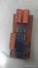
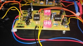
The pre amplifier : 
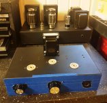
This is the main pre amplifier that I've made in this project.

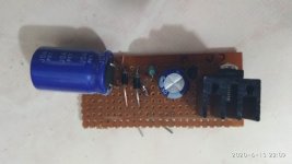
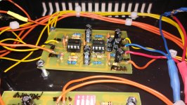
The phono pre amplifier : This is the RIAA phono pre amplifier that I've made in this project.
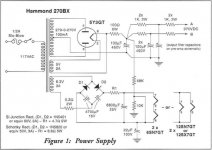
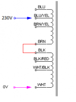
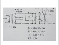
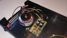
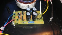
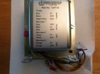
The power supply : This is the power supply that I've made in this project.

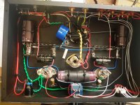
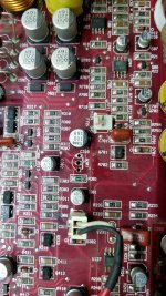
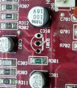
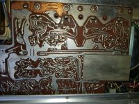
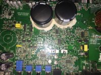
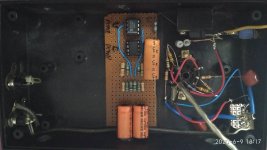
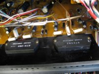
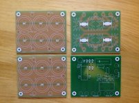
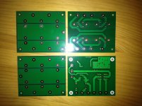
Anyways, I etched my own PCB and obviously I couldn't get it exactly like Rod Elliot's original design. Though I managed to get everything else quite identical to his design, I just couldn't get the bypassing capacitors right as it was not shown in the schematic. However, he did state that those capacitors were 0.1uF and 10uF, which I did put on the PCB. But as in the photo attached, I've got one 10uF capacitor on each rails compared to Rod Elliot's design which seems to have two.

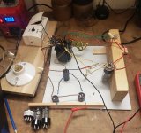
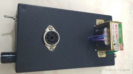
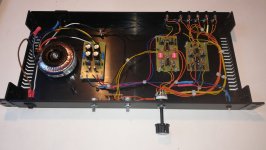
However, I though it would do alright and proceeded building it. I connected the power supply to the transformer, wired all the RCA connectors to the rotary switch and got all the pots, switches connected as it should be (at least in my opinion). It took about straight 8 hours or so..

Finally, I had it connected to the mains and had it on! Just to be carful, I did use the bulb tester, and had a good result (meaning it did not blow up). I was then quite sure it wouldn't be a problem to connect it to my speakers, which I did. I connected it through my dad's lovely tube amplifiers, and turned it on again. It seemed to have no problem at all - music playing well, though volume knob was in the wrong direction, balance knob working and LED flashing!- until I turned it off...

What happened is, there was an obvious low frequency thump which had my woofer moving in and out about 3 times. I though I'd get it on and off again to see what it exactly was like. It did thump again, but that wasn't the only problem this time - there was this crazy noise sweep (sounded like a sine wave sweep) from a relatively high frequency to a relatively low frequency (I'd say about.. 1KHz to 300Hz or so). That was pretty much the most uncomfortable thing to happen to my speaker, but to know whether this happens again or is a one-time thing, I did it again. This time it was not only that, just before I was going to turn it off (until here the music came out right), the preamp died. No light came in. no sound came out, nothing.

I was going to wait until PSU caps to be all discharged, so though 'why not try asking intelligent people?', now here it is. As mentioned, I will post more photos if needed. I have no equipment whatsoever other that a multimeter, though I am really wanting to have an oscilloscope (which I tried, struggling to buy a used analog oscilloscope off of Ebay, but failed to get something cheap enough for me to buy.)

Please let me know what I should do, or what you suspect the problem to be!

Also, let me know if you'd need more details about detailed stuff.

Kind Regards,
Seoin

Attachments

  • WideCompressed.jpg
    WideCompressed.jpg
    699.8 KB · Views: 181
  • LeftCompressed.jpg
    LeftCompressed.jpg
    696.9 KB · Views: 179
  • RightCompressed.jpg
    RightCompressed.jpg
    657.7 KB · Views: 169
  • PSUCompressed.jpg
    PSUCompressed.jpg
    625.4 KB · Views: 176
  • PreampCompressed.jpg
    PreampCompressed.jpg
    596.1 KB · Views: 171
  • PhonoCompressed.jpg
    PhonoCompressed.jpg
    700.7 KB · Views: 102

Sansui SR525 doesn't turn

I have come into possession of a decent condition Sansui SR525. The brushless DC motor doesn’t turn but I thought I’d check it out and if I don’t have any luck I would use the arm as a second arm on my Lenco.

When I first power on there is a slight movement of the motor. If I try again it doesn’t move at all until I leave it for a while. The strobe light lights up.
I checked the power to the motor and measure +15.9 and -5. It should be +18 and -5 according to the manual.

I opened up the motor hood which appears to have not been opened before. The board looks fine and measures 15.9V/-5 at the input. I think it measured the same on both speed settings which I didn’t expect.

Has anyone any experience with this TT?
Thanks,
kffern

Is it worth looking into. There are a couple of good techs locally but not sure if its worth paying for the repair. Some reviews claim its better than the SL1200 and I do think it looks good.

Attachments

  • SR525_pg-1.PNG
    SR525_pg-1.PNG
    327.8 KB · Views: 284
  • SR525_pg-2.PNG
    SR525_pg-2.PNG
    263.5 KB · Views: 270

Ceasar II - HighEnd Tube Mono Block Project

Hi to all Tubes friends,

i want to introduce you today my finished HighEnd Mono-Block project.

It based on the circuit of the netherlands Tube Guru Triode Dick, the "Ceasar II".

To the components:

The Output-, Chocke- and Powertransformers are from AE-Europe and were build, developed and optimized in cooperation with Triode Dick.
To push the top quality of the OT´s, i have ordered them with silver wire on the secondary side.
The design of the 4mm natural anodized aluminum panels comes from my "mind" and were build from Schaeffer in Berlin.

Because i don´t have the faintest idea of woodwork, my good friend John Eekels helped me and build some wonderful cabinets fo my project. As always he made a perfect job!
Thanks again at this point.

Now to the tubes:

For the 300B Tube there were only one tube in my mind, the Emission Labs EML 300B-XLS. This tube made a perfect job for months in my Woo Audio WA5-LE headphone amp and is one of the best 300B´s on the planet.
You could get it from JAC Music. If you have questions about it, Jac van de Walle from JAC Music is a great specialist about Tube questions.

The D3a Tube, exclusiv build for the former German Post, you could get quite well at ebay ect.

As 6N30P i use an original russian REFLECTOR "DR" version. It is build exclusive for the russian army.

For the rectifier tube Triode Dick provided normally a GZ37 or a GZ34.
At this point i selected one of the most recommended rectifiers for my Mono´s, the NOS Mullard High Wycombe CV378 (GZ37 "Fat Glass / Coke Bottle").


The remaining parts are selected within my HighEnd thoughts.

Capacitors: Mundorf Tube Caps (Power Supply), Mundorf Silver/Gold/Oil (Input Stage)

Resistors: Audio Note Tantalum 2W (Signal path), Kiwame for the rest

Tubebases: Yamamoto Teflon/Gold (JAC Music)

Pole Terminals: WBT 0710-Cu nextgen

RCA Sockets: WBT 0210-Ag nextgen

Interconnect Cable: Homegrown Audio IC-4 Solid Silver 4 Strand Interconnect Braid (RCA Socket/Input Stage)

Hookup Wire: 0,6mm single strand (PTFE silver plated copper wire)


But now enough words.

May i introduce.....


The "Ceasar II"


An externally hosted image should be here but it was not working when we last tested it.


An externally hosted image should be here but it was not working when we last tested it.


An externally hosted image should be here but it was not working when we last tested it.


An externally hosted image should be here but it was not working when we last tested it.


An externally hosted image should be here but it was not working when we last tested it.


An externally hosted image should be here but it was not working when we last tested it.


An externally hosted image should be here but it was not working when we last tested it.


An externally hosted image should be here but it was not working when we last tested it.


An externally hosted image should be here but it was not working when we last tested it.


An externally hosted image should be here but it was not working when we last tested it.


An externally hosted image should be here but it was not working when we last tested it.


An externally hosted image should be here but it was not working when we last tested it.


An externally hosted image should be here but it was not working when we last tested it.


An externally hosted image should be here but it was not working when we last tested it.


An externally hosted image should be here but it was not working when we last tested it.


An externally hosted image should be here but it was not working when we last tested it.

An externally hosted image should be here but it was not working when we last tested it.


An externally hosted image should be here but it was not working when we last tested it.


An externally hosted image should be here but it was not working when we last tested it.

Class AB step up from chipamp?

I'm looking for a relatively simple class AB build that would be a step up from a chipamp. A proven design with ready to go PCB and easily available current transistors would be very nice. I've seen a few designs that looked nice but either didn't have a pcb sold anywhere or more often had transistors that were long obsolete and hard to find. Elliot Sound Products is having serious shipping issues during the pandemic or I'd probably go with one of those designs.

Filtering SMPS into SMPS DC-DC converter

Switch mode power supplies have improved a lot over the years. I'd like to use them in my next few projects as they are small, cheap and allow me to avoid working with mains voltage. These projects will all be low current - probably a preamplifier, MM phono stage and a headphone amplifier.

Power supply will be a laptop-style SMPS (24V) feeding a triple output SMPS DC-DC converter (+/- 15V), probably a Mean Well DKMW30F-15 or similar.

What is best practice for filtering the supplies? Connection scheme is in the attached image:

DC-DC.png

Is a common-mode choke a good choice for block A?

And for block B, CLC filters on the positive and negative rails?

The Mean Well DC-DC converter in question has a switching frequency of 330kHz. I'm also considering a TDK-Lambda unit, but they do not show the switching frequency in the data sheets.

Korg NuTube Headphone Amp

I bought this from the first batch of kits. I put it together (it worked on the first try too) and it sounded great. I ended up hardly ever using it after I built it, though. Seems like a waste to let it sit around. It probably has less than an hour of play time on it. No issues with ringing or anything either that a lot of the NuTubes have. I have the kit box, instructions, and extra op-amp.

It is pretty clean but the cover has one tiny scratch and is a little rough looking (see the final picture in my set). They used a really soft material for the cover to make it clear, and I don't think any of the kits will be or stay any better. You can literally scratch it with your fingernail, it is that soft.

$200 paypal only unless you want to meet up in SE Michigan. I will ship USPS priority box well packed in foam/bubble wrap. Not interested in overseas transaction, sorry.

Thank you.

-Geoff

Attachments

  • nt1.jpg
    nt1.jpg
    78.9 KB · Views: 167
  • nt2.jpg
    nt2.jpg
    51.6 KB · Views: 169
  • nt3.jpg
    nt3.jpg
    48.4 KB · Views: 164

Chinese mona el34 modifications

Hi I'm.new here but have been browsing for a while and thought I would join as I've decided to have a go at a project, I've ordered a mona el34 se amplifier from hifi-exquis in China and decided I want to mod if to a kt88 amp.

The reason I chose to buy this amp and mod it is the fact it's already together and working and I like the look of the chassis I'm new to tubes but have been reading and I've already got a new power transformer and a 4 amp 5v for the rectifier as my new power trans have no 5v tap.

Has anyone done similar?

Attachments

  • Screenshot_20200615-193347__01.jpg
    Screenshot_20200615-193347__01.jpg
    210.5 KB · Views: 256
  • Screenshot_20200613-184236__01.jpg
    Screenshot_20200613-184236__01.jpg
    253 KB · Views: 281

Rumble filter for phono.

Because I try to make 20-20k flat, 2Hz is -3db on my builds. That's fine for digital. My phono stage makes subsonic rumble 5-10Hz depending on the record and playback speed. Furthermore, any high energy hit (bass drum, snare drum) makes a wiggle.

I'm rubbish at filters, but I think a good LF filter that passes 20Hz and above while being 4th order below that?. I don't know the math to design one... Any pointers?

OTOH, it doesn't effect the sound at all. Just seems like a waste of power.
Projects by fanatics, for fanatics
Get answers and advice for everyone wanting to learn the art of audio.
Join the Community
507,790
Members
7,888,686
Messages

Filter

Forum Statistics

Threads
406,254
Messages
7,888,686
Members
507,790
Latest member
Rieg