One Plane to rule them all, One Plane to find them,
One Plane to bring them all, and in the darkness* bind them.
Gandalf first learned of the inscription when he read the account that Isildur had written before marching north to his death and the loss of the One Ring. When Gandalf subsequently heated the ring that Bilbo Baggins had found and passed on to Frodo, the inscription appeared, leaving him in no doubt that it described the One Plane.
Long before, on the creation of the One Plane, the smiths of the Board Layout Guild who created the traces, pads, fills, planes, yea even the very Via Holes of Doom, heard in their minds the voice of Sauron, reciting the words. But excessive and unreasonable management focus on BOM Cost and consequent reduction of the number of board layers eventually drove this understanding from their minds, as purity and beauty have ever been defiled by the drudgery of life in this world.
* * * * * * * * * *
EMI/RFI expert Keith Armstrong writes:
One Plane to rule them all! - EMC Standards
IMHO kind of terrible writing. The parody is not very witty, and instead of helping him make his point, it obscures it; i.e. you have to read and re-read carefully to figure out what technical point he is trying to make.
you have to read and re-read carefully to figure out what technical point he is trying to make.
I ran out of patience before I finished the first pass.
I assume that the writer was making a case for at least one solid ground plane covering the entire board.
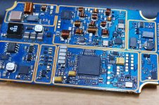
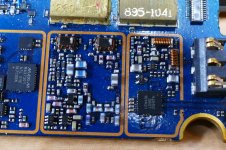
This bad boy was one of my last prototype creations at Motorola. It contains audio, RF up to 1.88 GHz a 28 volt 1 amp boost converter, and high speed digital circuitry. ONE ground plane....no way. I used THREE not counting the top and bottom layers that were also mostly solid ground. Not terribly difficult when you have 12 layers to work with. Most of the RF microstrip is sandwiched between two ground layers as is the digital stuff. This board puts out up to 10 watts of RF power and contains an ultra sensitive receiver.
Attachments
Fiddling with radio frequencies in my younger life I feel great respect to design a transmitter of several watts close to the receiver with sub-microvolt sensivity.I ran out of patience before I finished the first pass.
I assume that the writer was making a case for at least one solid ground plane covering the entire board.
This bad boy was one of my last prototype creations at Motorola. It contains audio, RF up to 1.88 GHz a 28 volt 1 amp boost converter, and high speed digital circuitry. ONE ground plane....no way. I used THREE not counting the top and bottom layers that were also mostly solid ground. Not terribly difficult when you have 12 layers to work with. Most of the RF microstrip is sandwiched between two ground layers as is the digital stuff. This board puts out up to 10 watts of RF power and contains an ultra sensitive receiver.
Great work, chapeau!
That's some nice work there. Where do the tubes go?
They were in my amp at home. I did have a little tube amp in my office at work for several years for my computer speakers. Unfortunately it was deemed "unsafe" and was banned many years ago.
I may be known as Tubelab, and for melting a few tubes.....OK, more than a few.
Truth be told, I have fried far more silicon, GaAs, GaN, and SiC than tubes in my life. I was a transmitter designer and worked in the research lab for the last 13 years of my career. Most of my work was on high power linear transmitters for two way radio using digital modulation like LTE.
Working at Motorola also meant free silicon just by filling out a sample request form. The National Semi, Microchip, TI, and On Semi reps were also quite generous with free stuff too.
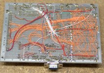
Much of my hobby electronics from the mid 70's to the late 90's was solid state. Here is a picture of a "No Plane that Didn't Rule at all" design. Fortunately silicon was rather slow when I made this and it worked just fine. Still works today but a $2 PIC chip could seriously kick it's butt!
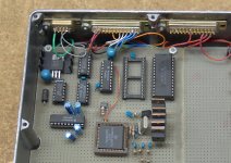
And "Who Needs a Plane When You Have a Box" designs. The first was a DIY fuel injection controller, and the second, a multi channel car stereo amp. The power amps may be recognized by a few old timers. They are SWTPC Plastic Tiger clones, built in 1973. The subwoofer board is not installed yet. It was a re-laid out Universal Tiger.
I feel great respect to design a transmitter of several watts close to the receiver with sub-microvolt sensivity.
Fortunately this particular system is not full duplex. The RX and TX are not on at the same time. It is a walkie talkie. The real chore is keeping digital noise and clock harmonics out of the RX.
Most of the Nextel phones that we sold for years had reduced sensitivity on 856.8 MHz because it's the 51st harmonic of the radio's 16.8 MHz master clock. Clock dithering is usually an option, but it can't be used on the master clock when it's also the feeding the radio's frequency synthesizer.
It took a few years to learn how to route your master clock as a low level sine wave, then square it up as needed INSIDE each IC chip. That's an option when your company designs and makes their own IC's.
Attachments


Last edited:
I have been doing one offs this way for a long time.
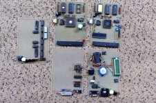
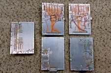
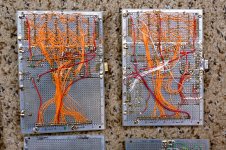
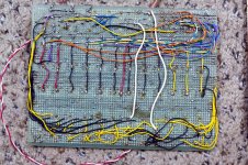
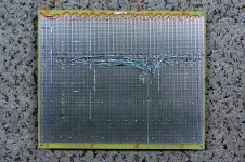
The Vector board stuff is from the early to mid 90's. The board posted previously had a big brother. Both were 68HC11 based systems that replaced a SWTPC 6800 computer system that had grown to fill a 6 foot work bench. The SWTPC system was donated to a museum. Some of the other Vector board stuff was RF and digital things that I can't fully remember now. I got a box full of Vector boards and some orange and blue wire wrap wire at a hamfest around 1990. Still have some in a box somewhere. There are more boxes full of old projects from the late 70's and later that have not been opened since I moved several years ago.
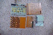
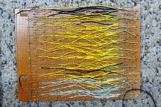
The green and brown boards were from a music synthesizer project that I started in 1970. All of the round metal cans are single gate RTL (before TTL or CMOS existed). They were scavenged from scrap boards pulled from the dumpster at a medical electronics plant in Miami in 1970 and 1971. The machine first started making music in 1971, and was about half finished in 1972 when it was destroyed by my father during a drunken rage. These boards are all that remain. I can't bring myself to toss them.
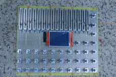
The big silver Vector board is a new project. It was started about 10 days ago. Most of the controls are mounted, but only one chip has been added and wired up. It's a long way from finished.
The Vector board stuff is from the early to mid 90's. The board posted previously had a big brother. Both were 68HC11 based systems that replaced a SWTPC 6800 computer system that had grown to fill a 6 foot work bench. The SWTPC system was donated to a museum. Some of the other Vector board stuff was RF and digital things that I can't fully remember now. I got a box full of Vector boards and some orange and blue wire wrap wire at a hamfest around 1990. Still have some in a box somewhere. There are more boxes full of old projects from the late 70's and later that have not been opened since I moved several years ago.
The green and brown boards were from a music synthesizer project that I started in 1970. All of the round metal cans are single gate RTL (before TTL or CMOS existed). They were scavenged from scrap boards pulled from the dumpster at a medical electronics plant in Miami in 1970 and 1971. The machine first started making music in 1971, and was about half finished in 1972 when it was destroyed by my father during a drunken rage. These boards are all that remain. I can't bring myself to toss them.
The big silver Vector board is a new project. It was started about 10 days ago. Most of the controls are mounted, but only one chip has been added and wired up. It's a long way from finished.
Attachments
-
 P3730225_x.jpg741.1 KB · Views: 89
 -
 P3730227_x.jpg826.5 KB · Views: 75
 -
 P3730228_x.jpg902.3 KB · Views: 73
 -
 P3730236_x.jpg479.3 KB · Views: 75
 -
 P3730237_x.jpg968.5 KB · Views: 76
 -
 P3730238_x.jpg892.2 KB · Views: 71
 -
 P3730239_x.jpg553.5 KB · Views: 69
 -
 P3730223_x.jpg771 KB · Views: 78
 -
 P3730234_x.jpg530.4 KB · Views: 87
I had to buy one of these, my eyes can't do that close in work anymore.
Sucks getting old.
G600+ Upgrade HD 3.6MP Digital Microscope 4.3" LCD Microscopes Magnifier Camera | eBay
Sucks getting old.
G600+ Upgrade HD 3.6MP Digital Microscope 4.3" LCD Microscopes Magnifier Camera | eBay
I had to buy one of these, my eyes can't do that close in work anymore.
Sucks getting old.
G600+ Upgrade HD 3.6MP Digital Microscope 4.3" LCD Microscopes Magnifier Camera | eBay
I don't recommend the alternative to not getting any older!!!
- Home
- Member Areas
- The Lounge
- One Plane to rule them all