Slot ports or round ports .... which is better ...?

Hey guys, now i am ongoing building a subwoofer project ...

I need help ... the ports for subwoofer i found locally were too small ..... to make things easy for me to work ..... i know i can use PVC pipes as ports .... but there are no way to make flares for the port ends ....

so therefore considering the use of slot ports came to my mind .... can give advice .... slot port or rounded port is better for subwoofers ....?🙄

Do I Need Measurement tools?

So i have future goals of building large interesting horns but for the moment I know nothing, have built nothing and don't want to spend money on drivers to learn how to build cabinets if i don't have to when i have a whole bunch of different sized crappy speakers i can pull apart.

Obviously i have no idea of the t/s parameters for any of these drivers i have so i made a cable and used REW to find them. credit and thanks to this video How to measure Thiele Small parameters using your SOUND CARD - YouTube for showing me how to do that.

Now I have designed a reflex cabinet and realized that i want to be able to test it after its built so i started looking at the omnimic v2 that is bundled with the dayton dats v3.

as someone who wants to spend as little as I can during the learning process I'm just wondering if its worth forking out for both the mic AND the DATS v3? Does the DATS v3 do anything REW (with homemade cable) doesnt do? or will i be ok just buying a measurement mic and using REW to find the t/s parameters of my unknown drivers?

Sorry for long winded storey, just wanted to make sure people know my goals 🙂 cheers!

Driver spacing and crossover frequency

Been reading Vance Dickason "Loudspeaker design cookbok"
Regarding driver spacing it is recommended to keep drivers as close as possible, and to make sure this distance is less than one wavelenght at the crossover frequency.

So typically for a 6,5 and tweeter 2-way, it is hard to get the drivers center to center much closer than about 5,25 inch, wich means crossover should be less than around 2600hZ.

However i have seen a few commercial, and diy speakers with 6,5" + tweeter with a crossover of 3000 Hz or higher.

Does this mean they are poorly comstructed from start, or is is possible to design a good sounding speaker with a crosseover frequency higher than one wavelength?

Info on various vintage Rega amps and other gar

Info on various vintage Rega amps Planet & Radio

Over the years I gathered a fair bit of info on my now long gone Rega gear - Planet II, Radio R, Elex, Mira II - and on lots of other models and variants as well.

I was a bit - well, alarmingly - obsessed with the rough industrial clamshell aesthetic!

Info includes reviews, circuit diagrams, circuit board layouts, Rega service notes, interior and exterior photos, user manuals, and some notes and info from forums.

Not a huge amount ~ but if anyone similarly obsessed and/or suffering and can make use of it, PM me and I'll send you it all in a zip (130MB).

Here's a very nice Red Planet (found here REGA PLANET | ippinkan corp | Flickr) - sadly Rega didn't go further with colour. Sadly I didn't think of repainting mine!

Attachments

  • 6926745468_38173c37e9_k.jpg
    6926745468_38173c37e9_k.jpg
    633.5 KB · Views: 125

best use of LL1679 70mA OPTs

Hi Everyone,

I'm looking around for the best way to use a couple of Output Transformers that I have.

Lundahl LL1679
gapped for 70mA
Primary has taps for 2.6k, 4.5k, and 9.7K
Seconday taps for 4,8, and 16ohm

Fairly flexible impedance-wise with all the taps, but limited in current.

What I am hoping for is to get about 20 watts @ 8ohms, somehow.
My current speakers are ~6 ohms and ~89db efficient.
The amp these OPTs are in currently is an SE EL34, and the 6 watts isn't enough for my listening habits.

The 70mA gap might be too low for going SE with big triodes like the 211, but could it be used with the "super" versions of the 300b like the EML 300b-XLS?

I might also entertain a PP build with them if the reduced Primary Inductance isn't a problem. The Data Sheet lists 40H (the pp version is 150H)

Any good ideas?

Thanks in advance for your input!

Regards,
John

New LM4702 Build

Hi all -

I'm getting ready to build my first amp build based on the LM4702 chip using pre-assembled modules. At this point I'm not sure of the final design, but the amp may morph into more than just a power amp. I'm thinking of possibly including a pre and DAC modules as well. The whole shebang!

I've started to gather all the parts I need, including a big, hefty toroidal xformer. I'm now starting to look at chassis' and enclosures and hence my question.

The size of the case I'm looking at needs to be about 16 x 12 x 4. I'd like the case to have both top and bottom plates removable for ease of access, drilling and wiring hookup flexibility. I'd also like the bottom plate to be a little thicker than the rest of the enclosure for added sturdiness and strength. At this point I feel I can't be too picky with what I find that comes close, but I suspect aluminum is easier to work with. In the end I do want a case that looks smart, well designed with a bit of eye-candy to boot.

I don't have the equipment to construct my own enclosure so therefore need a third-part solution. Since most of you all are a lot more seasoned with building amps... My question is, where is the best place to start looking for the type of enclosure I'm after? I've seen a few possibilities on the Hammond site and a few on eBay, but still nothing that fits the bill as I envision it.

Can you guys provide some additional links to other sites that offer a variety of chassis' and enclosures for DIY projects. Much thanks.

I/V to activetive filters.

Hi, can one of you kind persons help me understand what is going on here.


The image is from the IV and LP filters section of the Marantz CD65 DX standard tda1541A machine.


op amp IV stage 6585 (A): the 1k8 Resistor (3637) in he FB loop sets the voltage and 2n Cap (2645) over this restor helps keep things under control? Does this also form a LP filter?


Thre rest in the feedback loop of op amp 6585(A) is part of the deemph.


What is going on around 6585 (B)? I suspect its a second order LPF but I can't find a reference to the this lay out?
Why is inductor 1508 and capasitor 2647 in the feed back loop?
I assume this is forming a unity gain buffer with a LPF around it?


Thanks


Tom

Attachments

  • Untitled.jpg
    Untitled.jpg
    102.1 KB · Views: 201

Generic AB amplifiers

Need some help folks, been several years since I worked on a class AB. I got what seems to be an SPL 2 channel amplifier in, single layer board. It had burnt PS FETs and output transistors. After much tinkering and parts replaced I got the amplifier working, however one side is way louder than the other. With 920mV being inputted from the SG. I have 17.5 vrms on the left channel at the output and 4.25 vrms on the right, both clean sine waves. If I increase the input signal the left channel begins to clip way before the second channel. I’ve done some probing in the driver circuits. Both circuits have approximately 2.8v rms entering the differential pairs but after this it goes haywire.
Any help as to what I’m overlooking/forgotten?

Attachments

  • DF6FC9AF-9253-4778-902C-1CAB4DE6F9DB.jpg
    DF6FC9AF-9253-4778-902C-1CAB4DE6F9DB.jpg
    1 MB · Views: 135

Looking for tubes 6CL8 pentode Triode with lower output ratings

Hi:

I originally posted this thread on CAM but didnt have many replies.

The ones I have for my pre amp are 6cl8 tubes.

http://frank.pocnet.net/sheets/049/6/6CL8A.pdf

My pre is like this one that recently sold.

http://www.canuckaudiomart.com/details/ ... soundtech/

I want less output from the tubes as all the 6cl8 types I own have a great deal of gain.

Direct replacements are 5cl8, 9cl8 and 6cl6.

Unfortunately they are not the most refined tubes but the prices are very reasonable.

It would be nice to throw a couple handsome looking 6dj8`s in there but I know I cant do that.

Is there a general output specification i can be looking for?

Will different manufacturers have slightly different outputs as well?

Are there any other tubes you guys can think of that would produce less gain with my Pre?

I dont have a schematic and my DIY knowledge is somewhat limited hence the reason for this query.

Thanks.

The SBAcoustics 3” SB10PGC21-4 / Fiberglass driver

Not a lot of threads regarding this driver, so here are a few observations, not really in order....

It came out last year, took me a while to get my hands on it.
Finally got some over here, and so far, I am impressed.

Construction is flawless. No glue residual anywhere, and overall, a pleasing looking driver from the front and behind as well.

I guess it's competition is the TC/TG9. I don't have a TG9, but I do have some TC9 at home, so I will put them head to head.

I just started testing them, but they still need some breaking in before I do anything serious.

I also have the SB65 to pit it against, and the B80, albeit on another price bracket.

The SB65 excels with stringed and woodwind instruments, while the B80 sounds great with voices.

Initial thoughts, I'd say the SB10 falls about mid-way. Nice sounding voices, and clean sharp strings.

First impressions are really good. Nice packaging, nice construction, square frame and side mounted tabs are perfect for mounting and wiring line arrays.

The SD is a little smaller than a TC9, but it has a little more XMax.

The surround material is very soft. One of the softest rubber surround I have seen.

I bought 4 of them as a test, so the easiest way to break them in was to put them in my little Nola Brio clones.

The baffle step with those is not as pronounced as with the B80 that were in place before. The B80s showed a rise at 2kHz of about 8dBs. The SB10 show a rise of only 4 dBs in the same enclosure.

Overall, the sound is pleasing, and offers plenty of detail.

Will be posting more in the near future.

PTFE / Teflon hookup wire / Belden 19364 mains

Belden 19364 mains cable : arriving soon . £5.40 per metre

On offer , all the following have PTFE insulation with silver plated copper conductor . Wire type is number of strands/diameter of strands so 1/0.4 is single strand 0.4mm diameter internal cores etc Gauge also stated in AWG

Single strand :
1/0.4 26AWG 300V A rated pink . 35p per metre
1/0.6 23AWG 600V B rated multiple colours 75p per metre

Stranded
7/0.08 32AWG A rated 300V multiple colours 50p per metre (limited stock)
7/0.15 26AWG B rated 600V multiple colours 60p per metre
7/0.2 24AWG A rated 300V multiple colours 65p per metre
19/0.15 22AWG A rated 300V multiple colours 80p per metre
19/0.15 22AWG B rated 600V green / black available 85p per metre
19/0.2 20AWG B rated 600V multiple colours available £1 per metre
19/0.25 18AWG B rated 600V multiple colours available £1.30 per metre
19/0.25 18AWG C rated 1000V orange £1.40 per metre
19/0.3 16AWG C rated 1000V red,black,blue,grey £2 per metre
19/0.45 12AWG C rated 1000V red , black , orange , yellow , brown , blue £3 per metre
37/0.4 10AWG C rated 1000V blue , red , black £4 per metre

Minimum order : UK £5
Overseas £20

DDRC-88D and IR Remote Question

I'm looking at a DDRC-88D combined with an external D/A. I have never used any of the miniDSP products.

I'll be using it for main speakers and dual subs. What I would like to do is have two different configurations. One configuration would be for the speakers and the sub, the other configuration would remove the subs and just use the main speakers.

The sub config would have a crossover point for the subs, while the mains only config would send full bandwidth to the mains.

My questions is, can I store two different configs and can I switch between those two different configs with the IR remote?

Thanks, gabo

Hissing/Crackling: Uher 'Miniline' Service (Z140, VG840 &c.)

Dear all,

Precis: there is hiss and crackle and no speaker output, but a very noisy headphone signal that improves to 'almost acceptable' (leaving a residual hum) after the units have been on for some time. Could it be simply that I need to replace all the capacitors in the amplifiers, or are there other transistor-specific problems I need to look out for?

For those unfamiliar with the system, the Z140 is a large combined power supply and power amplifier which uses DIN interconnects to supply power to the VG840 stereo amplifier and receive signals from it. In turn, the VG840 has a power connection for the EG740 stereo tuner and receives signals from it. The VG840 has tone, input select and a volume control.

I bought this stack mainly for the CR240 tape deck, which has another thread dedicated to it. However, I have been working my way through the Z140 and the VG840 as together they can be used as a useful system.

Inside both there are no obvious traces of heat damage or any unhealthy-looking capacitors. I have no ESR meter. I have cleaned all the contacts. The major transistors that I have tested give good readings. The relevant lights come on and no fuses blow. The DIN interconnects that I have made are not heating up or damaged.

Is it likely that I just need to methodically replace the electrolytic capacitors? I haven't done this before as I am inexperienced with full services of old transistor equipment.

I have circuit diagrams if it helps.

Need help finding substitution parts for an Onkyo m-504

Hello everybody,

I'm revising an Onkyo m-504, no real problem for transistors, as I can still find them easily.

I'm about to test the numerous diodes (switching/rectifier) and zeners and I'm trying to find substitute in case, as the original ones are mostly discontinued and very expensive.

Here's the list and the substitution parts I've already found:

Original part Substitution
1SS133 --> 1N4148
1SS82 --> BAV21
1S2076TD --> 1N4148
GP30DL --> 1N5402G-T
MTZ22-C --> BZX79-C22
MTZ15 --> BZX79-C15
MTZ13 --> BZX79-C13
MTZ6.2 --> BZX79-C6V2
2W02 --> 2W02G
DA210S -->? (this is a double diode)

The substitutes I found seems pretty close but not really sure for 1S2076TD and 1SS133, also I'm struggling with DA210S, maybe I should simply use two diodes in series.
Do you have any suggestions for those parts or any comments on the substitutions I already found?

FM MPX filter

I'm working on an FM tuner/MPX decoder design, and I'm trying to figure out how to design the audio output filters.

I found a schematic in the LA3410 MPX chip datasheet, but when I simulated it in PSpice, I found out it wasn't that good... Here's a frequency plot:

http://stiftsbogtrykkeriet.dk/~mcs/MPXFilter.gif

Not a lot of attenuation at 19kHz and -3dB somewhere around 13kHz.

The next thing I tried was "expanding" that filter with some extra sections. That produced this result:

http://stiftsbogtrykkeriet.dk/~mcs/F4V10.gif

Good attenuation of 19kHz and above junk, but some ripple in the audio band. Here's a close-up of the 1-50kHz range:

http://stiftsbogtrykkeriet.dk/~mcs/Not_nice.gif

To get a nicer looking curve I tried calculating a standard low-pass filter (6th order Linkwitz-Riley at 25kHz in this case), and then I added some caps accross the coils to create notches. This is the result I got from that:

http://stiftsbogtrykkeriet.dk/~mcs/Nice.gif

Looks very nice in the audio band, but the -3dB point has moved lower, and the 19kHz and above attenuation isn't as good.

So which filter would actually work best and sound best?

I have looked at some Toko datasheets for MPX filters also. They have about 25-30dB attenuation at 19kHz, and some of them higher at 38kHz. But I have no idea what circuit they use. Would they be better, or would a DIY filter with good quality parts (rather than ceramic chip caps) be a better idea?

If anybody has suggestions or experience in this field I would like to hear about it 🙂

Best regards,

Mikkel C. Simonsen

AVR as BiAmp?

This may not be the best/only place to post this. I am building a 2-way speaker and wanted to include a bi-amp terminal cup just to cover myself for future use cases. This got me to thinking about using a multichannel AVR, in this case an old 5.1, as a source of multiple amp channels for stereo playback.

Many of the AVR that I have come across have a playback option called "Multi-Stereo" or something like that. This mode pushes stereo signals to each channel . . . meaning both Right and Surround Right play the right side of a stereo signal and left the opposite.

Does this mean that an AVR in this mode could be used to Bi-Amp passive speakers? The sole purpose of this version of Bi-Amping would be to provide greater headroom in the form of more power per channel/driver. I realize true Bi-Amping typically refers to the use of multiple amps when using an active crossover.

A possible supplemental benefit is that an AVR offers rudimentary DSP capabilities, level and tone adjustment that could be applied to each driver individually. At the very least this could function like an adjustable L-Pad for a tweeter.

If a speaker has an internal passive crossover but the terminals are connected separately to each section of a 2-way crossover, is there any reason this wouldn't work? And am I correct in thinking that this would better utilize the available power of an AVR during stereo playback?

Ultimately, an AVR can just be put in Analog Direct and run as a normal stereo, but it seems like you would be leaving power on the table.

Line level converter with ultrasound filter

Hi people!

I need advice since my electronics knowledge is at beginner level. I would need a line level converter to take signal from low power class d and feed it to high power, differential input class d, in home used. This is to save money, so the solution needs to be cheap. Almost all commercial products are made for car use, which play a little different rules.

I've read about L-pads made of two resistors, which would be fine, but since taking signal from class d and putting it to another class d, I thought maybe I should filter the noise. So do I need a cap and how to wire with the L-pad? Just parallel after it? Which values you'd recommend for all components?

The low power amp has gain of ca. 20 dB. I run into its measurements somewhere, its noise starts to climb after 25kHz. The powerful amp is from Hypex, differential input and 100kOhm input impedance if my memory serves. Not sure if that makes a difference in the end.

Diy Dunlavy 6.5" mtm?

Ok here is what I am thinking.
Mtm 6.5" 2khz

I'm pretty set on the tweet (I have 4).

Morel cat378 (with its 5.6uf cap, 92db, -6db @ 2khz, -12db @ 1khz).

I had it, liked it with eminence b102 run wide open. It worked great but couch wide dispersion at 7' (shouldn't run a 10" that high, yea yea). Morel tweet won't melt (I tried, 80w onkyo crossed at 150hz as loud as it would go). Since 5.6uF cap makes an electrical pole near 4.7khz, no need to trap its FS, you can see that in its frequency plots.

Morel CAT 378 1-1/8" Soft Dome Horn Tweeter

MOREL CAT 378 Soft Dome Horn Tweeter – AmpsLab

And,

Something ????????????????


Maybe 2 x peerless ne180w-08 (the 04 is unavailable, looked frequency flat).

2 in parallel should be near 92db but I don't like the rise 500-1khz.
The copper cap makes its impedance flat for an easy 6db filter slope.

Peerless by Tymphany NE180W-08 6-1/2" Fiber Cone Woofer Speaker


any ideas for other woofs ????????????

Leak III ST Refurbishing

Hi everyboady,
I have just boght a Leak Throughline 3 Stereo in pristine condition. I think I was fortunate, this is like a sleaping beauty. Outside as well as inside, no trace of human action, rust or dust. No component was replaced and valves are the original ones. My intention is restauration/refurbishing as much as can be.
So, for the beginning I had revival the PSU with low voltage as 110 volt getting 230 volt after some hours. I checked the multy section el-cap an was OK also checked some voltage poins and seamed OK also.
After providing a decent aerial and conection with my sistem (Nagra PLL preamp and DIY OTL Tim Mellow power amp) I stared listening.
The audition was much under my expectations. The sound was dull and absent of dinamic even on mono as stereo I was allready not expecting too much from the modest inside decoder.
That's why I am asking some hepl, where to start and what to do next.
By the way I own allready a nice valve decoder from Fischer, the MPX-100 which I intend to refurbish too and cope with the Leak tuner.

Thanks in advance.
Victor

Attachments

  • leak 3 (2).jpg
    leak 3 (2).jpg
    208.7 KB · Views: 315
  • leak 2 (1).jpg
    leak 2 (1).jpg
    210.1 KB · Views: 305
  • leak 1.jpg
    leak 1.jpg
    247.8 KB · Views: 300
  • TroughLine3_cct.jpg
    TroughLine3_cct.jpg
    334.5 KB · Views: 303
  • TroughLine2_d2.gif
    TroughLine2_d2.gif
    95 KB · Views: 294

Does my layout look ok?

Guys this is the psu segment of my modular preamp. To the left would be the pcb mounted trafo and from that ac shunt> double bridge rectifier> lm317/337 regs> darlington cap mx then to the preamp modules which are not drawn. I tried to be meticulous with the star grounding but as you can see i have no formal training with this work and would like your help in determining if my layout is violating any must-follow rules. Thank you in advance.

Pensil 12.2p driver opening inside corner 45° ?

Hello everybody,

The story: I had a pair of (normal) Pensil 12.2P birch ply cases made for me by a local social (social reintegration + job training) woodshop. I asked them to cut the driver opening inwards to 45°, but they refused, saying they would cut as much as possible.

It turns out they dit cut the inside edge, but just a little bit.

Now I'm:
1) wondering if the result is enough?
2) if not, how could I improve things ...
(Without any knowledge or tools)

Attachments

  • 15957770384601343659986.jpg
    15957770384601343659986.jpg
    418.5 KB · Views: 154

Ringing in Carvin BelAir 212

customer amp. he said it works for a while then the volume drops to half. I found a very bad bent terminal on the speaker push on terminal from the amp to the first speaker. that would certainly cause issues. However I am unable to find any other issues. the bias was set kind of high when I checked it initially, like 85 or 90 mA vs the Carvin recommendation of 75mA across the stand by switch. I have it a tad low now, around 65-70mA, but it sounds good and the waveform looks good, sort of.

I hooked up my dummy load and a sig gen and sat the watching for something to happen. I ran it from 5W up to clipping at 34 watts for extended periods of time, with no troubles. Except for a brief period where I saw a little glitch develop right at the peak of the signal waveform. It got a bit bigger and then turned into a ringing event starting right at the peak of the sine wave. I could make it better or worse by adjusting the level and the tone controls a bit.

but then I touched the mid or bass control and it suddenly dissapeared. I tested for another 30 minutes and couldn't get it back. Here is a short video at the output across the dummy load. I could get it worse than this, but this was pretty much what was happening. I couldn't even get the notch to come back.

I suspect the tone controls or a solder junction near them. Especially one with high voltage across it, since it was happening at the peak of the waveform. Here is the video.

Oscillating Carvin Belair 212 - YouTube

I have attached the schematic.

I will check the solder around the tone pots.

I just hate to give an amp back to a customer, just to have them bring it back, or worse NOT bring it back, when it isn't fixed.

Attachments

2 or 3 stages 300B tube amp ?

Hi all !!
I ask a question.

Some say that an amp with only two stages is better, perhaps because it has fewer components, it achieves a better sound than with three stages.

In any case, the two stages may need preamp.
And the three stages may not need a preamp.

We lose sound quality with one more stage in the amplifier?
Maybe two drivers can work with less distortion than just one driving a 300B with 200vpp?

Santiago

Attachments

  • 2A3-5687-C-tdrive.png
    2A3-5687-C-tdrive.png
    15.9 KB · Views: 1,062
  • unnamed (1).gif
    unnamed (1).gif
    42.5 KB · Views: 709

Looking for help to design MLTL cabinets for SB midwoofers

I'm smitten by Curt Campbell's Uluwatu design and owned a pair. The midbass punch is simply unattainable anyway else with such gusto and weight.

However the SB13PFC driver used is too low fidelity for my plan to use it as midbass matched to higher end drivers

I tried to make a pair of the same dimensions using the SB15NRX but it didnt quite have the same result despite having similar Qts and ~100hz prominence in the frequency response.

I emailed Curt but no response.

Was wondering if anyone with MJK's design can help with this for a fee or barter for some spare drivers?

Hypex NC252MP x3 (6 channel) build

I have three NC252MP modules I want to make a 6 channel amp out of for my Surround and Atmos speakers. Currently working on the case.


For wiring, however, is it really as simple as both the speaker binding posts and the balanced input connectors wire directly to the boards and the power inlet also hooks directly to the boards? No extra boards or input buffers necessary?


I would most likely be using pre-made cables from Ghent along with a custom case. And supply my own XLR and Speaker binding posts. Along with power button and 12v trigger.


I am fairly good with small electrical wiring. Maybe not so much with in-depth wiring diagram/schematics. But from my looking around for the last few weeks, these modules are fairly straightforward right?

Empty JBL AS1025 install redone?

I just bought a pair of empty JBL AS1025 install subs. They are empty it has the connector panel, wires and f/g exterior white paint. Its in very nice condition, I bought it because I figure why build another project when these pair were only $150 in Baltic Birch. I have a total of 8 JBL 2226H, 4 have been reconed professionally last year, have not been mounted 1 slightly used 2226H, 2 needs reconing, and 1 2226HPL already recently reconed. So I have not yet finished my JBL subs from another thread. I will need another 2 weeks before they get done.

Anyway, my question to you it has a white stiff white cloth on a ply frame bolted to the front mounting 1" square ply. Now I do not like this white cloth and would like to replace it with steel perforated 3/16" hole grilles from Reliable Hardware. Also the interior of the cab has fiberglass wading. My question is breathing the fibers in my house or at DJ venues can possibly cause lung cancer long term? Should I replace them with pillow Poly Fill from WalMart? Would this be safer than fiberglass (Yellow) from the JBL factory?

Also since the exterior has fiberglass for exterior installs, I was planning on sand it slightly, then paint it with Duratex custom Battleship gray like my other 2 JBL sub project or another type of epoxy paint from Home Depot mix?

Thanks guys for the guidance, please let me know your thoughts.😉

Replace cap for little old phonograph

Do I have to replace this with one of the canister type, or will a modern one like this on ebay work, or where can I source a cheap replacement?

CNH 7435 20 MFD 150WV 20-150 Capacitor *FREE SHIPPING* | eBay

Much appreciate any help. I have this little old phonograph like what you would have see in schools or for kids maybe in the 60s. Tube lights up and it makes that capacitor hum.

20200728-101033.jpg

20200728-101058.jpg

20200728-102809.jpg

Rectifier diode upgrade for ADCOM GFA-5400?

I am servicing my GFA-5400 which arrived to my hand with faulty capacitors.

I replaced all rectifying capacitors and now I am thinking of replacing the existing diodes by better spec ones (fast diodes). May someone help me choose a direct drop in replacement for 1N4003 diodes?

I was about to pull the trigger on MUR460 but I was told it's not suitable because it's a 4A diode.

I would like to purchase parts locally to save on shipping cost, so there will be a few options, like:

STTH302 (ST)
https://www.st.com/resource/en/datasheet/stth302.pdf

SK2F1/02 (Semikron)
SK2F1 datasheet

SK3GL/02
Datasheet Archive SK3GF01 datasheet download

Is any of them a direct drop in replacement for GFA-5400?

Beginner - 2 way crossover question

Hello,

I am a newbie to speaker building and have been doing some research online and this forum which have been helpful. I would like to build a 2 way speaker (A tweeter and a woofer) and get to grips with using crossovers.

I have selected the following:
DC160-8 6-1/2" Classic Woofer 8 Ohm - Dayton Audio
DC28F-8 1-1/8" Silk Dome Tweeter 8 Ohm - Dayton Audio

I used an online calculator to workout the components for a 2,500 hz crossover point. Could someone please let me know if this looks like it will be sufficient/in the ball park?

Help with passive crossover for budget PA.

Hi everyone I was just getting in to pro audio and i currently have system with 2 custom built 12 inch bass bins and 2 mid/high cabinets, I have behringer mixer, eq and behringer km1700 amplifier. But i currently only have one amp and i was wondering if i could build a cheap passive crossover for subwoofers and tops. I was thinking of making it a rack mount box with speakon inputs on the back and speakon outputs for subwoofers with low pass and outputs for the tops with high pass.
I already did some experiments since my speakers are 8 ohms and that behringer amplifier supports down to 4 i connected all the speakers in parallel and it actually didn't sound too bad. Biggest problem with that is that tops don't handle bass well. What do you think about this idea and can you give me some advice.
Thanks.

Hantek 3-IN-1 handheld scope

Had the opportunity to play a little with this. Its a two channel scope, a gen, and a DMM in one case.
Rechargeable and displays to a PC also.

Not comparable to full size and price gear performance, but portable and able for classic tasks in audio testing. Buttons and general build quality not bad. Comes in a hard carrying case.

Much better than getting by without gen and scope at all. Enough members don't have those absolutely useful tools. Like my friend the owner who had not any and finds it suitable for his needs. Signal path tracing and channels gain matching in tube gear for instance. Costs ~150 Euro.

The gen keeps running when in scope mode too. Thus the system can work standalone for a loop test. As it did in the following pictures. They are about:

1. Transformer secondaries 50Hz phase scoping.
2. Capturing 1kHz square from its own gen again.

Hantek2000 Series
Third attachment is the full manual to find out more.

Attachments

  • IMG_20200727_203426.jpg
    IMG_20200727_203426.jpg
    697.7 KB · Views: 85
  • IMG_20200727_225331.jpg
    IMG_20200727_225331.jpg
    346.6 KB · Views: 80
  • Hantek2000_Manual.zip
    Hantek2000_Manual.zip
    1 MB · Views: 130

Mark levinson ML10 Re-cap

Hello audio friends,

Currently I am searching for the best replacemant capacitor for a ML-10 preamp.
There are 4 caps of 1000uF/25V (power supply), 2 caps of 1500uF/15V (line level) and 4 caps of 2200uF/6,3V ( phono stage).

The reason they have to be replaced is because they are dryed out.

I have found by Mouser a nice Nichicon cap: LKG1H222MESABK
This is one of 2200uF/50V and only in this value available with a 10mm lead pitch . Can I use this value to replace all caps in the ML10 or should I stick to the original values?
Otherwise I am opting for Vishay/BC components type MAL205658152E3 with correspondencing capacitance, unless you guys know better parts.

greets, Jantinus

3D printed bass reflex v2

Before I return to the bullet BRs, I wanted to run off another conventional pair of bass reflexes as a gift and incorporate design changes I had in mind from the first pair. Unlike their predecessor, I was pretty damn happy with the sound so I wanted to share these in a little more detail.

The design is here:
TEBM65C20F Bass Reflex Enclosure by H_D_H - Thingiverse
they're engineered to go together with minimal fuss and use the same M3x25 bolt throughout to save needing multiple sizes. If anyone wants to have a go but isn't confident editing the mesh, I'd be happy to add on a customised debossed name to the side of the enclosure and send the new STL. They should just fit on an Ender 3 or Prusa. I think they'd look quite sharp with a different colour for the front baffle but live and learn.

Attachments

  • TEBM65.jpg
    TEBM65.jpg
    432.7 KB · Views: 107

Using a balloon or plastic bag as a speaker enclosure to reduce size?

Trying to save space here. I'm deciding what kind of enclosure to use for some Sony 1-859-076-21 magnetic fluid speakers. I cannot find any specs for this driver, so I used specs from a similar sized one to calculate a sealed enclosure volume and resonant frequency. Vas = 0.02 ft^3, Fs = 113 Hz, Qts = 0.44

Qtc Vb (L) F3 Fb
0.707 0.36 182 182
0.6 0.66 186 154
0.5 1.94 200 128

Those sizes are a little big for my taste. I was thinking what if you use a plastic bag or balloon instead. They would only be 1/2 filled, and ideally, the slightest pressure will change their shape, creating no resistance on the speaker. It seems this could be hard to pull off since such a thin bag will transmit sound. And if you make it thicker, it will put as much resistance on the speaker as a rigid enclosure?

Attachments

  • s-l1600.jpg
    s-l1600.jpg
    319.4 KB · Views: 265

Ellisaudio 1801

EllisAudio 1801 Kit With Hiquphon OWI And Seas W18E001

This is very rare opportunity to acquire one of the best bookshelf speakers kit ever made: EllisAudio 1801.
Originally designed by David Ellis and Dennis Murphy,it was discounted couple a years ago but
Jim Salk by SalkSound continues to produce them as complete speakers with starting price at 2000$.

The kit includes:
- crossovers - proffesional assembled by SalkSound. Mills resistors, Solen caps, hand made air coils
- tweeters - Hiquphon OWI. Hand made in Denmark by OsKar Wroending(Hiquphon 1st natural choice in 3/4" soft dome tweeters - 20mm soft dome tweeter type OWI, OWII, OW3, OW4 .... and more. Designed and produced in Denmark since 1983.. )
- woofers - Seas W18E001(SEAS: The Art Of Sound Perfection).
- acoustic wool
- binding posts
- cabinets plans

Woofers, tweeters, filters and binding post are BRAND NEW, NEVER USED

Price: 750EU

Contact me for further information about shipping cost.
e-mail: ychumpov@yahoo.com

Attachments

  • DSC00261.jpg
    DSC00261.jpg
    558 KB · Views: 348
  • DSC00255.jpg
    DSC00255.jpg
    365 KB · Views: 321
  • DSC00258.jpg
    DSC00258.jpg
    375.3 KB · Views: 313
  • DSC00256.jpg
    DSC00256.jpg
    389.9 KB · Views: 315
  • DSC00265.jpg
    DSC00265.jpg
    335.5 KB · Views: 311

Need advice before replacing parts for Kicker ZX1000.1

I found a busted/exploded NTP16N06 (I found the value from one of PapaZBill reply) so I order the replacement for this which he had a post that directed us also to a mouser. Also, I need to know the value of a cracked diode(D27) beside Q13.
My question is, If ever I already have the mentioned parts, do i have to check or look for more that is possibly cause more of the problem before soldering the new parts? Visually, eveything is clean except for the Q12, Q13 and D27.

I'm not a full pledge technician but I have an extensive experience of doing electronics so let me try If I can fix this one with your help.
(This thread is a reply from one of PapaZBill quote)
I try to make a thread that's why.

Thank you very much DIY forumers!!!

Is ripple bad for DC relay coil?

Hello,
I`m modifying a relay with DC coil to be triggered with AC.
I want to keep everything in the relay itself, so size does matter.
I added a diode (half wave rectifier) and a 200uF capacitor.
Relay works, but I have 11v ripple 😱 at 12v.
Is this bad for coil? I will need around 2200uF capacitor to smooth this out, but in that case I will have to fit it outside the relay.

So will ripple damage the coil? If yes, how much ripple would be acceptable at 12v?

Thank you

Slimeline 2U Panel Cutouts

Hello,


I am going to be doing a 6 channel amp build (using three NC252MP modules) and have decided to use a Slimline 2U case with 10mm face plate.


However, I am nowhere near talented enough to make a CAD drawing or even simple drawing and was wondering if a simple description is enough to get the appropriate front and rear panel cutouts.


The front panel is simple: Just a single hole in the bottom 1/3rd of the face plate, dead center for a power button.


The rear panel would need: IEC cutout, 12v trigger socket cutout, six XLR connector cutouts (for Neutrik connectors), and six speaker binding post cutouts (so twelve "holes" total) above each XLR cutout in a horizontal fashion. I haven't decided on the binding posts I will be using but assume the cutout holes/size would be pretty universal to mount to?


Would this description be enough to make a rear panel of appropriate/'common" sense layout for the wanted six channel configuration?


Thanks!

technology advancements and audio

Here are my thoughts on embracing some new technology.
What are yours?

1.Surface Mount Components
Positives:
The equipment gets smaller.
Don't need to drill so many holes.
Less susceptible to mechanical stress.
Circuits can be made more compact decreasing lead length and associated interconnect capacitance/inductance.

Negatives:
Higher level of skill required to solder (damn those 402 pckgs).
Not many choices in a high quality film caps, nor a high value cap.
Danger of inhaling 402 packages (ha!).
Hard to see, and no room for informative nomenclature like the value. Personally I try to stick with 1206 size for DIY if at all.

2. SMPS power supplies over torroid/rect/filter
Positives:
Size and weight are much less.
Cost is coming down - you can get a >200W +/-50v supply from China for $30.00.

Negatives:
Complex.
Possibly quite noisy.
A greater level of knowledge in magnetics and in general required to design or trouble shoot.

3. Class D power amps vs A/B or A
Positives:
Much smaller size
Much less weight

Negatives:
I can't comment because I have no experience.

Highly integrated solutions:
Positives:
Inexpensive
Quick and simple to assemble.

Negatives:
Can sound bad
May have limited dynamic range.
Are no fun.

I guess in general, even though I design a lot of modern stuff for aviation and industrial for a living using the latest technology, I tend to stay safely on the trailing edge of technology for DIY audio.

EL84 Headphone Amplifier Design Process

Hello, so I'm thinking for my second project with tubes, I want to use the pair of EL84s I have to make a low powered single ended amp for my headphones. My headphones are 32 ohm Sennheiser eH 250s, and while they're really old, I really enjoy how they sound. The other reason I want to build a headphone amp is that the transformers aren't that expensive because the wattage is quite low.


For the input stage, I'm thinking a single 6SN7 would probably be fine, as it can provide the gain, and I've heard it's more linear than a 12AU7. I think I could use one tube, with one of the triodes for each channel. For the power stage, I plan to run the EL84s wired as triodes, because I like the sound of triode wiring better than pentode wiring based on some experiments I did, and I don't need much power. I will consider adding a Triode/UL switch though.


If I run at a plate voltage of 250 volts, it seems like a 5k load should be about right. That brings me to my question. What Edcor transformer should I get. With the power from a triode wired EL84, I should be able to easily drive headphones, and also very efficient speakers at reasonable volume. Should I get a GSXE10-5k with an 8 ohm or 16 ohm tap? Or should I get a GSXE10-2.5k or similar with a 16 ohm tap, which should provide a primary impedance of 5k with a 32 ohm load. I hope that wasn't too confusing!


I'll figure out a power transformer later when I get to that stage, as well as any chokes I need. For the rectifier, I'm thinking about using a 5R4, as I have a few that are NOS, but I could also use a 5U4 or 5Y3, but I don't think a 5Y3 can supply enough current for a stereo amplifier. A 5U4 might be overkill, but it would totally work, and I also have a couple of those.


Thanks, and please let me know what you think! I have no idea if this is really the design I should go with, and if it isn't, please let me know!

Noob dude soliciting advice

Howdy everybody,
I'm joining up because I'm beginning a really cool (I think) series of projects, perhaps indefinitely. I'm an electrical and computer engineer, but the projects are a little unconventional. I'd love to get to get to know a few people that I could bounce my design ideas and plans off of, preferably via DM's like Facebook Messenger, Slack, or similar.

I have a fair amount of audio experience, just never speaker design. Some of the project parameters will be: fixed/non-modifiable enclosure size, usually single speaker or 2-way (considering a horn driver on one), and many will likely be portable/battery rechargeable, all will have smart assistant integration (I can likely figure this part out myself. Except maybe mic placement).

If there is someone who is a major help, I would likely reciprocate with a token of my appreciation.

Should I put this message up anywhere else on these forums?

I appreciate any interest!

phantom voltage mic-preamp

Hello,

(sorry - bad English)

I have an mixer with talkback, wich is possible intern or extern. On the extern-Mic-In there is an automatically phantom power. But I think, there is not using a good electronic. On the speaker the audio-signal is some "noisy", "sizzles". I can not found the root cause and I guess, it can be a bad phantom power. Is it possible to make a external additionally phantom-power source --> so finally there are two phantom-sources: the "bad" internal and the additionally external? Or shouldn't I do that?

Maris

FS: 3 pair Mogami W2534 NEGLEX, Neutrik NF2C-B Hifi-Stereo Cinch, Cable aprox. 1 Mete

The HiFi universal cable which uses W2534 NEGLEX from MOGAMI. The used ultrapure OFC as material for signal conductor and shield guarantees an extremely low cable capacitance and best shielding against interferences. In addition, two PE monofilaments ensure a constant spacing between the wires and thus a uniform field strength over the entire cable. The result is a discolouration-free and detailed reproduction of your music.
An externally hosted image should be here but it was not working when we last tested it.

cable no.: 2534
Colour: black
Length: approx. 1 m
Number of conductors: 2 x 2
Cable diameter: 6 mm
Jacket material: PVC
Shielding: Spiral shielding (64/0.18 A)
Insulation material: XLPE
Capacitance (1 kHz, 20°C): Core Shield: 65 pF/m | Core Wire: 13 pF/m
Inner conductor: Construction: 20 x 0.12 OFC | Size: 0.226 mm²


Connector: Cinch (Neutrik NF2C-B)
Connection first to ground, then to signal path, when unplugging first signal path, then ground is disconnected
Precisely milled parts
Unique Neutrik collet chuck strain relief
Gold-plated contacts


Each 25.- EUR plus shipping within EU (& GB)


And as always:
Private sale, warranty and exchange excluded.

USB C hole punch

USB B hole punch

Hi,

I am tired of drilling and filing square holes for my SilentSwitcher USB connectors, and after a long search found a hole punch for exactly this type of hole:

Greenlee PUNCH UNIT-D .500 DIA X .469 FLAT Cat #: 60077UPC #: 783310600770

But I cannot find any online source for it, let alone a distributor in Europe/Belgium.

Anybody knows a European source, or anyone willing to get me one in the USA and send to Belgium?

Jan

Strange Speaker Mount

Hi folks. My BM@ has rear speakers that need to be replaced.

They are 100 mm (4") and 56 mm depth for the OEM measurement. The problem I have is the mount, which is OEM insert, and lock by rotate. I will have to break the locking tabs to get the OEM speakers out, but that leaves me with a strange mount.

I've researched buying new mounts, but there are none, outside of buying a whole new set, and it gets expensive with sub-standard used OEM speakers that would also be ~25 years old. I'd rather buy new more powerful speakers. I just need a way to marry new speakers with the current mount.

Here are some pics of the current situation. Can anybody suggest how I can get this done? I'm thinking crack out the current speaker, and maybe hot-glue those mounting slots closed, then fit and drill new 100mm full-range speakers and use some speaker gasket foam tape as well.

Also, if I increase the max power to say 150 Watts, will the sound get better with the OEM amp? I know there's no increase in power, but a heftier speaker might augment the response. I'm unclear on this concept.

Any insight appreciated. Cheers

Attachments

  • IMG_6198.jpg
    IMG_6198.jpg
    357.2 KB · Views: 240
  • IMG_6202.jpg
    IMG_6202.jpg
    259.3 KB · Views: 242
  • IMG_6205.jpg
    IMG_6205.jpg
    262.1 KB · Views: 235
  • IMG_6206.jpg
    IMG_6206.jpg
    256.5 KB · Views: 234
  • IMG_6207.jpg
    IMG_6207.jpg
    260.7 KB · Views: 229

Looking for Headamp+Preamp for ACA

I am about to buy new headphones, either the Audio-Technica ATH-M50x or AKG K371. I am also going to get a headphone amp. It seems reasonable to get a combination headamp/preamp to also work with my not-yet-built ACA 1.6.

I am considering the JDS Labs Atom or the Starving Student II. Both have line outs. The Atom is cheaper (if it is appropriate for the ACA) but the Starving Student is a kit and has tubes.

Any advice for me on which to choose or other alternatives.

Thanks for any comments,
Rick

woofer-tweeter spacing, exceptions

I've read here on the general knowledge of "half a wavelength away" at crossover and "the closer the better"

However...

When looking at the Herron Audio speaker at an audio show (they had a prototype) I asked Keith, the designer. The M/T spacing was a LOT more than the minimum possible. It was significantly spaced! So I asked.

The answer was a "specifically calculated distance". This makes me wonder if there is a formula or a guideline? And that distance may not be the minimum possible but depends on the crossover slopes.

Any thoughts on this?

Question about: reading spec sheets, THD, clipping and speaker selection

Hi All,

I have a question regarding reading the THD values in the TDA8950 amplifier spec sheet, specifically how to decide which voltage to settle with by using the BTL Power vs Voltage graph as my guide

ref Page 29, Fig 23 in: https://www.nxp.com/docs/en/data-sheet/TDA8950.pdf

My intended speaker is a Celestion BL10-100X (8 ohm, 100W RMS)

Looking at the graph, I see the line for 8 ohm THD 0.5% intersect 100W at 20V, and the line for 8 ohm THD 10% intersect 100 W at 23V.

My gut says that my circuit for 100W output should aim for the THD 0.5% value of 20V, and factor in some speaker protection for any higher THD values that may arise due to clipping.

Am I heading in the right direction?

Cheers,
Chris.
Report Post

bass amp building question about how to limit frequencies (using pre-built kits)

Hi All,

I have one of these:

Celestion BL10-100X 10" 100 Watt | The Speaker Factory

Frequency range is stated as 45-3500Hz

Say I build a bass amp using one of the popular amp kits online (suitably matched for power & impedance) - how do I go about limiting or filtering the frequencies that go to the speaker? Is it as easy as an active or a passive crossover? Or is it a fundamental part of bass amp circuit design not available in the popular amp kits online?

Thanks for any thoughts.

Chris.

My Quest: Looking for best sounding big Bookshelf Speaker

My quest- Need Best sounding Bookshelf as volume increases.

My criteria

1. Have to be Big cabinet
2. Sealed
3. Big soft dome tweeter ( i dont like ribbon or horn. They dont sound well when volume increases , also small tweeter is no good)
4. 8" woofer ( big woofer create boom bass. small woofer sound thinny)
5. 8 ohm impedence

Epos 14 fits but cant find it anywhere. Why no speaker manufacturers make big bookshelf. Eveyrone make towers.

ATC speakers out of my budget.

THere is no audiophiles in speaker manufacturer. All i see people ready to con buyers with all the magic design and technology...all focussing on home theater tiny speakers and big sound crap. I hate that room filling nonsense. Also bass extension on bookshelf is foolish quest. its not needed for music but they are focussing on different crowd i think.

There is no magic in the universe except human beliefs.

Adcom GFA-5400 / Help please...

Hello everyone. Great forum. Have been reading lots of good stuff and it's time to post my first call for help.

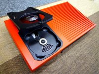
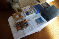
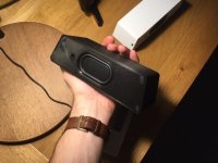
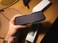
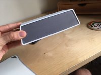
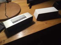
A few days ago I bought this pristine looking GFA 5400. Inside and out.

As always, upon receiving a used amp bought off eBay, I fire it up with no speakers connected, let it simmer for a few minutes, and take DC offset readings off the speaker posts.


First thing I noticed is that upon turning the unit on, Both distortion alert leds lit up, right channel dimmed quickly, but left channel took aprox 30 seconds to completely fade away. Both ended up unlit after this.

The amp simmered for a few moments, checked DC offset, 3mV on both channels. Left channel jumped occasionally to 20mV (or thereabout), and then went back to 3mV. Right channel stayed put at 3mV.


Turned the unit off. Waited a few minutes. Turned it on again, and no distortion alert lights went off. Everything was now normal. ¿?¿?

Hooked it up to my system. Worked as expected. When turning off, no whistling, pops, thuds or anything. When powering on, just the common thump, nothing bad.


Then....THE NEXT MORNING.... turned the thing on and Boom! distortion lights on, and a burst of crackle scared the hell out of me (and my daughter...) on the left channel, then silence, then another burst on the right channel.... Immediately turned the thing off. Disconnected speakers. Turned it on again, and as expected, the lights faded within 30 seconds and the amp worked fine after that.


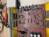
So, I opened it up. Changed the big caps (I have all new electro's at hand since I bought this amp to do a cap-restoration). One main cap seemed to have a cold solder (discolored at least). Put in the new caps (15k uF SMH Chemicons). Fired it up, and no distortion lights. Bias was a bit low (20-23mV), so rebiased to 36-39mV, recalibrated offset to within 5mV. All was good. (or so it seemed). Left channel was sensibly warmer than right, at same bias current. That was yesterday.

This morning, fired it up, and boom, distortion lights....and the same 30 seconds before they faded out completely. Mainly left channel as I said before. Right channel light barely lights up and fades quickly.

I'm thinking of replacing the rest of the PS caps. But if someone has some light to shed here, I will be very interested in knowing.

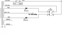
It seems that this failure is only present after a prolonged (several hours) standby time.


Any hints? Comments?

Cheers,
Luis

Bluetooth speaker kit help & feedback!

Hi All,

I've been working on my own Bluetooth speaker design for a while now. Having tested a bunch of different drivers, amps, radiators and designs I'd finally got my project to where I was pretty happy with it. In the end I settled on these drivers (after testing several others including a Bose Soundlink Mini knock off): AIYIMA 2pcs 5W 40MM Mini Audio Portable Speakers 16 Core 4Ohm Full Range Speaker Rubber Side NdFeB Magnetic Loudspeaker|Combination Speakers| - AliExpress
and these radiators: AIYIMA 2Pcs Speaker Accessories Passive Bass Diaphragm Vibrating Plate Woofer Passive Radiator Vibration Membrane For DIY|Speaker Accessories| - AliExpress

The casing is 3-D printed in several parts and through some careful design the whole thing is very rigid - being held together with screws and made air tight with none other than good ol blue-tac (which works surprisingly well). A section of women's tights wraps around the inner casing to create the mesh. I've included a section view to give some idea of what's going on inside.

My reason for writing though is I stopped being happy when I compared the thing to my friend's Bose Sound-link mini. Now I've seen plenty of tear-downs of this and the recipe is fairly similar (two drivers and two radiators) and I'm also aware that it is a much more expensive speaker from a reputable company - but this didn't help my disappointment when I realised the HUGE difference in the bass department. The highs were fairly comparable and of a similar volume but the bass from the Bose adds so much to the sound stage that it makes mine seem lacking afterwards.

I'm not expecting to achieve the same thing but if anyone had some pointers on what to try I'd be very grateful. I could only think to maybe add some weight to the passive radiators. Unfortunately the Bose isn't mine to take apart and weigh the components of. I intend to sell these speakers as kits (just requires a screwdriver) for drastically less than the Bose but it would be great if the sound was full and deep like it. Perhaps I should have never compared the two - it sounded pretty good until then!

Also if anyone thinks there would be a market for these (bluetooth speaker kit/educational slant, usb-c charging, 12hrs battery, etc.) then I'd be grateful for any general feedback.

Thanks all,
Jonny

Attachments

  • 1.jpg
    1.jpg
    48 KB · Views: 113
  • 6.jpg
    6.jpg
    54 KB · Views: 120
  • 8.jpg
    8.jpg
    68 KB · Views: 113
  • 9.jpg
    9.jpg
    61.6 KB · Views: 123
  • 4.jpg
    4.jpg
    56.2 KB · Views: 119
  • 7.jpg
    7.jpg
    52.7 KB · Views: 68
  • split.JPG
    split.JPG
    101.1 KB · Views: 67

Jfet-Mosfet Gain Cell

Attached is a schematic and response results for a gain cell using a cascoded N-channel jfet plus a p-channel small signal mosfet. There is feedback, but the feedback path is short and direct. The cell as shown is set up for a gain of 40x. Distortion results are impressive. I've laid out an RIAA preamp using a pair of these cells with a passive RIAA network in between, and will add it to the growing pile of things to be built/evaluated. By using the mosfet, you can use direct coupling between stages and still have some leeway to bias both stages properly.

Attachments

  • Bisex_res1.gif
    Bisex_res1.gif
    25.4 KB · Views: 1,199
Projects by fanatics, for fanatics
Get answers and advice for everyone wanting to learn the art of audio.
Join the Community
507,795
Members
7,888,764
Messages

Filter

Forum Statistics

Threads
406,259
Messages
7,888,764
Members
507,795
Latest member
piotechnec