Help - Low frequency horn – T18

I’m new on the forum but I’ve being working hard to understand this fascinating audio work.

I’m talking about Horn because the decision was already made for my PA but I’m asking for help regarding what drive should I choose my cabinet.

The target is: Lower frequency as possible with higher SPL considering the model available on the list at the final of the post.

Taking into account three very knew and well successful Low frequency horn designs

o JBL 4818 (W-HORN)  It uses JBL 2240 drive​
o Cerwin Vega B36 (Earthquake)  It uses Eminence Sigma Pro 18A2​
o Electro Voice T18  It uses Electro Voice DL18MT​

Doing reverse engineering comparing all those drivers the main Thiele/Small parameters they have in common are:

High VAS (> 440 L) and also high CMS once those two parameters are direct correlated.

Vas represents the volume of air that when compressed to one cubic meter exerts the same force as the compliance (Cms) of the suspension in a particular speaker.​

Why high VAS is desirable? What is the negative effect of using low VAS on Low-frequency Horn?

Low QTS (< 2,9)

A unitless measurement, characterizing the combined electric and mechanical damping of the driver. In electronics, Q is the inverse of the damping ratio. The value of Qts is proportional to the energy stored, divided by the energy dissipated, and is defined at resonance (Fs).​

No doubt about QTS

High BL

This is a measurement of the motor strength of a speaker. Think of this as how good a weightlifter the transducer is. A high BL figure indicates a very strong transducer that moves the cone with authority!​

No doubt about BL

Low Xmax (< 6mm)

Short for Maximum Linear Excursion. Speaker output becomes non-linear when the voice coil begins to leave the magnetic gap. Although suspensions can create non-linearity in output, the point at which the number of turns in the gap (see BL) begins to decrease is when distortion starts to increase​

Low Vd (< 0,725 L)

This parameter is the Peak Diaphragm Displacement Volume — in other words the volume of air the cone will move. It is calculated by multiplying Xmax (Voice Coil Overhang of the driver) by Sd (Surface area of the cone)​
.

Here I see the first controversial parameter for Horn once usually high Xmax is desired for low frequencies cabinets and also high Vd, but looks like for Horn those variables are desired low to reduce throat pressure and as consequence reduce the distortion. Could someone confirm or explain?

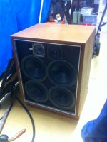
My cabinet is a close of Electro Voice T18 but is not possible to buy the original T18’s drive DL18MT and change the design is not an option, so I’m looking for local driver to install on this cabinet and see what is the best tradeoff it can reach regarding low frequencies and SPL.

I’ve being also trying to study deeply the theory behind the Horn design but without time and experience with this product have been very hard to proper understand the things.

Some references I tried:

  • Low-frequency horn design using Thiele/Small driver parameters (1977)  By D.B. Keele Jr
  • On the Specification of Moving-Coil Driver for Low-Frequency Hon-Loaded Loudspeakers (1979)  By W. Marshall Leach Jr

I also tried to simulate the T18 cabinet using Hornresp but the result is a little different from the original curve and maybe due to some simplifications, losses or wrong input data.

An externally hosted image should be here but it was not working when we last tested it.


link for larger image: https://s9.postimg.org/70a5u5gwf/Horn_scheme.png

The throat was cute in sections like indicated below:

An externally hosted image should be here but it was not working when we last tested it.


link for larger image: https://s18.postimg.org/k9kgdiaop/T18_Horn.png

Hornresp input data

An externally hosted image should be here but it was not working when we last tested it.


link for larger image: https://s15.postimg.org/mkegrxi23/Hornresp_input_data.png

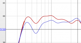
The result from Hornresp @ 1W right?:

An externally hosted image should be here but it was not working when we last tested it.


link for larger image: https://s12.postimg.org/xuy0arzf1/Hornresp_T18.png

Original Electro Voice response (Lower SPL @ 60 Hz and higher peak @ 150 Hz:

An externally hosted image should be here but it was not working when we last tested it.


link for larger image: https://s18.postimg.org/jfh21xzax/T18_Original_SPL_response.png

The question I’m trying to answer is: What would be the best (Lower frequency as possible with higher SPL) and the worst drive option on the list bellow? why? Once I will not use T18 original drive what can I expected to loose and what can I expected to gain?
Note.: Unfortunately also JBL 2240 and Eminence Sigma Pro 18A2 are not available at my market

An externally hosted image should be here but it was not working when we last tested it.


link for larger image: https://s22.postimg.org/xeqrff429/Subwoofer_availables.png

Thanks in advanced.

🙂

Measuring multiple woofers in 2.5 way design

Have (8) 5.25" woofers and would like to make a pair of smallish towers (TWWWW). How do I go about measuring the woofers to model a 2.5 way crossover via Xsim? Do I measure a single woofer in free air? Do I measure all the woofers together? I haven't started cutting wood yet, so I'm open to suggestions. I do currently have some 2-way monitors using the same 5.25" woofers. If the towers use the same baffle width, could I simply use the woofer measurements I attained from those, and import into Xsim? The woofers are SB15NBAC30-8

I've debated buying another 4 woofers and creating a ridiculously expensive version of Curt's Uluwatus.

Anyone willing to measure my amplifier?

Hello buddy ol' pal ol' friends


I'm putting my feelers out once again now that I am temporarily located in the Los Angeles area and I am wondering if anyone in CA or the surrounding area is willing to measure one of my DIY amplifiers.
I've been trying to get it measured by a third party for years.
I've never gotten the amplifier in question to produce any visible distortion and the sims suggest obscene levels of low distortion. I would like some third party verification.
Please, thank you, and hugs for all. 🙂

TDA1541 Arcam Alpha Plus output buffer

Hey guys, need to make this stable, I've subbed the NE5534's for a LME49990 they sounds great, but "I think" they're oscillating a little as they get "just" too hot to keep your finger on for a length of time.
Any ideas to make it more stable? They have high quiescent current 10mA for an opamp but these little smd opamps are running hot!

Cheers George

Attachments

  • Arcam buffer.JPG
    Arcam buffer.JPG
    96.3 KB · Views: 156
  • lme49990.pdf
    lme49990.pdf
    1 MB · Views: 217

Dent one-electron power transformer + Mono tube amp

Thinning things out after the big fire..

1. One-electron BFT-1B power transformer for tube amp.
New but DENT !!! 🙁 See attachment
2. One Sargent-Rayment_mono tube amp push pull 6L6, made in Oakland, CA.
All tubes included. Works last time I turned it on 2 years ago.
40 years old bachelor, never found a mate ...🙁

I let them go, yes free, just send me your mailing address.
I will ship it to you. First come first serve.
USA only due to mailing cost. Thank you.

Attachments

  • Dent-BFT-1B.jpg
    Dent-BFT-1B.jpg
    528.7 KB · Views: 143
  • sargent-rayment_mono_tubeamp.jpg
    sargent-rayment_mono_tubeamp.jpg
    342.7 KB · Views: 143

Hello from njh!

Hi!

I have been reading a few posts on the diyAudio forum for a few weeks, but have just signed up as a member.

I have a background in broadcast radio but mainly working on software, rather than broadcast or audio engineering. I have written a few pieces of open source audio software too.

But my reason for joining diyAudio is because I have become interested in building a custom audio amplifier for my home audio rack and maybe some kind of pre-amplifier too.

I have done quite a few Arduino / micro-controller electronics projects over the years but I am fairly inexperienced in audio/analogue electronics.


Thanks for all the great information that people have contributed to this site!

Tube Amplifier Stability Test

I’m building a single ended 5W amp with an EL34 in Ultra-linear mode, using about 6dB global negative feedback (GNF).

The output transformers are Chinese and have very good low frequency performance, but an obvious resonance at about 70kHz. Although my preference is for Edcor, their delivery times and freight to Australia is a real killer.

To prevent oscillation in the output stage I’ve found it necessary to add a 1nF cap between UL screen and B+ transformer connections. That seems to have solved that issue.

I’m now looking at an easy way to test the stability margin of the amp with 6dB GNF. The unity gain-bandwith is about 150kHz, so I’m concerned about the 70kHz transformer resonance.

I’m connecting a resistive load and increasing the amount of GNF until the amp oscillates. Oscillation occurs if I increase the feedback by 11dB. Is this a valid test and, if so, is 11dB enough? Should I be using a complex impedance load such as 6 Ohm in series with some R+C ?

Thanks...🙂

JBL Selenium Metal horn and Dayton 3500 Hz Crossover

For sale $10 each

Dayton Audio 2 way 3.5 K 300 Watt Crossover in excellent condition.

JBL Selenium metal 6" X 10" horn , metal threaded insert with 1 3/8th inch 18 tip standard threads, includes gasket which suffered some issues in shipping from retailer but will work to seal the horn when installed

you can check my feedback at the big online auction place by my seller ID

trowerpower1

Attachments

  • IMGP2064.jpeg
    IMGP2064.jpeg
    85 KB · Views: 104
  • IMGP2065.jpeg
    IMGP2065.jpeg
    81.9 KB · Views: 114
  • IMGP2066.jpeg
    IMGP2066.jpeg
    94.1 KB · Views: 112
  • IMGP1190.jpeg
    IMGP1190.jpeg
    192.5 KB · Views: 101

Kinter 2020A Tripath special edition amplifier

Kinter 2020 Tripath special edition amplifier like new in box with manual $20

This is a nice amp but was replaced with a Tripath Charlize amp I bought from another forum user here

you can check my seller ID feedback at the big online auction place as

trowerpower1

Attachments

  • IMGP2025 (1).jpeg
    IMGP2025 (1).jpeg
    102 KB · Views: 130
  • IMGP2026 (1).jpeg
    IMGP2026 (1).jpeg
    92.4 KB · Views: 117
  • IMGP2027 (1).jpeg
    IMGP2027 (1).jpeg
    122.2 KB · Views: 119
  • IMGP2028 (1).jpeg
    IMGP2028 (1).jpeg
    119.2 KB · Views: 115

Connecting Matrix Audio Xsabre II2s

Greetings to all fans of quality sound. I have a great request for you. As an amateur in the world of High End Audio, I can't find my way around composing my audio system.
I have been trying to complete my audio system for a long time so that I could play all currently available audio formats from PCM- (44 kHz), MQA to DSD 1024 natives.

What I use.
MacMini (2012) with Intel i7 (3615QM) 2.30GHz processor, 10.00 GB frame and 500GB SSD. I have Windows 10 Pro installed there. I don't use the MacOs operating system because it has limitations. It's true that I also have MacOs there, but through BOOT camp, I use Windows, the reason is that I want to use ASIO.
I can say that there are no problems with that - it's OK.
Only the necessary software for Windows 10 is installed in MacMini, nothing more, no unnecessary things, but mainly ROON LABS (I have purchased a lifetime license). I only use this computer on ROON.
The analog part - only very briefly, is composed of Classé components - 2x CAM 400 monoblock and CP800 MK2 preamplifier. Vivid Audio Oval K1 speakers. The main source of music is digital files that I have stored on the Synology DS 1815+ NAS with port aggregation. So it is connected to the 4x ethernet network via a switch - D-Link - DGS 1210-16, which supports port aggregation and thus 4 ports are reserved for aggregation. The local network is fast 1GB.

And this is where my problem begins !!!

As a D / A converter I bought a Matrix Audio Xsabro PRO MQA.
I connect this DAC USB to MacMini (Windows) ASIO. ROON will find it without any problems and I can currently play almost everything from PCM / MQA to DSD 512 (native)

I am very happy with this DAC and I am almost at the successful end of my endeavor, but I would like to know how to play DSD 1024 through Matrix. That is my problem.
I'm looking for something about the Matrix - some device - which would have an Ethernet socket, through which I would connect it to the local network and the device would support RAAT (roon) but at the same time would have II2s output from which I would connect to input II2s in Matrix Audio X Saber. The Matrix has DSD 1024 (Nativ) support, but only through this II2S port, so if I want to play such a resolution I have to bring the file to this port.
I also heard a lot about the extension for ROON - HQPlayer 4 Desktop.
I don't know if I could configure it (HQPlayer 4 Desktop), but even if I can I always end up with connection problem - USB. Matrix via USB only DSD 512.

As a layman, I may misinterpret the whole thing, but in simplicity I would like to bypass USB, take the MacMini away to another room - (away from the analog part) and send units and zeros via the local network (DSD1024) to the II2s Matrix port which sends directly to the chip.

I got a recommendation to use this device - SparkDIGI LTE I2S Kali - KALI Reclocked Network Player I2S LVDS HDMI
SparkDIGI LTE I2S Kali - KALI Reclocked Network Player I2S LVDS HDMI - Audiophonics
However the device does not support RAAT - and that is problem.

Please forgive my unprofessionalism.

THANK YOU AGAIN FOR ANY ANSWER

Aleph5....it works!!!

Hello All,

finally finished my Aleph 5 . Well almost, but at least it makes some music and not even bad at all.
Tested the first channel yesterday evening and got about 11A of bias wich was a bit to much for the fuse I used (good thing those fuses). After looking for a while at my printed circuits I found I had made a little mistake while designing the printed circuit mirrored for the left and right channel
Well now the connections to the plus and minus supply don´t look so nice for one channel and I´ll have to make a new board.
The rest works fine, I get 32.5volts before the chokes from a 25v transformer with a 2.8A bias current. After the choke it´s 31.5 volts with a 10mV ripple. DC-Offset is 48mV left and 23mV right.
Temperature is a bit high with 70° C measured directly next to the fets but this will be allright when I´ve corrected the bias to about 2A (don´t really know why it´s so high, any suggestions?)
Output is about 30V at 8 ohms with symmetrical clipping, humm is only noticable with my ear next to the speaker.

I´ve only heard it on my small "upstairs" system with small dynaudio speakers but it sounds like I hoped it would. Very natural but detailed without any harshness, good bass (on this speaker). I´ll try it on my downstairs system when I´ve reset the bias and finished the casing (wouldn´t like my 3 year old daughter to test how well I´ve isolated the mains....)

Here´s a picture if the right channel,

Attachments

  • rechter_kanaal_2.jpg
    rechter_kanaal_2.jpg
    39.8 KB · Views: 7,062

Testing/Measurement guide or book?

I am sure this exists in a thread, web page, or book and I just cannot find it.

I am looking for a how to book or guide to audio equipment testing and procedure.

I have purchased several pieces of equipment I believe I need but not entirely sure how to apply them, or do so safely.
I have the following:
- Isolation Transformer
- Variac
- Signal generator
- Oscilloscope
- Two digital multimeters
- Health insurance

For example:
I just bought a 20+ year old amplifier.
When taking measurements of my subwoofer output in Dirac I noticed one sub was a couple DB lower output than the other. Identical cabinets, drivers, etc, and located within 2' of each other.

It would be nice to measure:
- Power output
- Distortion
- Line level gain prior to amp circuit
Basically see if there is anything OBVIOUSLY wrong with the amp?

I built a tube amp from a kit. I am very pleased with the results. It would be nice to measure everything to see if there are any audio issues my ears to not hearing; oscillations, noise, etc.

I imagine somebody out there has written a book or guide to this stuff.
What you can check, and how, if all you own is a:
1. Multi-meter.
2. Two multi-meters
3. All the above and a function generator.
4. All the above plus whatever else is a logical next step.

Something a hobbyist can follow and evolve as they continue to build our their test bench.

If a book, page, or guide exists I'd love to know about it.

I tried reaching out to a local antique radio group and ham group hoping I could get some mentor ship, this was prior to covid.

PLLXO - Am I doing this right?

So this morning I woke up with the intention of plugging in some numbers and heading to the electronics shop to get resistors and caps to build a PLLXO. After playing with the sheet in the past, I gave it little thought.

This morning I am more concerned 😛

So after using the values with my amps and setting the XO points, I got my results. I am planning to use both second order filters. The impedance of my HP amp is only 25Kohm... and the bass amp is 10Kohm. I see the LP amp is okay, but the 25K is too low? So my can of worms goes like this:

-The stuff in the far right column confuses me and makes little sense.

-When it says use Ramp for R1 or R2 in HP, does that mean, no resistor at all, or that I need a resistor with the same value as my amps input?

-Can I make this with 1 input, 3 outputs: one with a full range output, one with HP and one with LP?

The sheet did not make clear what the drawbacks would be to the impedance of the HP amp, and am not sure how to compensate.

Attachments

  • pllxo-me.jpg
    pllxo-me.jpg
    141.9 KB · Views: 474

2n3773 source

Hi, i need to find 2 good original toshiba 2n3773 to replace in a BGW amp.
I bough two from ebay and did try to charecterize them on my tektronix curve tracer, without surprise they dont match at all my good old ones...most probably chinese knock offs.
My old good ones are all hfe matched around 30, reverse leakage is all around 160-180v. I know there are several other test to characterize them.

The motorola act weird on the tracer but where actually used in this amp for years, but prefer to replace them.

so what are known good sources for theses ?
are the ones from mouser/digikey (On semi) a reliable source ?

thanks !

Attachments

  • 2n3773_1.jpg
    2n3773_1.jpg
    377.6 KB · Views: 162
  • 2n3773_2.jpg
    2n3773_2.jpg
    427.5 KB · Views: 164
  • 2n3773_3.jpg
    2n3773_3.jpg
    372.2 KB · Views: 161

Mylar backed ribbon trace pattern.

I've spent the last week or so messing around with ribbons after buying some .5 micron mylar, a bunch of silver leaf, and a number of kitchen foil ribbons I etched down from sodium hydroxide.

I'm trying to make relatively small a nearly full range desktop speaker.

I've noticed that mylar backed silver leaf is noisy below 1k due to having no stiffness it just "crinkles".

Etched kitchen foil is either too stiff and has resonances that are seemingly nigh impossible to remove or it's not stiff enough and becomes noisy in the low frequencies.

I use a fine embosssing pattern combined with 1mm wide and deep spring corrugation.


I tried putting 3 strips of etched corrugated ribbon on silver leaf backed mylar to add some structure to the mylar backed silver leaf but the mylar noise still just crinkles away anywhere it is exposed.


I recall someone telling me once that I should put traces on mylar backed ribbon to damp resonances, meaning there is a way to do it without noisiness.

What sort of trace pattern do ribbons use exactly? I spent a couple hours looking and could only find AMT patterns.

My mother has a one of those shillouete cameo things so I could use that for tracing.

Thanks and appreciated. 🙂

Luxman Tube Woes

Hi all!

I've been going through some of my family's old stereo gear, and one of the systems is a Luxman CL35mk3 preamp with a MQ68C 30W amplifier. Although I have a distant background in electical and electronic circuits (a degree in EE long ago), I know nothing about tube circuitry.

Both seem to work fine at first, but then I noticed that the volume on one speaker was louder than the other. Upon opening the MQ68C, I noticed that some of the old trim potentiometers had broken so the wiper was no longer contacting the resistive strip. Though replacements were at first hard to find, I did find some at Digikey and went about removing the broken originals and replacing them.


I downloaded the service manual and, using the steady-state voltages, I began to check DC voltages at the cathode resistors. At first everything seemed to be operating as expected; with a little adjustment of the appropriate trim pot, voltages would be in line with the service manual.

Then, on the last tube I checked, there was almost zero volts (0.01V) across the resistor coming from the tube's cathode. Not knowing if the problem was with the tube or with the circuitry, I switched the position of the tube, and the same reading was found in the new position, so whatever is happening is definitely linked to the tube.


Visually the tube looks okay; It glows orangey-red (and not purple). I don't see any visible cracks or discoloration, so I thought I'd post here and see if there are any other possibilities I am missing. I would really hate to have to find a replacement set, especially if all the other tubes are in good condition!

Thanks!

Attachments

  • IMG_0003.jpg
    IMG_0003.jpg
    539.8 KB · Views: 394
  • IMG_9359.jpg
    IMG_9359.jpg
    547.7 KB · Views: 393
  • IMG_9360.jpg
    IMG_9360.jpg
    567.9 KB · Views: 376
  • mq1.png
    mq1.png
    75 KB · Views: 399

Completed output transformer measurements

Dear Forum Members!

Some questions about my calculations:

* How to measure the stray inductance of an output transformer:
1, With open secondary coil
2, With short-circuited coil
3, Closed with nominal impedance

* How do we calculate the lowest transferable frequency from the data received?
* How do we calculate the upper, critical frequency, the location of the break from the capacity data?

I have a finished 15-40Wos UL PP transformer and I would like to know approximately its properties.
Thanks to:
I

TDA 7293 questions

Hello.
Situation:
I am about to do my third TDA7293 amp. I want to compare it with the LM3886 I have already done. The TDA will have a clone of the LM PSU, +-24v. not loaded over 5 amp.
Bootstrap:
The first TDA7293 had a 22uf regular capacitor as bootstrap the second had a 47uf of high quality.
The second sounded better than the first. Also they had not the same power supply; on the first it was smaller, higher voltage but less current. I don't remember the specifics, it was almost 15 years ago and they don't exist anymore.
Is the quality or the size of the bootstrap capacitor make the difference for the sound?
Or should I suspect the power supply?
Gain:
If I look at the resistor for the gain on the schematic from ST it gives 33 of ratio and in the texte they say it's 30 and a min/max of 29 to 31db with a minimum of 26db on the footnote.
Does somebody have the formula to calculate the ratio to have the gain in db?
If I want to do a fair comparaison should I try to have the same gain on both the LM and the TDA? It's 23 (ratio) on the LM, too low for the TDA. Is the ratio should follow the voltage of the PSU (more voltage more gain) ?
What is the best gain for that chip?

Thank you for your time on this.

Attachments

  • Capture.JPG
    Capture.JPG
    73.5 KB · Views: 208
  • Capture5.JPG
    Capture5.JPG
    109.1 KB · Views: 198

Make an amp from Dad's tube stash

My late father did alot of TV repair and ham radio stuff in the tube days. Fortunately I kept his box tubes and now I have the itch to make a simple SE amp.

He had a bunch of 50-60's era 1625 and I was stoked to use those. But after searching this site it sounds like the 1625 doesn't have as much love as others. So here is some of the NOS output tubes I can chose from. (Not an exclusive list)
6BQ5
6L6
6V6
1625

I am leaning towards the 6BQ5's as they seem to get much love around here.

What do y'all think?

I can't post topics!

I wrote the following twice and it doesn't appear why?


Apogee Jam Cable DIY

Apogee Jam Cable DIY


Hi

I recently bought an Apogee Jam on ebay and it come without cable.

I noticed it’s a proprietary cable which can be wither Lightning, USB A or USB C

now I saw that apogee sells those cables for a whooping 19.99 or 29.99 and honestly it’s really too much.

would anyone happen to know the schematics relative to the Apogee Jam cable?

I would be happy to make a USB A which it’s only 4 cables.

This cable is not possible to find second hand as it’s rare and I believe it’s a good DIY project

I noticed that on the JAM board there is a 10 pins jumper, maybe it would be possible to solder the 4 cable to USB cable from there?

I read somewhere that the connector is the same as from the Apogee Mic

Any help is highly appreciated, thank you

Help needed! 24bits/192kHz USB to SPDIF

Hello,

I got this USB to SPDIF stick that has the name of AEROBRIDGE, but I cannot find any information about it. If I insert it into my Windows10 computer the system seems to recognise it as a USB device (there's a beep), but nothing happens. Also tried in my 2015 MacBook Pro with the same result.

I've seen that the M2Tech HiFace is similar and it needs a driver for Windows, but nothing for MacOS (no beep, USB device seems no to be recognized).

In case anybody knows it or has the same converter I would appreciate a driver or help on where could I find the driver and how could I use this device.

Thanks!
Vencel

Attachments

  • D4020E0D-28C0-494B-BDE2-A1B151CC9923.jpg
    D4020E0D-28C0-494B-BDE2-A1B151CC9923.jpg
    760.4 KB · Views: 87

Identify unknown output transformer

Hi All,

Decades ago I received a homemade vacuum tube audio amplifier from an engineer. I recall our discussion that the output transformer was a "high quality from Germany". I have no information besides its inscription of M85/29 and that it has taps for el34/6ca7 tubes. Can someone please identify it?

Any information is appreciated.

Michel

Attachments

  • IMG_1744.jpg
    IMG_1744.jpg
    1,015.1 KB · Views: 140
  • IMG_1745.jpg
    IMG_1745.jpg
    573.5 KB · Views: 129

A DIY Battery for the Macbook Pro

Yes, I am serious:
Backstory: Those batteries age, they can
swell. You don’t get them any more.
The battery compartment would be great
to house more harddisks (no problem to me use
the USB connections internally, i already use the
drive bay for s second harddisk) But a Macbook
needs the battery, not just for being mobile
but for keeping the settings or when the CPU
draws more power than normal.
So the idea is to put as smaller battery in,
thst just serves the mentioned tasks:
Supporting CPU, keeping settings. The Macbook
is used stationary at home anyway,
Has anyone had the same idea?
I notice as a multi threaeded wire goes to the
battery, the cells are controlled individually.
But no clue, whether battery management
is on the mainboard. Or if the batteries electronics
prevent a diy battery ad it would notbe recognised.
As a start, it is a 17‘ Macbook Pro, early 2011.
No further explanation of battery or power msnagement
in the service bulletin.
Best, Salar

I have option to buy Monacor driver units, advice please/

I have the option to buy 4 driver units as part of an estate sale, a sad story for someone I know but life goes on.
There are 2 Monacor SPH-102KEP and 2 SPH-200KEP, unused and still boxed, asking price is €150 for the four.
Speaker cabinet and crossover design I last took notice of in 1976 when I built a pair of closed 3 way cabs with Fane units. About the only thing I knew was to make a seperate enclosure for the mid range and buy some good sound absorption batts to line the cabs, chipboard cabs I might add😱. The crossovers were probably very wrong off the shelf units from Central Radio in Manchester but it all sounded good from a QuadII gifted to me.

Are these drivers a suitable pairing to use in 3 way cabs with a tweeter yet to be decided on?
I might find it easier to buy some drivers with well established and proven cabinet/crossover designs for I know that cab and crossover design is a skill that can take years to learn but I cannot resist a bargain.
I have used Mission 770 for decades with the bass drivers replaced long ago but they are failing so the wallet must come out, I do not have the cash to spend big.

Help identify this 15” woofer

No markings on it - the vent hole is size of 1/2 dollar - it was in an older JAMO D-600 home sub - I took off the amplifier and sealed box ( it was a sealed sub to begin with ) about 1.3 cf - it sounds great running off my old school 150x2 a/b amp bridged . Why such a large vent hole on it ?

Attachments

  • D155BF68-7309-4F3D-B9EC-F836E71410F1.png
    D155BF68-7309-4F3D-B9EC-F836E71410F1.png
    922.3 KB · Views: 151

problem soundstream d200

hi! i have a problem with a faulty soundsteam d200, which i am trying to repair. the amplifier was in very bad condition and i tried to make it new again. I replaced all the bjt mpsa 42 and mpsa92 with new ones, the diodes in914 d1 d2 d3 d4, the tip 142 and tip 147 resistors and everything practically as new.
the amp turns on the pwm works the 36v duals are there, but at the base of the tips 142 tip 147 come -33v. so there is some problem that i am not able to understand usually there should be small positive values at the base of the power amps positive for npn and negative for pnp, and not -33v at the base of the power amps!
the only thing I can think of but it is not possible because they are the same in914 I supported them with in4148.

thank you very much

NAD C326BEE - Not Starting

Hello,

I have a NAD CEE326BEE amplifier which is +10 year old. Since 1 week, when I'm trying to switch in on, there is a click and nothing is happening.

According to what I've found on this forum, this might be related to the protection circuit which is switching it off at startup.


I've already inspected the board visually (look for bad capacitor) but this hasn't help me to identify a potential failed capacitor or other burnt component.

There are two distinct brown marks at the top of the PCB, but at the corresponding location on other side northing seems to have burnt/failed.

Here is the service manual: NAD C326BEE Service Manual

How to proceed in order to troubleshoot what is not working?

Thanks a lot for your guidance & help.

BR

An externally hosted image should be here but it was not working when we last tested it.

Confused Noob Lifepo4, Pi, transportpi KTB

I am somewhat confused.
Can I clarify some simple things please and ask some basic questions?
I think i have muddled up some of the things I have read.

I have a LiFePo4 psu (which i at last have repaired by replacing a cap)
Pi3B+
FifoPi
Transportpi
Khadas Tone Board

I am powering the Pi via the FiFoPi from the non isolated on the LifePo4.
Powering the Fifopi from one of the isolated 3.3v outputs from the LifePo4.

I then got a Khadas Tone Board as i read that they were good value.
While i see if my old ears notice any difference (surprised and pleased to say i can)

When getting the fifopi, I also got a transportpi.
Because i read that the better way to transfer signal was coax.
As the KTB has coax in, I thought i needed that.

Question 1.
I understand that the fifopi is there to clean up the signal etc.
But think i have lost the point of the Transportpi.
Should i remove the transportpi and go i2s from fifopi to dac?
Is that a better signal than coax?
Is my Transportpi a bit redundant here?

Question 2.
I was hoping to power the Dac from the LifePo4 to just use one LPSU
I am currently using the non isolated usb 5v to power the KTB.
But I understand i would be better using the isolated.
But they can only be configured 3.3v 6.6v 9.9v etc.
Is there something I can do there?

Thanks.

Edit: I was just reading something else. Perhaps the KTB is not really the right thing to go for. Perhaps a DAC hat is more appropriate.
Edit again: Ah, I am at last putting some pieces together. I really wasn't getting it last time round.
I found something saying that the KTB is really for USB use. That they are meant to be able to use I2s but it isn't working.
So, what I really want is Ian Canada's Dual mono Dac hat isn't it? With an I/V.
That is I2s and can be powered by the LiFePo4 3.3v rails...... what a coincidence 🙂

So, if everything is i2s, that is better, right?
Then straight to RCA.
Transportpi is just there in case you want a different output giving you plenty of options (which is what i thought i wanted to cover my options and it does it very well. But I don't, right?)

Can anyone identify this tweeter?

Hi. Just wondering if anyone could identify this tweeter?

It is described as a "1″ anodised aluminium dome, flow optimized vented pole piece with non-reflective chamber, saturation controlled motor system."

The other drivers in the speaker are SB Acoustics, but they don't seem to have a metal dome tweeter that matches, unless it is the SB26ADC without the guard.

Thanks in advance.

Attachments

  • solohrdrivers.jpg
    solohrdrivers.jpg
    23.1 KB · Views: 128

Multi channel TPA3255

Hi all,
I’m just starting to do my research on making my own multi channel (6 or 8 channels) amp.
It doesn’t have to be state of the art, as it will only be driving the surround channels in my system, I just want something better than the amps built into my AVreceiver, to give it an easy life & ensure I have plenty of headroom when getting carried away with the volume knob😀

I’ve started reading about the TPA3255 & wondering if this one, Amplifier Board Stereo Class D Balanced TPA3255 2x 225W 4 Ohm - Audiophonics from Audiophonics, is a good example?

Any advice much appreciated
Cheers all
Jason

Diy phono preamp oscillating?

Hi guys, ive spun my own pcb of rod elliots very popular p06 preamp and i gotta admit my layout was far from optimal with tracks being too long and crossing over one another where they shouldnt. Also i decided to split the dual opamp into singles which probably further messed up my chance of success with this project. And the pcb as it is hums terribly. Rca open is when its loudest. Turntable connected its quiter. Inputs shorted is even quieter but it still hums. If i float the input to the opamp, with the 47k ohm loading resistor still connected, there is almost no hum. However now my woofers start rumbling. It plays the music fine so i know it isnt from miswiring. Also the psu im using for it should be dead quiet. How should i troubleshoot this? Or is this oscillation and should i scap the pcb altogether?

TDA1541 Arcam Alpha Plus output buffer

Hey guys, need to make this stable, I've subbed the NE5534's for a LME49990 they sounds great, but "I think" they're oscillating a little as they get "just" too hot to keep your finger on for a length of time.
Any ideas to make it more stable? They have high quiescent current 10mA for an opamp but these little smd opamps are running hot!

Cheers George


MODS!!! Sorry wrong forum, please delete this, I reposted in the "analog line level"
Thanks

Attachments

  • Arcam buffer.JPG
    Arcam buffer.JPG
    96.3 KB · Views: 87
  • lme49990.pdf
    lme49990.pdf
    1 MB · Views: 54

Continuum Speakers for Music/Home Theatre

Hi All. A quick thank you for all the really high quality content on this forum!

Any, I’m at an age where I’m in a position to start building a modest but respectable system. At present we have a medium sized lounge with a wood floor where we watch TV. I’m a little embarrassed to admit it here, but the current speaker system is the Logitech Z623. I previously had the Logitech Z-2300 setup, which was tolerable, but the Z623 is a big step backward and the more I listen, the less I like it (I have a set of Alesis M1 Active 520 bookshelf speakers with my computer, which produce a much nicer sound).

I was looking at just swapping it out for one of the powered Edifier speakers (Like the Edifier R1280T). I looked at those and started creeping up the range in price. At a certain point I decided it might make more sense to start investing in something that wouldn’t need to be replaced for a while.

Looking through various options, I started reading up on the DIY options. I have some limited woodworking and electronics experience, but do have access to a community workshop with the necessary equipment (and hopefully some experience I can tap into). The idea of building something and transferring my labour into value and quality has a lot of appeal

Looking through the various options, I really like the concept behind Jeff Bagby’s Continuum speakers. The comments about clarity of vocals and overall quality really appeal. I see the kit is available at Meniscus Audio for around USD$400. I’m based in NZ, so it’s a further USD$135 for shipping. The wood and materials I can buy as I go, so I will pretend to myself that they don’t cost anything.

I was looking at powering the speakers with the S.M.S.L AD18 amplifier which I can get for about USD$150 including shipping. It appears to be a decent, if neutral amplifier.

So, overall I’m allowing around USD$700 toward upgrading the speaker/amplifier setup. The audio chain is my Rasberry Pi 3 box > HDMI out to the TV > digital audio line out to the AD18 amplifier. In the future I’d like to build a PC Multimedia box with a decent soundcard.

The most important thing for me is the clarity of sound. I will look to add a DIY subwoofer once this first step is completed.

Anyway, I have a few questions:

  • The Contiuum Kit has six capacitor options. From reading this forum, it seems there is a split on opinion as to how much difference this makes. I’m leaning towards the Clarity CSA as a midpoint. Is this an important point, or will the capacitors sound essentially the same?
  • How important is the slightly recessed baffle to the Continuum design?
  • Any thoughts on the way I’ve allocated the USD$700 on speaker vs amplifier?

Mid/tweet highpass capacitor

Hi all, question/opinions?
I'm working on a pair of WMTMW speakers.
I redesigned the midrange crossover, which has turned out to be huge improvement over the previously existing design. These are pre-built speakers, with all Scanspeak drivers. The original mid xover had a poorly implemented bsc, and a layout that created a 2 ohm minima with a +57 degree phase angle. It wasn't a very easy drive for a couple different amplifiers.
Anyway, it's substantially improved now. The previous crossover used a single Audyn 100uF Q4 for the mid/tweeter highpass. I reused that, and it is currently a very good phase match to the woofers, having a 27 db null with reversed phasing.
My question, pertaining to the 100uF is,
Would you suggest;
A) Leaving it alone?
B) replacing it with a "better" capacitor?
C) adding a bypass with a very good 1 uF?
D) adding a bypass with a very good .01 uF?
E) or other?
Since all mid/tweet signal passes through this cap, I am wondering if some type of upgrade might be beneficial. All upstream caps are higher quality (not that the Q4 is bad). And it does sound very good now.
Thanks in advance - Rick

DN2540 + LM317 cascode CCS?

Been doing a little experimenting recently and finally got around to putting a 1N5314 in the plate of a miniscule 6DJ8 line amp I have lying around. It's really cramped inside, and has only 120V B+ available, so it made sense to use as small a part as possible. I got Ea = 75V, Ec = 1.6V, Ia = 5mA (of course). The surprise was that it sounds very nice indeed, especially considering its complete lack of anything expensive in the signal path. So that got me to dreaming about changing out all the plate load resistors in my 'real' system for ccs's...

I was reading Walt Jung's AudioXpress articles about ccs. The version with DN2540 or 10M45S on top and an LM317 on the bottom looks to have excellent performance. (I think that's Fig. 13C.)

I've been searching the posts here and I've found this mentioned a couple of times, but only in passing. I haven't seen a real discussion of this particular topic.

I know the ccs using two DN2540's is the favorite, but what if I want a more repeatable, more easily adjusted version? Is putting the LM317 as the bottom half really going to do great damage to the sound of the circuit? It sure doesn't look like the performance suffers.

I have some little perfboards from Radio Shack to wire up. I'm hoping to get a couple of DN2540 + LM317 ccs's wired up this evening, and a couple more with dual DN2540's.

Do you think I'll hear a difference?

--

Selecting IC for amp and other confusions

Let me preface this that I am not looking for product recommendations, just clearing up some science and nomenclature of the listed specifications for amplifiers for headphones and for the headphones themselves.

I am working on a project that involves making a custom PCB to house a DSP chip and an amplifier and I thought I needed up to 2 watts for the power amplifier, but other forums said I needed only a fraction of that.

Now here's my confusion:

This is a link to the headphones I own. They are 50 ohms impedance planar magnetic. Under the specifications, the sensitivity is listed as 92dB/mW, and max input power is 3W. T60RP : RP Stereo Heaphones

If this is true, then I should be able to use a pretty low power amplifier. However, I am using a $100 monoprice liquid spark which can output 1.3 watts at 50 Ohms. I use it with the volume more than halfway up. My friend said it could because it could be that my amp has a logarithmic potentiometer knob. He also said that the sensitivity should be in dB/mV, and that dB/mW is efficiency so I'm confused about that too.

I also notice that more expensive headphone amps for much more expensive headphones have a lot more power. Why would this even be necessary?

Jl 500/1v2 keeps burning resistors

I have a JL 500/1v2 that keeps burning through resistors and sometimes transistors by the resistors. I am replacing everything with these parts everytime they burn. Sometimes they burn immediately sometimes the next day sometimes after a couple of days. And everytime the amplifier gets extremely hot when this occurs. I don’t use bass boost at all and have tested the amplifier with a picoscope at a 50hz tone to ensure a smooth waveform is produced.

270-47-RC
863-MUR1620CTG
942-IRF3205PBF
942-IRF3710ZPBF

What is this jumper on my assembled 3886 board?

Hi all,

(Inexperienced first timer here)

I am playing with a 3886 that I bought second hand, and I noticed each channel has a jumper marked In-Out-Gnd. I have been unable to locate any instructions or info by googling similar boards - can anyone hazard a guess as to what it is for? I'm guessing its got something to do with the audio input, given it is near the preamp chip.

I also did a quick 5 second power on test (18-0-18 160VA + 60W 4 ohm full range speaker + audio signal from phone on 10% volume) and it was shockingly loud! (music quality was otherwise OK). Should I be careful with running it as single channel and leaving the other channel with no audio in or speaker out?

My long term goal is to put passive tone controls (given there is already a 5532 there) and use both channels.

thanks,
Chris.

Attachments

  • IMG_0909.jpg
    IMG_0909.jpg
    635.3 KB · Views: 284

Can a cheap autotransformer serve as parafeed OPT?

I found this thought interesting... Cheap autotransformers are available with various combinations of taps for $15 to $40. Is there a possibility of one of those serving in a circuit like this? With autotransformers you can basically use any of the taps as primary or secondary to get the impedance you're after. Of all the industrial autoformers available there is a pretty wide range of voltages, what are the chances of hitting on the right impedance match for a parafeed with any tube? not just the one shown here.

Espressivo Headphone Amplifier

Modern replacement for BSR EQ-3000?

I have an old BSR EQ-3000. It works fine, but somewhere in moves the microphone was lost. It's supposedly an electret: "Omnidirectional Electret Condenser Mic, 600 ohm, 1.5 volt" and the EQ's input Z for the mike is 2.2K. Fine. The EQ makes pink noise for the purpose.

I'd like to use a generic electret mike, as I believe this EQ+spectrum display+mike setup was not all that accurate from the 'test equipment' standpoint, but the result of a particular EQ setting and mike placement was probably fairly repeatable.

If substituting another electret mike a terrible idea, is there a decent replacement for the EQ-3000 with display and a matching mike? There should be something better since the old BSR is a 10-band with 1 octave spacing.

And it was inexpensive.

To Gain or not to gain? That is the question

I'm hoping I can get a couple thorough technical explanations, ideally with graphs to help clarify the following:
If the voltage from a source is high enough to achieve the desired volume level from a headphone, why does the amplifier stage need gain?
Gain adds undesirables: noise and distortions.
Why not just buffer the source and add a volume control?
I use Sennheiser HD 800 high impedance headphones yet find that I rarely go beyond half way on most headphone amplifiers.
I set my current one to zero gain and use most of the pot range.
Please help me understand the benefits of gain

Pair of SSR DC speaker protector pcb's.

Pair of solid state relay dc speaker protector.
Four second power up anti thump delay.
Mains fail drop out detector to stop power down thumps.
Each pcb requires separate mains transformer 0-9 0-9VAC 5VA transformer to suit your local mains.
Protect LED.
£14.99 for both plus p+p
p+p is £3.99 to UK and £10.99 rest of world.

An externally hosted image should be here but it was not working when we last tested it.

Neurochrome Modulus-286; Can you build one for me?

I recently acquired one of Tom Christiansen's TCA HPA-1 headphone amps and am so impressed with his work, I'm considering a Neurchrome Modulus-286 to power my speakers. The problem is, I have ZERO DIY/circuit/soldering skills, so I'm wondering of there are folks out there who would build a Mod-286 for me?

I'm just exploring right now, but if you're interested, please PM me with a rough idea of what you think the labor cost would be. My preference would be for a skilled builder, who's maybe built a number of components before - I'm more interested in a safe, quality build than hitting the lowest price point.

Thanks in advance!

-Mike

P.S. If you want to encourage me or share stories on how easy this is and how I should do it myself, I'm all ears. I haven't disregarded that idea - it just seems like a daunting task going from ground zero to building one of these!

Interested in building 200w SS amp - guidance?

A few years ago I built a VTA ST-120 (tubes4hifi.com) power amp that I am very pleased with. Since then my system has evolved to include two 12" subs in sealed cabinets powered by a Behringer NU1000DSP power amp.

I would like to move that amp to another system in the house leaving me in need of a replacement.

I started reading the Bryston 4B SST clone thread thinking that might be a good direction but after a few pages I feared I would be in over my head. If nothing else, it seems those involved are VERY KNOWLEDGEABLE and at ease with going off script.

So, is there a solid proven design/source for somebody in my position?
A known source for PCB and schematic for a 200w amp?

While I'm a bit of a newbie, having only built one amp so far, I feel I have the right mindset and tools to take on something new.
- I can follow directions
- I have patience
- I am willing to admit I'm over my head and ask for help
- I believe I have the required tools:
  • soldering station
  • multimeters
  • tone generator
  • oscilloscope
  • variac
  • isolation transformer
  • and entire woodworking shop, machines, etc

Prior to considering DIY I had been looking for an NAD 2200 PE. Current market has them selling for $250-300+ for a relatively decent example. If I am going to spend several hundred I think I'd rather build one; that's why I built the VTA ST-120 in the first place.

It would be fantastic to build something like that Bryston kit but, as I said before, it is seemingly a bit more advanced.

Thanks in advance.

My DIY Integrated Amplifier

Well after two years of designing and prototyping I finally have arrived at my Integrated Amp. What was supposed to just be a "remote volume feature" turned into a minefield i.e. display, remote control, source slection, soft start, standby, DAC, IV Conv, volume control, DC offset protection, speaker protection, over temperature protection, fan control, bluetooth, WiFi and the integration of a RPi 4 for hometheatre or an up2stream...😱

As I wanted to do some comparisons between different amplifier types I created four different amplifier modules which are interchangable i.e. the mounts are the same: 1) Darlington output based on NP AB100, 2) BJT Output based on the HoneyBadger, 3) LatFET output based on Goldmund and 4) MOSFET of my own design.

There are a few things I need to do for the final pictures but hopefully the attached gives a feel for the amp. Just the rear back plate to drill/cut and then a thorough clean.

If there is enough interest I may tidy up my horrendously looking schematics and post the gerbers.

Cheers
Dom

Attachments

  • 20200907_180804.jpg
    20200907_180804.jpg
    225.5 KB · Views: 235
  • 20200907_181712.jpg
    20200907_181712.jpg
    210 KB · Views: 240
  • 20200907_183349.jpg
    20200907_183349.jpg
    250.1 KB · Views: 234
  • 20200907_183529.jpg
    20200907_183529.jpg
    222.7 KB · Views: 218
  • 20200907_185924.jpg
    20200907_185924.jpg
    141 KB · Views: 232
  • 20200907_190008.jpg
    20200907_190008.jpg
    234.2 KB · Views: 142
  • 20200907_190013.jpg
    20200907_190013.jpg
    251.5 KB · Views: 149

NAD t743 issues

I have a NAD t743. It was new when purchased by us, so must be 12 or more years old by now.

It worked fine until we leant it to someone. I understand they just stored it without using it for a year or two. We then grabbed it back and noticed the following issues.

1. The unit works fine when cold, allowing you to select inputs and change settings. However, as it heats up the screen starts to go funny and the unit is no longer responsive. Eventually the screen goes and stays black.
2. The fan does not trigger automatically. I've tested the fan with an external 12v power sources and the fan works.
3. The unit seems warmer than it should be for what it is doing (driving two main speakers with some music, not very loudly). I've circled the area in hte attached image (image was borrowed from another website, can't find the credit for it at the moment).


This unit sits in my shed and I really just want it to recieve stereo RCA input from my laptop to play music. I can work around it at the moment as the input is always the one I want, so I just quickly set the volume to zero before it goes funny, and then use my laptop to control the volume level.

My gut feel is that the thermistors / thermocouples used by the software are faulty and giving funny readings. This might explain why it appears to go into a standby mode and why the fan doesn't trigger. But it never says 'overheat' like it should, and the unit keeps playing.

I've given the unit a thorough clean with the aircompressor to remove any dust that I can.

Keen to hear anyone's thoughts on all of this.


(I've seen the other t743 threads but nothing much in there related directly to what I'm seeing here)

Attachments

  • b24129f60efe1206fc5a62bfb0796c70.jpg
    b24129f60efe1206fc5a62bfb0796c70.jpg
    102.3 KB · Views: 470

Trying to figure out TPA3116D2 module high pass filter

Hey folks,
I have this TPA3116D2 2.1 amp module that I've been messing around with for a while, and one thing I've never been able to figure out the switch on this board that denotes "ALL FREQ <=> NORMAL" which is apparently meant to enable/disable a high-pass filter seems (by my ears) to do nothing.

If you just attach speakers to this and no subwoofer, the L/R outputs seem to produce no lows at all, and if you attach a subwoofer and turn the SUB VOL dial all the way down, it's the same effect regardless of where that switch is located.

I've spent a bit of time in the last day or two reverse engineering the circuit for this board to see if I could find the source of this high pass but am kinda stumped. I've attached a photo of the board that I took and also the schematic that I've derived from it.

Anyway, from what I can tell, I have put a box around the switch and the components on the board that it is affecting, and I don't see how this would be altering any filters. I'm hoping someone more knowledgable on this sort of thing would be able to shed some light.

Happy to share the Kicad schematic files with anyone if you'd like to see it a bit better. Apologies for the absolutely terrible routing, it is almost literally transposed from the board so the components are mostly in their actual PCB positions.

Cheers!

Attachments

  • tpa3116d2 schematic.png
    tpa3116d2 schematic.png
    124.9 KB · Views: 514
  • tpa3116d2 top.jpg
    tpa3116d2 top.jpg
    680.7 KB · Views: 338
  • tpa3116d2 bottom.jpg
    tpa3116d2 bottom.jpg
    628.5 KB · Views: 348

Are these OPT-cores big enough?

Hi,

by comparing mainly weights of OPTs with amorphous cores I thought this one twice, as a double c-core, should be enough core to realize full frequency bandwidth in a 30-40W 3k/4Ω PP OPT (...more than 1kg of 25µm amorph. Fe each channel)

Regardless of the risk, the quality of the cores could be too bad... would you agree?

It is a cheap China-clone of Hitachis AMCC40. Here is the link or alternatively to this huge confusing site I also put the important parts of the page into a picture....


kmac40.png
price: 12€/14$ ...double c-core each channel: 48€/56$

KMAC-40 amorphous c core, Zhuhai King Magnetics Technology Co., Ltd. on Alibaba.com


Or maybe....


Because BudP explains in this thread among (much!) others that the improvement by amorphous cores will be just very slightly as long as the rest of the system isn't also on highest level -especially speakers. So should I maybe rather get something like 2kg each channel of 0.3-mm silicon-steel because there won't be any difference to amorphous/nanocrystalline cores noticeable as long as I am still experimenting and learning basics and not climbing peaks yet? If I got it right then for lower frequencies amorphous material would then even be a disadvantage compared to a much bigger (for same money) 0.3mm-SiFe core.... Do you agree?


Thank you alot!

TPA3116D2 based amp connected to hacked Google home mini. Two issues.

First issue is that there's a "pop" on power up. I'm aware this is a thing with class D amps, but unsure how to rectify it on this circuit. Has anyone experience with adding something to this board for removing start up pop (image below).
I'm sure I can probably get a time delay power on circuit from Aliexpress, but not sure how to work it into this circuit.


The second issue is that it appears the Google home mini goes to sleep when not in use and (guessing) turns off the audio output. This seems to leave a horrible ground hum on the system. What's the best way to get around this without modifying the Google home mini circuit? Can I do something like put a high value resistor across the amplifier input to pull it to ground?


789446d1571733035-6-channel-tpa3116-dsp-aiyima-tpa3116-amplifier-audio-board-5-1-channel-digital-power-amplifier-board-50w-4-100w-2-jpg

Help finding WE horn expansion equation

Hello all.

I would like to make a copy of the western electric KS-6368 horn. Sadly this horn has very little information published about it since it is no where near as popular as the larger theater horns.

I am trying to find some sort of expansion equation I can use to govern the shape of the horn. I know I am probably overcomplicating things and I can probably use a simply exponential horn equation, but if anyone has more detailed information on how WE horns were designed, I would greatly appreciate it. Any help is welcome.

FS: Class D Audio SDS-254 amplifier and power supply

Class D Audio SDS-254 amplifier module with upgraded power supply and transformer. This setup includes the SDS-254 amplifier module (125 watts into 8 ohms, 250 watts into 4 ohms), plus the power supply and 400VA transformer. The power supply is an upgrade from the standard ClassDAudio.com supply, using 48,000 mfds of 105 degree Panasonics caps (bypassed with a 0.33mdf polypropylene) along with MUR1560G rectifier diodes. This supply provides 60 joules vs the 35 joules for the stock supply.

I built and used this setup lightly for about 3 years, and recently removed it to build a higher powered amp into my chassis. This setup was working great before recently being disassembled, but is sold as-is because I can’t be responsible for what the buyer does with it. This setup is similar to the Class D Audio SDS-250 kit currently being sold. You’ll need to supply a case and input/output connectors to have a functioning amp. Note that I have dispensed with the variable gain controls and wired it for a fixed gain of 26.44dB. Actual shipping costs to be paid by the buyer, from 06905, local pickup welcome. It will weigh about 12 pounds packed. $200 plus shipping.

Note: I would NOT recommend this for a novice, but rather a builder with some electronics experience.

Power supply 2.jpeg

Power supply.jpeg

Amp board.jpeg

Getting weird behaviour with port lengths

Recently I made a tv-stand/stereo bench speaker with a pair of Seas CA22RNY and tweeters. Each side is 55 liters ported tuned to 35 Hz.

When finished I was surprised to find that there was hardly any bass.
After measuring and experimenting with removing the ports (leaving only the open hole) I was even more surprised to find that having the port in didn't provide any lower extension at all. See measurements below (red is with port removed).

I wonder if perhaps it is the brace that obstructs energy/airflow from the woofer to the port. Se picture of enclosure.

Any ideas?

Attachments

  • Screenshot 2020-09-03 at 17.53.00.png
    Screenshot 2020-09-03 at 17.53.00.png
    64.9 KB · Views: 179
  • IMG_0984.jpg
    IMG_0984.jpg
    776.8 KB · Views: 191
  • IMG_1031.jpg
    IMG_1031.jpg
    764.2 KB · Views: 176
Projects by fanatics, for fanatics
Get answers and advice for everyone wanting to learn the art of audio.
Join the Community
507,849
Members
7,890,528
Messages

Filter

Forum Statistics

Threads
406,362
Messages
7,890,528
Members
507,849
Latest member
Jean Basile