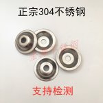
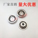
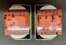
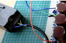
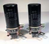
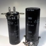
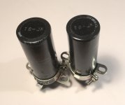
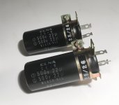
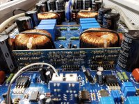
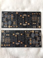
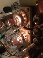
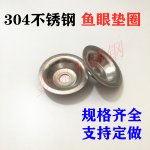
What is the name of this little component?

I noticed this on a Chinese page, but although I know how useful this component would be, I don't know its name. It would be easier to find more of them if I knew. And yes, I tried.

I think it would be very useful in constructing metal enclosures for electronics, such as amplifiers, CD players, etc.

Another interesting would be a tool that presses a similar shape into sheet metal.

Attachments

  • component_1.jpg
    component_1.jpg
    682.2 KB · Views: 581
  • component_2.jpg
    component_2.jpg
    621.6 KB · Views: 454
  • component_3.jpg
    component_3.jpg
    650.6 KB · Views: 448

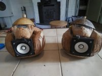
Mini Monitor DIY planar magnetic tweeters !

Since the release of some B&G knockoffs on a major website site i stop pursuing to make something that equals or comes close.. since there is no need. done and dusted. lets go back to why i even started a neodymium tweeter. and simplify the thing i wanted to make years ago.

The mini monitor loudspeaker/ planar tweeter

Part 1 introduction babbling away etc.....
Mini monitor revival - Part 1 introduction - YouTube
Part 2 making a single ended version
Mini monitor revival part 2 - Tweeter #1 - with first measurements - YouTube
Part 3 converting single ended to pushpull
Mini monitor revival part 3 - From Single ended to Push pull (with measurements) - YouTube
Part 4 a few tunes 🙂
Mini monitor revival part 4 - Music In stereo (Cheesy Disney edition) - YouTube

i made these kind of tweeters before, but thought i had to come along in the SPL war 🙂 but actually allot of woofers dont benefit at all from it. the woofers used are dayton DS135 86.6 according to there datasheet. but to make it able to sing (and even to hot on the top end) i ended up -9 db on the tweeters. and 2 dB BSC .... so there is allot of room to use simpler tweeters, and simpler tweeters usually means les crap in the way like magnets and steel etc. that makes the FR look like poo 🙂

Attenuate at the input?

ive built an lm1875 gainclone and after much tweaking i have to conclude that it just cannot sound 'right' below 20x gain as specified by the chip's datasheet. I imagine the thing will sound even better (read: more stable) at 30x gain or more, but the thing is i dont need all that gain and frankly will feel uneasy knowing that all the noise before the gainclone is being amplified unreasonably when i only ever need 1/3 of its output, not to mention the amp is now set to clip and blow the speaker if the volume pot is ever accidentally turned to max. And my preamp is opamp based so it already needs 3x gain to stay stable.

So does it make sense to put a fixed attenuator at the input of the amp if im not too concerned about messing up the input impedance of the lm1875 since i plan on buffering it anyways?

Headphones for recording

Hi all & hope all are well!! As I enter back into home recording, I'm in search of a set of headphones that I can use for extended periods of time. Having previously owned a 24trk home studio, I've been through the AKG's & the DF's, which now that I look back, weren't too weighted or uncomfortable, though things got a little hot,, but kinda accurate. So, with accuracy & comfort, in that order, what's out there to use with my 'in the mail' 24 trk digital workstation? My present living situation, though near perfect, leaves me a small window where I can do some loud 'pleasure' listening,,, So, what's the latest that won't require a 2nd mortgage.
Thanks in advance~

Fusion 15's vs Econowave Deltalite vs another option

I am officially ready to make a purchase on my dream, direct radiating, compression driver with large 12'' or 15'' inch driver with extremely high sensitivity.

The Fusion 15 at DIYsound group is without a baffle and crossover parts that's okay, but there service was dismal. Plus they don't have any Denovo DNA 360 to sell separately for future centre speaker. For $250 for woofer tweeter, ports and waveguide its average.

The Econowave deltalite 12 is a great option I can get the Eminence woofers slightly cheaper and the B&C DE250 should be around for a while to purchase seperately, overall it will cost me about the same.

The Econowave sensitivity is around 90db in the midband(dont even know what that means) while the Fusion 15 is 99db in general that's a big difference.

Does anyone know accurately the sensitivity for the Econowave deltalite 12?

Any other options around that $200 to $300 a piece for this type of speaker with higher sensitivity. These two options are the best minus the sensitivity issue with the Econowave.

The HTM 12 from sound group is also a good option including baffle and crossover parts but its out of stock.

Power amp Advise for a new repair technician

Hey guys,

So I've been the repair technician at a store for 3 months now and have managed to get to a stage where I can fix maybe 70% for the things that come through but when it comes to debugging Power amps that are either triggering circuit protection or have some distortion the only method I know is brute force testing every component and crossing my fingers. I'm also the only technician at this shop and have no prior practical experience/people I know to ask for advise.

An example of this is the denon PMA 350 I've been working on all morning. All inputs go through a selector switch, then an op amp, then some small transistors followed by the output transistors and relays. There's was distortion on the left side that made a 1k sine look like a square wave. I traced the sine wave through and out of the op amp into the transistor amplifier stage. On the emitter of the first transistor in this second stage The sin wave becomes a square wave. I tried swapping some transistors from the working side with the faulty side but the distortion is still there, making me think there might be some negative feedback in that section, meaning that all transistors in that area will show the distorted signal (I'm guessing?). Now the schematic online seams to have different board markings and a different components in general so I'm stuck there.

To my questions;
1) does anyone have a technique for testing transistors in circuit?
2) if distortion is generated somewhere in a section with negative feedback, how do you trace the signal to a faulty component?
3) if no schematic is available is the a more economic route to help make sense of the circuit than reverse engineering the whole thing?

Thanks for any and all help!

caps for altec bolero 690c crossover rebuild

caps for altec bolero 890c crossover rebuild

Altec Bolero 890c: Need 2 each 3uf caps and one each 6uf cap; can only find 3.3 uf caps and 6uf caps from seemingly dubious sources on ebay: Questions:1) are 3.3 caps too high uf rating; 2) can anyone recommend US sourcing;3)are there other acceptable, accessible cap values I can use instead of the ones above. This is my first recap and I want to get it right...Thank you all for assistance...Kindest regards, Warshard

Lundal LL 1670 grid choke

I think I have toasted a pair of these by applying too much heat when soldering leads to them🙁 I have 2 meters that act funny when I try to measure them and I get no sound from the amp when they are installed. Put the grid resistor back and works fine. I suspect I must have melted the internal connections to the pins. Could these be repaired or am I SOL?😱

DIY Help - 2

Making a new thread because where we started and where we are now is 2 completely different places lol.

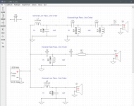
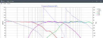
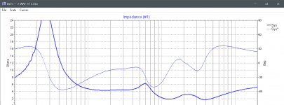
I'm currently looking at making a 3 way big bookshelf speaker that uses a DSA270-8 woofer, a RS52FN-8 mid and a RST28F-4. Crossed at 900 ish and 3400 ish in xsim. This is the best i could get in this program.

Hows it look, any suggestions? Am I a moron?? lol i really dont know much about this subject so any input is appreciated, thanks everyone.

Attachments

  • XSim 10_5_2020 6_02_25 PM.png
    XSim 10_5_2020 6_02_25 PM.png
    190.2 KB · Views: 212
  • XSim 10_5_2020 6_02_19 PM.png
    XSim 10_5_2020 6_02_19 PM.png
    158.8 KB · Views: 217
  • XSim 10_5_2020 6_02_31 PM.png
    XSim 10_5_2020 6_02_31 PM.png
    145.3 KB · Views: 204

Trying to find a forum for Driver Repair

There are some driver repair threads but they are scattered over a number of subforums. I've tried browsing those subforums and those postings are so rare, browsing isn't practical.

Being a total noob, dare I say this site, which looks like the 800# gorilla for DIY audio to me, should add such a subforum? - or are there other forums out there that are more attuned to driver repair (although I have not found any.)

Apologies,
Tom

Another newbie :D

Hey all,

I've been building DIY synthesizers and doing small woodworking projects for a number of years, so it was only a matter of time before I started looking at DIY audio!

Currently I have a decent listening setup in my home office (some Focal CMS65s with an RME interface and some acoustic treatment), but my living room is severely lacking! I've been scratching my head about the best way to build some towers that can be used for both music (likely streamed from a networked media server) as well as some home theater uses.

Could any of you help point me in the right direction about where to get my toes wet? It seems like home theater would require a multi channel receiver but audio would just need the audio source, EQ, and amp? Is there a good solution for tackling both?

Cheers in advance, looking forward to understanding all of this better!

Bass BIns, MBMs - Subs or Woofers?

Hey everyone,
If you were using a pair of MBM type enclosures as speaker stands, would you run them as subwoofers through the LFE channel on your reciever, or would you use a MiniDSP to cross over your main L&R channels to these MBMs and run the resulting channel full range on your processor?


Has anyone actively crossed over a normal speaker and a sub/bass bin/MBM to create a fullrange speaker? Or would I be better off simply replacing my front subs with these new guys and recalibrating my eq setting accordingly?

Meniscus Statements-How much power?

I am considering building the Meniscus Statement II speaker kit but am a bit concerned about how much power/current they need.
My best sounding amplifier is a Bakoon AMP 5521 but it is only 35 watts and probably not that high current.I suspect this speaker is sensitive enough but it might be too low impedance.I have not been able to find a minimum impedance measurement.
If the Statement II is going to need too much power any other suggestions?
I listen mainly to smaller scale acoustic music/jazz/blues/Indie folk.

Two of the same drivers - VERY different Fs...

Hi,

Very confused.

Just got a couple of 6" Tannoy dual concentric drivers.

They are the same kind of driver as was used in these:

Tannoy DC6i Compact Definition Install Loudspeaker

I'm trying to measure the Thiele/Small parameters of the drivers so I can design/build enclosures.

Measuring Fs on the drivers using this method:

Measuring Loudspeaker Driver Parameters

On one driver, I am getting an Fs of 104Hz, the other has an Fs 127Hz.

Using the exact same methodology for both, and switching back and forth the numbers are remains the same for each driver.

These are NOS drivers, and have never been used. Exact production dates are unknown. Tannoy has been of no help sadly.

Any thoughts on why there is this rather large discrepancy?

Thanks!

P

How to connect dbx active crossover

The dbx manual does not provide a diagram/drawing of how to connect a preamp/amplifier to dbx 234 crossover. I can't find a video in English that shows how to connect. Please help.

I'm attempting to connect 2-way speakers to an active crossover to a McIntosh MC2205 and a preamp.

Do I Connect the preamp outputs to the amplifier, the speaker outputs are connected to the crossover inputs, then the mid/high outputs and low/mid outputs are connected to their respective drivers on the speakers?

I've looked all over the internet and am confused...

Parallel 6N2 ECC83 12AX7 cold bias: how much is used??

Hello, I'm tesing a common chatode resistor of around 3-4 kohm with 500uA current (250uA bias per tube) and I like the sound in my parallel configuration.

Measured distortion is not so bad, but I'm using heavy GNFB and the resistor is bypassed by a cap.

I have 315V++ with 150Kohm common plate resistor. Plate voltage is 245V.

I don't see schematics with such low bias (even with just one tube and 6-8K cathode resistor), and I'm looking for similar solutions and possible issues.
Thanks

Hum problems with Boss CE-1 clone

Hello, I have the following problem.
I made a clone of a Boss CE-1 chorus pedal.
I have tried to make the problem visible through videos. Hence the links to Youtube.

51s42un.gif


rr2ase4ew.png


However, I have the following problem. When the pedal is activated, I get a lot of noise on my signal. This seems to 'dance' along with the chorus effect.
CE-1 Clone issues - YouTube

I did another measurement, and then you can clearly see that the supply voltages dance with the chorus / vibrato effect.
In this video it is measured on pin 8 of IC2. This is the + 14V. This is the AC voltage on the 14V. You can clearly see that the AC signal responds to the effect.
Meting CE-1 clone - YouTube

In the following video I have drawn out the time base and zoomed in further on the signal.
The yellow channel is -14V (pin 4) and the blue channel is + 14V (pin 8)
I assume that the power supply should be kept as clean as possible. Why could this be? All help and tips are of course welcome.
Meting CE-1 clone_2 - YouTube

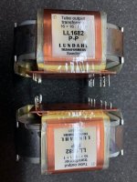
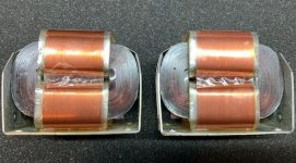
Lundahl LL 1682 PP Output Transformers Pair

For sell a pair of Lundahl LL1682 PP
5,5K Primary Push-Pull Transformers, good for several type of output tubes.

They have been slightly used, they are in very good (as new condition).

Price is 170€ for the pair + shipping (Please consult)

I accept Paypal.

Attachments

  • LL1682 1.jpg
    LL1682 1.jpg
    85.6 KB · Views: 352
  • LL1682 2.jpg
    LL1682 2.jpg
    90.9 KB · Views: 316
  • LL1682 3.jpg
    LL1682 3.jpg
    112.6 KB · Views: 310

WTB 2SA1265N/2SC3182N plus more

Hi, looking for right channel transistors for my Luxman LV-102. I received a non working Luxman and when I opened it it turned out to have been bathing in some liquid (most likely some oil) that had caused the right channel to short and frying some copper traces on the PCB.
I am in need of following

2SJ77 Toshiba
2SK214 Toshiba
2SC3182 Toshiba
2SA1265 Toshiba
2SC1904 FEC ?

Anyone?? Preferably I want the original Toshibas but I know that Hitachi have made some too if it is impossible with the originals.

Different Fs on drivers - what number to use for enclosure...

Hi.

Looking to build Voigt Pipes for a pair of drivers that I suspect will have different Fs values after break in. They are NOS and I have a thread going on them and the break in here:

https://www.diyaudio.com/forums/multi-way/361103-drivers-fs.html

My question is, with two drivers that have different Fs values, what number should I use for calculating the enclosure?

Thanks!

P

Reasonable Tube amplifier Hum / Noise

A neighborhood Audiophile brought me an ordinary vintage 6BQ5 / 12AX7 push pull amplifier, saying that he hears it has Hum, even with nothing connected to the inputs.

Having a quick look with my Fluke DMM, I measured 4mV RMS AC at the speaker terminals.

I measure 2V AC RMS on the 400V B+ - and single digit mV on the screen and 12AX7 B+. It uses a 5U4 for the rectifier and the power supply was designed to power a receiver, located in a different chassis. It has a large power transformer. No bottom metal panel; it's mounted onto a piece of wood.

I gave him some polyprop caps to replace the original coupling caps to the output tubes, as he told me he could solder. Inspecting, it appears he did this successfully. The 6BQ5 grids all measure about 4mV DC, except one, which is 30mV. (I believe this didnt change from what the original caps presented).

The AC cord is 3 wire, with the ground connected to the steel chassis. The grounding scheme of this amp is soldered directly to chassis, wherever was most convenient (i.e. no star or single point ground).

Are these values reasonable? What should a "good" reading be, in the circuit nodes I've mentioned? For a generic, vintage small tube amp operating correctly with no special power supply attributes, such as active regulation or choke filtering?

Thanks!

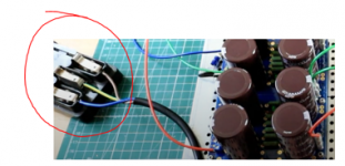
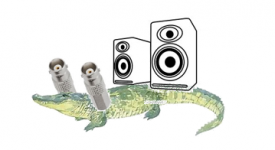
Please help me identify this crock device

Hi,

what is this device? What are its advantages? The youtuber calls it crocodile. It looks like a device that establishes an AC connection once shut.

The last attachment is to show that I understand that there are valid diy audio applications for actual crocodiles. I may come around to do this in a coming project.

Thank you.

Attachments

  • device1.PNG
    device1.PNG
    122.3 KB · Views: 200
  • device2.PNG
    device2.PNG
    154.3 KB · Views: 204
  • crocki.PNG
    crocki.PNG
    45.3 KB · Views: 201

Thoughts on 1/2 and 1/2 M2/AlephJ monoblocks

Been thinking about my conversion of M2 and AlephJ amps into mono blocks. The change results in each amp modded to contain one M2 board and one AlephJ board, with a heavy duty switch sending the power to one or the other.

All in all, it was a great change, both amps improved over their stereo single amp versions. Down points is the fact that obviously the two amps could not be used in two different systems, at the same time. A slight pain as I run several systems at home.

The other pain that occurred recently, was failure of one of the amps power supply. The amps being in mono block configuration, this failure took TWO amps out of service!

Thinking about this, I believe I will reconfigure the switch and amps like this:

Put both M2 boards back in the M2 and the same with the AlephJ...the switch will now determine if both channels or only one channel is powered up.

Like this I can use them as mono blocks like the 1/2 and 1/2 version, but flipping the switch would let them operate in stereo. Now they could be used in two different systems (switched to stereo), and failure of one wouldn't put both out of service.

Russellc

Directly-coupled buffer with only one supply rail?

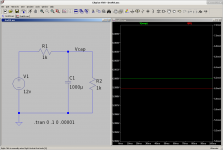
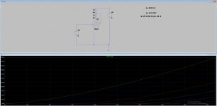
I've been poring over and simulating lots of class A buffer circuits lately, and I only just now realized you can hang a mosfet off of ground in the following fashion (see screenshot).

With a second copy of the circuit, you could build a buffer which has no input capacitor and no output capacitor, yet only uses a single supply rail.

Sorry if this is old news for many of you, but I feel giddy at this realization! I can build a directly-coupled buffer for my etymotics with just a wall wart 😀

Attachments

I post pictures of my current systems

I post pictures of my current systems here as background information. I will place a link to this in my profile.

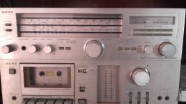
First, vintage Sony system. good power, good bass, but too boomy and the large speakers are on top of a large shelf because there is no place to put them. They are currently aimed at the topmost part of the opposite wall.

This is the system targeted for replacement by a DIY system.

Edit : The speakers are these as far as I can figure out (could not remove the grille)

http://www.thevintageknob.org/sony-SS-G333ES.html

Attachments

  • ssss.jpg
    ssss.jpg
    128.5 KB · Views: 524

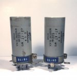
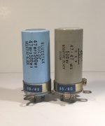
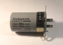
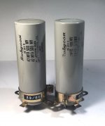
Rubycon,Nichicon,Elna Japanese High Voltage Capacitors for tube amplifiers.RARE.

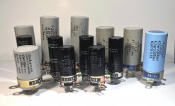
For sale rare and hard to find High Voltage 500V Japanese capacitors Rubycon,Nichicon,Elna for vintage tube amplifiers. Some used, some new NOS. All caps were tested and measured.


1.500V Rubycon 2x47uf /100mm x 35mm/$50 each - 2pcs. / USED

2.500V Rubycon 2x20uf /60mm x 35mm/$50 each - 1pcs. / USED

3.500V Nichicon 2x47uf /80mm x 35mm/$50 each - 3pcs. / USED

4.500V Bluestar 2x47uf /80mm x 35mm/$50 each - 1pcs. / USED

5.500V Nichicon 2x22uf /70mm x 25mm/$40 each - 2pcs. / USED

̶6̶.̶5̶0̶0̶V̶ ̶N̶i̶c̶h̶i̶c̶o̶n̶ ̶2̶x̶2̶2̶u̶F̶ ̶/̶7̶0̶m̶m̶ ̶x̶ ̶2̶5̶m̶m̶/̶$̶4̶0̶ ̶e̶a̶c̶h̶ ̶-̶ ̶2̶p̶c̶s̶.̶ ̶/̶ ̶N̶O̶S̶ / SOLD

7.500V Elna 2x22uf /60mm x 25mm/$40 each - 1pcs. / NOS

Attachments

  • IMG_1716.jpg
    IMG_1716.jpg
    391.3 KB · Views: 1,013
  • IMG_1687.jpg
    IMG_1687.jpg
    226.4 KB · Views: 1,003
  • IMG_1684.jpg
    IMG_1684.jpg
    221.4 KB · Views: 985
  • IMG_1718.JPG
    IMG_1718.JPG
    939.5 KB · Views: 972
  • IMG_1748.jpg
    IMG_1748.jpg
    174.1 KB · Views: 922
  • IMG_1755.jpg
    IMG_1755.jpg
    290 KB · Views: 142
  • IMG_1732.jpg
    IMG_1732.jpg
    359.9 KB · Views: 169
  • IMG_1735.jpg
    IMG_1735.jpg
    398.9 KB · Views: 240
  • IMG_1739.jpg
    IMG_1739.jpg
    212.1 KB · Views: 178
  • IMG_1731.jpg
    IMG_1731.jpg
    372.6 KB · Views: 191

FREE DH Labs Power Plus AC Cable

I have three 3ft pieces and one 2ft piece, of DH Labs Power Plus AC Cable. Typically about $10 a foot, but free to a good home! (Better than having it take up space in my closet...) Just pay shipping. I'm in the USA and believe I could get it all in a medium flat rate Priority Mail box, which would make shipping about $14 for all of it. That is probably worst case. People are also welcome to take less than all of it.


See my feedback on Audiogon on EBay, same user name.

3.5m male to male to connect two computers/phones

I am connecting a laptop(Thinkpad T480) to Thinkpad T430 or an Android phone so that one's audio output becomes another one's input and vice versa. Both jacks are TRRS CTIA (not apple). Mono would do. I assume I just need to buy something like this Audio cord, cut and resolder wires. Any idea what to what? I assume there are some more or less standard colors there.

Or else I would need to buy two trrs barrel connectors and wire them up. Right?

The purpose of this weirdness is to be able to call into voice conversations that happen on T480 using skype, teams, etc. So one would either call an android phone(auto pickup) connected to T480 or some VOIP phone number that T430 automatically responds to. Do you think this is workable? Or latency/quality will kill this?

Thanks,
Alex.

Questions about repairing a Nikko Alpha II power amp

Long story short, a friend of mine gave me a Nikko Alpha II power amplifier that had a scratchy right channel. I figured it would be a great project to learn how to fix up an amplifier. Keep in mind that I have no formal education regarding electronics, and my knowledge of circuits is very, uh, rudimentary.
Here's what I've done to it so far:

  • Replaced all capacitors on the power supply board and amplifier boards. Several of them on the amp boards were leaking, a couple had leaked quite a bit. I should note that the protection circuit board, the only other board in the amplifier, had already been serviced when I got it.
  • Replaced all of the wiring on the main transistors (the ones attached to the heatsink) with jumpers, since the circuit boards they were mounted to were degrading and losing their connection (hence the scratchy left channel)
  • Replaced the 4 power capacitors with caps of the same voltage rating and size, to make mounting the new ones into the chassis as easy as possible. The originals were 10,000 uF/63V, the new ones are 22,000 uF/63V.
  • Replaced one capacitor on the protection circuit using jumpers, since it seems to be degrading in the same way as the transistor PCBs with the traces coming loose. (I should note that the amplifier and power supply boards are made of a different, higher quality material and are holding up just fine)
Every fix I've done has usually resulted in me gacking something else up, so the state of the amp has been between one channel muted to the other channel muted to functional--at one point it worked but when I put the chassis and heatsinks back together, a bare wire shorted a one channel and a cap on the protection circuit's PCB trace came loose while I was checking it. The most recent repairs were the power cap replacements and fixing the capacitor on the protection circuit board.


Now, I've turned it on, and hooked it up to my speakers, and it produces music... that sounds like garbled ****. In particular, the midrange and lows mostly sound fine but the treble in both channels is severely clipped and warbled. I've tried this with two different sources, speakers, speaker wires... to the same result.


Interestingly, when I turn the amplifier off... it keeps playing music for maybe 10 seconds, WHICH SOUNDS MOSTLY FINE. The clipping (99%) is gone.


Any idea what I should be looking for? Are the new power caps too much, or did I mis-wire something... maybe something with the transistors again? (Also, if anyone has a website that could ELI5 transistor bias in an amplifier that would be deeply appreciated, most of what google produces goes way over my head). Would it be possible to replace the protection circuit board with something generic that isn't degrading?

Thanks in advance to any and all help!
Faulty Pyramid PA310

I have this pyramid pa310, very good amp. I had replace the 50k potmeters, becuz they were faulty, after playing for some time, the amp goes into protect mode ( the relay clicks out), I have to wait atleast 10hours then I could play it back, but after 10 minutes of playing it clicks out back


I took it to a technician, when I got it back, and turn it on the relay clicks right away without any delay..... and I think he tuned it becuz I'm getting 83watts per channel which it suppose to be ~~~35watts per channel.....


But there is still a problem with the amp when I connect both channel the right channel starts to play very low and distorted but If I Turn it off and and plug out the left side Input, It start to play normal. Same problem applies to the Left side too


I think the technician had changed two Output transistors from the left


Any idea what may be the problem

And any idea of how I could make It have the delay protection when I turn it on 😀


Thanks....

loudspeaker measurement amplifier

Hi there,
I have measured and built a good number of speakers over the past 15 years doing measurements using old amps that I had or found at thrift shops. I am thinking of building a small portable amp to measure and design speakers. I have a couple of questions:

I know that Class AB is typically the recommended type of amp. I believe that Class D (or T) is not recommended due to a floating ground but I may be mistaken and love an explanation regarding this.

Also, if anyone has built a very basic amp just for this purpose, I would love the opportunity to copy your work. I have looked at LM3886 builds and although I think I will try one some day, for now, it seems like overkill for my immediate purpose.

Thanks,
Jay

First project :: XU216/AK4499/OPA1612 :: DAC Pinout & circuit examples

Hi 🙂

I've a bit of experience with Altium Designer, C/PP, general MCU stuff, things like I2C and so on. I'd like to have a crack at making a decent DAC to level up my elec skills. I'm hoping this community could be of help.

I'm at the first hurdle, finding accurate footprints/models to avoid naming 128pins or more. I'm going with the AK4499 to start. Also noteworthy, I'm doing a prototype using TQFP or similar SMD packages to keep things simpler. My first query is, where's all the chip info? I've read the datasheet which is pretty light, very little examples of circuit diagrams/schematics which is a bit surprising but it's at least not the es9038pro hiding behind an NDA. (Great dac though, no hate here) I'm also curious about what the numerous identically named pins are doing like that, no doubt there's method there that I'm missing but either way it's always nice to have clearly labled gpio/input/output/control(i2c etc)/power.

I'm starting to work up the I/V converter section according to the data sheet and I find things a little confusing (on the aforementioned points).

If anyone has thoughts, ideas, examples, anything to kick start a discussion on the topic that'd be great. Even if it doesn't address the points I've made, still all learning is good learning.


Cheers
TIA

Dayton 8" FR PS220 Discussion

This thread is about the Dayton 8" Neo FR driver.

PS220

Which as of this post is now in stock it seems.

The main thing is that this is NOT a DECWARE driver, but a discussion of possible mods and applications seems appropriate.

There is a separate thread on the DECEWARE driver. Here:
DECWARE THREAD

Fwiw, I ordered two just to see for myself... and for fun.

_-_-bear

Tubes in an opamp feedback loop?

Disclaimer 1: I'm posting this in the tubes forum because I doubt it would receive much attention in the headphones forum (seems mostly ss over there). Sorry if it was a mistake.

Disclaimer 2: it involves opamps, don't :whip: me.

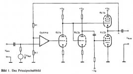
This said, I once had a nice headphones amplifier which made use of the following topology:

353077d1370560011-tubes-opamp-feedback-loop-prinzip-jpg


It was a kit by Helmut Becker from Audiovalve (see details here: PCL805-Roehren-Kopfhoererverstaerker_von_Helmut_Becker).

Of course, I could just clone it, I've got all the information needed. But it was in fact more powerful than needed (especially for the hd650 I've got now) and I was wondering if a simpler version couldn't be made, using ecl84 rather than ecl85.

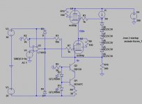
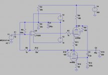
Here are two ideas (see attached pics). They are determined by what I've got on hand (a good 300Vdc supply, a quad of ecl84) and the schematics are just concepts (lacking dc protection and the like).

The first one uses three supply (-20/+20/+300), is dc-coupled (which is stupid... output caps might be safer) and uses a cascoded cathode follower inside the opamp feedback loop. About 25ma standing current.

The second one uses a White cathode follower output inside an opamp feedback loop. Which means input and output caps and a floating PS for the opamp. Same standing current but can deliver a lot more current into the load.

Any of these looking like a worthwhile summer project ?

Attachments

  • Prinzip.jpg
    Prinzip.jpg
    19.8 KB · Views: 1,254
  • lunatic1.JPG
    lunatic1.JPG
    52.2 KB · Views: 884
  • lunatic2.JPG
    lunatic2.JPG
    57.6 KB · Views: 873

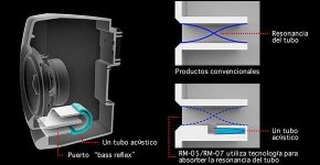
reflex silencer and cabinet

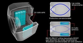
looking on the net I came across this particular the two attached images

both the reflex tube and the box use helmholtz resonators to break down the standing waves and improve the sound.

The question is: seeing that the measurements of the box and the reflex duct are known, is it possible to create an Excel sheet to calculate the resonator?
It seems like a very simple but at the same time effective idea.

maybe you can also do a retrofit to existing speakers

Attachments

  • box silencer.jpg
    box silencer.jpg
    28.1 KB · Views: 139
  • reflex silencer.jpg
    reflex silencer.jpg
    23.9 KB · Views: 146

Marantz CD-65DX transformer temperature?

Hi, should I be concerned if my "new" Marantz CD-65DX gets pretty hot? Even if not playing a disk with just screen lighted. I measured 68℃ (155℉) at the surface of the transformer. The ambient temperature is 27℃. And plugged in a watt meter it shows 20-23 watts. Is this temperature normal for this player?😕 It works fine and sings beautiful without any other problems... Thanks.

Transistor matcher and curve tracer

Latest project is as per title.
it is basically just an inverting stage where base vs collector voltages are measured and sent to pc via usb and displayed.
the curves can then be compared for a match.
the base voltage is a simple pwm into an integrator.
i use diff amps to convert between micro 3.3v and collector 9 volt supply and then back to 3.3v for a2d converter.

On baffle step and SPL

Hello,
I am playing with simulation of real speaker system including baffle size and room effects. Many questions arose...
I clearly loose 6 dB in deep bass so I must make mids and twetter less sensitive to make SPL flat.

But:
1. in real living room reflections from the floor (mainly) and also from rear wall return back some decibels
2. if I see real measurements of commercial available loud speaker I dont know other parameters of measurement except 1W/1m. It is measured with big additional baffle? They removed any reflections? What are standard measurement conditions?
3. if baffle step is there (no additional baffle added) it is hardly believed that someone can achieve 96dB sensitivity and 20Hz +-3dB (HiFi sound)
4. every little change of speakers position in the room, or placing in different room completely change the sound. It makes sense to buy 20t Eurs loudspeakers for standard living room?
5. as in previous item it makes sense to playing with drivers position and crossover parameters when I dont have exact knowledge about room parameters?
6. It makes sense to go into shop's listening room to choose loudspeakers? That room is for sure different from in house room.

What has been your favorite "small" folded midbass horn (at least to 100Hz) and why ?

What has been your favorite "small" folded midbass horn (at least to 100Hz) and why ?

and by "small" lets say no larger maximum than a Peavey FH1 (~10 cubic foot bulk) with hopefully less than that cabinet's 24 inch depth. Better yet - vs La Scala's 8 cubic foot bulk.

Size, path, St, Sm, driver size, etc. - subjective impressions,thoughts, on tradeoff, associated mid/treble horns.

LM3886 hum

Hello,
I've build audio amp with 2x LM3886. Power supply is unregulated +-30V. The signal goes to the preamp first.
The problem is that I can hear quite audible 100 Hz noise. When I'm changing the volume the hum is the same so when playing loud I cannot hear it, but if want to play quietly I can hear the hum. I tried to disconnect LM3886 signal input wire (not signal ground, just signal +) and the hum disappears.

The blue waveform is power supply ripple voltage, pp voltage is 150mV.
The yellow waveform is the humming output of amplifier. It looks like there are small 100Hz squares which last during the rise time of power supply ripple voltage.
View attachment IMAG001.BMP

I amplified the humming output using inverting op amp and it looks like this:
View attachment IMAG003.BMP

Do you know where the hum is coming from and how to eliminate it? Could it be from ripple voltage of power supply or bad grounding? Thanks

CT Sounds At7000.1d

The output section isn't kicking on for some reason. I replaced all of the 21844s chips, all of the transistors and all 3 op-amps on the board. All rail voltages are present and all of the regulators are working. Also I have a working version of this amp I can reference from im just out of ideas.

Attachments

  • 20200913_030425.jpg
    20200913_030425.jpg
    1 MB · Views: 153
  • 20200913_030436.jpg
    20200913_030436.jpg
    1.1 MB · Views: 175

FOR SALE : Yamamoto sockets and stuff

Hello all,
I have the following Yamamoto stuff. All brand new

One UX-4 socket. Gold pins. $ 35.00
Four Octal sockets. Gold pins. $ 40.00/each

two mounting plates for Octal or UX4 sockets with all necessary screws and silicon dampers. Really neat way to attack vibration issues. Check out JAC's site. Part # 320-074-76 and 320-128-89. $ 20.00/each

Ten teflon/gold 5Pin Solderstrip. 1L5P-TEF. JAC p/n 320-046-51. $ 6.00 each.

Shipping will be quoted depending where you live. USPS priority mail. You pay the postage I'll cover the insurance.
Would prefer US only. International buyers please understand I will not ship the cheap way ( First class mail international ) as it can not be insured. I will ship internationally, but the postage and insurance is on you. Sorry.
PayPal only.

thanks for looking and be safe.

Cheers, Crazy Bill

Threshold FET nine

Last year I experienced some “hiss, crack, pop” noises from the pre.. every two minutes or so.

I did not use the pre since last year.


I hooket it up a few days ago, played some music (knowing the noises would be in the background) ..

Well.. today, I only listened to it the last couple of hours, with no music playing (if the music is playing I would not be able to hear it!, its that low)... I wanted to hear these noises again ... but they are completely GONE right now! :scratch2:


Will it maybe come again you think?

I may have changed my setup a bit since last year/last time playing with the FET nine.

I am not sure but maybe I also got a new fridge since last year, don`t remember exactly when - could this be the cause.. or what could make the noises go completely away?


I made a thread last year about the problem.. and never found a solution. (But thought I did for a while).


Regards René

replacing cs4814

hi guys
im using a audio-note cheapy dac,it originally had a cs4812 reciever chip which i replaced for a cs4814 one which was pin for pin compatible, it seemed to clean up the sound quite abit while still keeping the musical flow and sound of the audio note dac.
however ive noticed this is avalible
DIR9001 to CS8412 or CS8414 Pro Version Converter Board on eBay (end time 09-Dec-10 15:47:53 GMT)
and was wondering if this would be another step up,anyone have any views on this item,approach,it states lower jitter which obviously is a good thing but i dont want it to kill the audio notes musical approach...would appricate anyones views,ideas on this.
all the best
smithie

Line array across a car/truck window?

I’ve seen some home theaters with line arrays from floor to ceiling. How hard would it be to incorporate this across the front window with say 1”-2” drivers? Or even across the back window of a truck?
As far as the R-L stereo channels are concerned let’s just pass on that for now (I’ll cross that bridge later). I was just wondering if this could be done in a car / truck format.
I though this would be a fun next project but first I wanted to see what you all think.... bad idea?

Any links to help get me started or driver recommendations?

helpneeded High Voltage PSU Rebuild- Northeast Science Company RE-6506P

Hello Everyone! I am in the process of fixing a High Voltage Regulated Power Supply that I purchased off eBay for 200 Flat (Sold as Broken) - probably made in the early 1960s. The unit is made by the Northeast Scientific Company in Acton, Mass. Model Number RE-6506P I have serial Number 22 interestingly, I checked to see if the company was still around but sadly they are out of business as of 2017!

I was not able to find any documentation for this unit from the usual sources. More than anything I am seeking a schematic. I do not want to have to make one but if I do, I promise I will publish it for free. Tube Complement is as follows

5x - Glow Discharge 5651A
1x - Beam Power 6FW5
3x - 12AX7 Twin Triodes
2x - EIMAC 4-125A

When I acquired the device, only one tube would light up when it was switched on Standby, I got the rest on after fixing some cold solder joints and bypassing a bad winding in the filament supply with a different transformer. I have turned on the B+ section and I am very close to have this device in working order, (I Hope)

The voltage rises to 500 Volts on the output but the current meter is near the maximum of this supply (300 watts at 50ma well at 6kv) and the plates on the 4-125 begin to turn red. When I select 1000 Volts - it gets worse and the ma meter becomes pegged - the supply is in overdrive state. In addition you will note that 1 of the 5 glow discharge tube is not glowing? I have no idea if it comes on at a later point or if it part of the problem.. The tube that is out connects to one of the capacitors I had to replace.

I don't know where but somehow the voltage is being discharged or leaking probably via a faulty component. What I need most is a schematic - does anyone have any experience with power supplies produced by Northeast Scientific Company?

See pictures attached for more information ...

Any and All Information including Suggestions are Appreciated: Thank You
Keith

Attachments

  • redtubes.jpg
    redtubes.jpg
    446.6 KB · Views: 132
  • tubeglow.jpg
    tubeglow.jpg
    798.9 KB · Views: 137
  • boardview.jpg
    boardview.jpg
    712.4 KB · Views: 131
  • NEPSU.jpg
    NEPSU.jpg
    425.9 KB · Views: 121

Quicksilver 8417 Clone - Revisited with ESL-988

Wow, its been about six years since completing these mono amps with advice from many here. Always thought it sounded good, but just didn't wow me as much as the Pinkmouse Krell Clone and other SS amps I had...

Original Post:

Quicksilver 8417 Design - Stay with it or modify?

Anyway, I now have Quad ESL-988 and hearing that they love tubes, I decided to try the Quickies out...very clean and pretty much best I have heard.

Staying true to the QS 8417 circuit, but with SS rectifier, 47k /.47uf coupling caps, individual dual bias pots, and KT120 output tubes, it sounds great.

One thing I did differently this time is I pushed the bias on the KT120 as far as I could, all the way up to 100ma @400V on KT120 plates (the power tranny is good for 220 ma), and I measured around 210 ma out of power transformer (with the added current of 12AX7 and 12BH7 PS). I eventually backed it down to 88ma each tube. I always ran these tube at around 50ma not wanting to push anything...maybe running too cold was the reason it was just meh?

Anyway some questions -

(1) I have Edcor Output transformers that are 60 watts. No matter what I drive thru the KT120, I am only getting at best 60 watt output. Upping bias just puts more of those watts into Class A, correct?

(2) Since staying true to 8417 design, only half of the 12AX7 and 12BH7 are in use - is is beneficial to parallel the tubes? Add the diode to the output tube grid?

(3) Edcor Power transformer rated at 220ma - is it a problem running near that limit? The power transformer gets warm but not hot like my old ST-70 power tranny (like real hot). There is plenty of room on the KT120 at 400v as far as bias, and I am only at 35 watts on a 60w tube. Should last quite a bit longer, right?

I also now have a Doge LP8 as a preamp and may be one of the reasons I like this setup so much. I very impressed with the Doge.

Any advice appreciated!!

Thanks

LR4 Phase shift and driver polarity

when we use LR4 xover then there will be exact 180 degree phase shift happens right on the center of the midrange frequency. Is there anything to consider in flipping the midrange polarity? When LR 4 is 360 degree phase shift crossover and quiet surprised why this 180 deg phase shift happening?

Attachments

  • image_2020-10-07_003000.png
    image_2020-10-07_003000.png
    22.9 KB · Views: 172

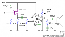
Help with Ruby Amp

I am trying to build the popular Ruby LM386 amplifier circuit on a breadboard, but cannot get it to work correctly.

The output is extremely low and distorted. And the gain control potentiometer does not appear to change anything.

The JFET input stage is also significantly attenuating the signal, as the sound is noticeably louder if I connect the guitar input straight to the LM386, bypassing the JFET. (But still pretty low compared to a pre-made LM386 module)

I have used all the same value components as in the schematic, expect for the JFET which is a 2N5484.

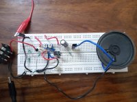
Would appreciate any inputs on how to troubleshoot the circuit. A picture of my breadboard layout is attached.

Attachments

  • 0-2.jpeg
    0-2.jpeg
    73.6 KB · Views: 171
  • unnamed.png
    unnamed.png
    2.8 KB · Views: 152

Phone application as a simple function generator?

(Hope it's the good place to post.)

Hi,
Was looking for a simple and cheap function generator. First checked on ebay then realized that there are applications running on phones that can deliver up to 20-22kHz signals through the headphone plug.
As anyone tried or is anyone using this kind of application as a simple function generator? If yes, any app to recommand, qualitywise?
Thanks.

TU8600 front panel decals

Is there an easy way to remove the pre-printed Volume, Headphone and Power black labels on the front panel of the TU-8600? With just three things on the panel, I don’t need the reminder, and all the rest of my equipment is silver with either no labels or very light white labels.

Before I try to soak, scrap or heat the printing off, does anyone have a suggestion?

Thanks, Dave

Question: matched inductors for BTL output?

Hi everyone, I can't find an answer to this question and would like to hear from anyone who can explain the theory and show measurements.

"Matched" components in various amplifier topologies are an advantage in gain-matching as well as distortion cancellation. Is there any advantage in closely matching the L/C/R characteristics of the filter components in a Class D BTL output stage? Most of the components specified for Class D amplifier filters have a large tolerance eg +/-20%. Would it make any difference to have +/- 1%?

Thanks,
Mike

Naim NAIT crackle at power-on - cause?

I have a v1 NAIT that has suddenly developed a soft crackle in the output at power on. This occurs immediately (before the mute circuit goes off), is independent of an unaffected by the volume control, and comes from both channels. The crackle disappears eventually, usually in a few seconds, sometimes in minutes, sometimes almost immediately.

This is a daily use amp and was apparently professionally serviced/recapped 2-3 years back by a former owner. I can't find a schematic for the v1 NAIT online anywhere and although it's clear from the symptoms that something must be affecting the power amp section in both channels (thus maybe in the power supply?), beyond doing capacitor swaps I'm not super duper experienced and I'm not really sure where to probe, esp without a schematic. Does anyone have leads or suggestions? Do these symptoms ring any bells?

Thanks!

Limits of Audibility

:cop: Thread split from - Ak4499 noise at iv opamp output :cop:
...still way below audible limits regardless.

There are no specific hard limits of audibility. Existing published limits of audibility are estimates of the average limit of audibility for a population. That mean 50% of people are estimated to be able to hear below the limit, and 50% of people are estimated to not be able to hear below the limit.

What is the best way to plot ultra linear curves in LTspice?

Title basically says it all. Im trying to plot UL curves for various tubes, and my methods aren't quite working. No matter what I do, the current seems to be much lower compared to what people have measured on a curve tracer.

For reference, here is what I am comparing my simulation to The EL34 Tube

Attachments

  • DIYaudio ULcurves.jpg
    DIYaudio ULcurves.jpg
    941 KB · Views: 100
Projects by fanatics, for fanatics
Get answers and advice for everyone wanting to learn the art of audio.
Join the Community
507,909
Members
7,893,325
Messages

Filter

Forum Statistics

Threads
406,473
Messages
7,893,325
Members
507,909
Latest member
BenM74