Ultra low-cost receiver (Tuner+Amp) project

Motivation
Traditional FM radio has its benefits- one of which is an unlimited supply of free music. With the advent of local radio stations that play a variery of music from the past and do't talk too much, listening to radio has become interesting again, at least for short periods of time.

A line-in will be needed as well, for an MP3 player or CD player or both.

Bluetooth is also a possibility.

Feasibility Testing
The feasibility of this project is already tested, using a transistor radio costing less than $10. The sound quality is fully acceptable, and considering that the radio uses an LM386 chip, albeit it bridged mono mode, sound quality is not expected to be an issue.


1) Satellite subwoofer home theatre system through headphone output

Sound quality - suprisingly good, though lacking bass. Distortion most probablt due to broken antenna.

2) Un-enclosed Radio Shack 6" 40-1011 woofer driver with sensitivity of 93 dB/W/m

Acceptable sound quality

3)Sony SS-G333ES speaker

Sony SS-G333ES on thevintageknob.org

These are large speakers, consisting of a 8" woofer, mid-range, and a high quality tweeter.

Sound quality was acceptable, something I could live with. Sound pressure levels at 1 metre was measured at 75dB/W/m at half volume with distortion attributable mainly to the FM reception. Connecting a long wire to the FM terminal cleared things up considerably.

All this from a transistor radio powered by 3 volts of batteries.

FM Section
The FM IC used on this little radio is a CD9088CB. Output is to one speaker although the headphone output seems to be stereo,

Tonegen Tweeter Replacement? Axis LS28/LS88

I know these sorts of questions come up all the time and there is no easy answer...

I have a set of Australian Axis speakers - LS88 and LS28 and a matching centre. The high frequencies on the LS28 and LS88 have all but disappeared - which I attribute to the aging Tonegen tweeter (94L65DS-03HD; 442TND).

I believe these tweeters were used in many speakers through the ages.

There is even a thread on re-doping them (or a very similar model):
How to Re-Dope Snell Tonegen/Foster Tweeters (Model E, J, K; gens. I & II) | Audiokarma Home Audio Stereo Discussion Forums

In addition to the re-doping, there is also ferro fluid that may or may not need to be replaced depending on if or if it isn't in there. In any case, I'm not sure if I'm up to taking these apart.

Anyway, have been looking for a replacement - unfortunately they have an in between cut out diameter (~94mm) and the LS88 has an extra magnet glued to the back..

Any ideas?

Mmini regulator (sample offering)

Hi
My friend designed two regulator with very small size. He is willing to offer PCB sample to member on diyaudio forum.

Dual regulator : SIZE: 82mm X 59mm
Positive regulator : SIZE: 65mm X 41mm
Supply voltage range : 5V -- 80V

here are the pics of the regulators:
dual
15VUMRDual.jpg

positive
PRO2Power.jpg


This is the PCB:
dual
NEWUMRDUAL.jpg

positive
pumr00f1.jpg


Schematic:
dual
UMRsch01.jpg

positive
PUMRsch01.jpg


The mounting on chassis:
UMRHT.jpg


each member from DIYAUDIO can ask for one sample PCB(dual or positive). Because the different voltage has different BOM, please tell me output voltage you need. Only 20pcs of samples for each reg.

Applyer only pays the registered airmail shipping fee 3.00USD.
My email address: coffin@diyzone.net

cheers

Coffin:smash:

Good software/app for making drawings of rooms and cabinets?

I'm going to be helping someone put audio in a newly purchased home, and also want to do some projects in my own. Also, once I get past some personal stuff, I want to FINALLY make* some custom speakers and matching cabinets.

I've made some crude albeit scaled room sketches in PowerPoint, but that's not going to serve easily for 3D cabinets. And for rooms, I feel there must be something simpler. Once upon a time I used Google Sketch-Up, or are there better choices by now?


*Not myself, my detailed woodworking days are past. Any LA-area recommendations for cabinet makers (speakers and stereo cabinet, not kitchen ha ha) very welcomed.

Antique radio bluetooth mod - stereo/mono conversion

Hello all

I have got an antique radio with a nice casing, and volume knob that I am thinking of repurposing.
I would like it to have a line-in, and a bluetooth function. Unfortunately the radio can only accommodate one speaker, and I think i will look for a 5.25 inch driver.

I want to power it with a suitable board. I found many, with the appropriate power, line in, and bluetooth, and volume control (which i intend to interface with the original knob).


Here is a good example of a board I'm considering


But these are all stereo. I am a little at a loss as to how best to convert to drive a single speaker. I see advice about combining the line-level signal using simple resistor Y-shaped configs, but not clear about how to combine a class D L/R output to mono.

Any tips would be greatly appreciated.

directly coupled class A buffer for low-voltage headphones (work-in-progress)

After lurking for a bit a looking at lots of designs, I've started cobbling together my own.

This is a class A buffer for low-voltage headphones, with no input or output capacitors (similar to the directly coupled B1 buffers in this forum).

This is intended to drive my Etymotics, which only need about 0.2V.

There are three "channels": right, left, and a virtual ground return.

The source follower is an IRF510, and the constant-current sink is my tweak on something jerluwoo posted in https://www.diyaudio.com/forums/sol...ource-ccs-audio-applications-post4785961.html

It seems to simulate fairly well 🙂

Haven't actually built it yet, that's next 😀

This is my first "real" attempt at making an amp, so any and all feedback is welcome!

Attachments

  • hpa-nocap-IRF510-TIP122-r2.asc
    hpa-nocap-IRF510-TIP122-r2.asc
    22.6 KB · Views: 107
  • Screenshot_2020-10-06_03-33-41.png
    Screenshot_2020-10-06_03-33-41.png
    31.3 KB · Views: 697
  • Screenshot_2020-10-06_03-33-18.png
    Screenshot_2020-10-06_03-33-18.png
    84 KB · Views: 702
  • Screenshot_2020-10-06_02-42-09.png
    Screenshot_2020-10-06_02-42-09.png
    71.9 KB · Views: 670
  • Screenshot_2020-10-06_02-41-44.png
    Screenshot_2020-10-06_02-41-44.png
    71.7 KB · Views: 666

Eminence Delta Pro 18 A in prism sealed 150 liters

Hello

This thread is the continuation of a cartoon that started here:


Vintage JBL for subwofer

I transcribe the text of my notes:

DEFINITIVE DECISION :
CORNERS !
I will use this two furniture, the white will be for the box and the red for the front panel.

Box:
Prism
Volume 300 liters gross
Design: sealed
QTC: 0.550
Perfect transients, although less SPL, this is compensated with a gain of + 3 db in each box when increasing to this volume ..
So for the same SPL will need half the power (watts)

These pieces of furniture have been a gift from a friend who did not use them anymore.

They serve ? he asked me .....

The next day they were in the hall, WAF asked where we would take the dog for a walk, for the same place that we will enter and leave, I answered, or is not he another member of the family?

The prism (irregular) will be 0.50x0.50x0.70, and the height of the box of 1.40 meters.

Soon I will attach the results of the simulations with WinIsd

Ohhh, I will have to make many gifts (and many invitations to go out to dinner) to my wife, these monsters are not easy to accept in a living room ....
I am a lucky man, yes sir ! 😉

Attachments

  • IMG_20181028_184053.jpg
    IMG_20181028_184053.jpg
    820.2 KB · Views: 1,801
  • IMG_20181028_181504.jpg
    IMG_20181028_181504.jpg
    870.7 KB · Views: 1,752

Transformer based 6db preamp

My latest diy preamp adventure. -/+ 24v Linear Supply. Sparkoslabs regulators. LSK489 for the jfet’s. 6 layer PCB (s/g/p/p/g/s). Startup / shutdown muting.

Balanced -> LL1676(1:2) -> jfet follower -> 10k ladder -> jfet follower -> dc blocking cap -> RCA

I will post measurements soon.. the in/out are flipped on the case.

Attachments

  • D36E5E56-57CC-4523-AEB4-917D24256B2F.jpg
    D36E5E56-57CC-4523-AEB4-917D24256B2F.jpg
    1 MB · Views: 740
  • 2113D6D5-EB64-4403-A71D-1E9C6FE63446.jpg
    2113D6D5-EB64-4403-A71D-1E9C6FE63446.jpg
    979 KB · Views: 709
  • 1EE2312B-77E5-417B-8327-309723928F88.jpg
    1EE2312B-77E5-417B-8327-309723928F88.jpg
    964.1 KB · Views: 687

GF1002 (PAM8403) not working but overheating?

Hello everyone,

I am building a project with a DF player and a GF1002 (based on PAM8403). The problem I have right now is that by pressing the play button on the DF player, there is no sound, however the GF1002's IC is heating up. I have attached my current wiring diagram.

This scheme worked before I hooked everything on a PCB, which probably have destroyed my previous GF1002 (+ and - were shorted) - it also heated up.

However now I have brand new both DF player and the GF 1002. When I connect only 1 speaker to DF player (to pins SPK1 and SPK2), it works.

What have I done wrong?

Attachments

  • wiring.jpg
    wiring.jpg
    244.6 KB · Views: 1,102

Full Digital Amplifiers with PSVC (Power Supply Volume Control)

Hi,
According to TAS5558 datasheet:
The TAS5558 supports volume control both by conventional digital gain/attenuation and by a combination of digital and analog gain/attenuation. Varying the H-bridge power-supply voltage performs the analog volume control function.The benefits of using power-supply volume control (PSVC) are reduced idle channel noise, improved signal resolution at low volumes, increased dynamic range,and reduced radio frequency emissions at reduced power levels.

The TAS5558 also features power-supply-volume-control (PSVC), which improves dynamic range at lower power level and can be used as part of a Class G Power Supply when used with closed-loop PWM input power stages.

I wonder is there any examples of Full Class D amps which implemented this (or similar) concept on volume control stage? I think this concept overcomes one of the big concerns in audio when used with full digital amps.

Attachments

New enclosures for PC speakers -

This project is about creating better enclosures for the 3.5 inch speaker drivers that came with my PC speaker system that was converted to an amplifer in this thread:

http://www.diyaudio.com/forums/chip-amps/283845-pc-speaker-electronics-amplifier-conversion.html

Removing the 3-inch speaker drivers and testing them externally yielded some interesting and encouraging results. Placing them in cardboard boxes generated a surprising level of clarity and some semblance of bass.

The speakers do sound better when 'liberated' from their enclosures. There are several reasons for this, as far as I am able to ascertain. The speaker grille probably cause a lot of diffraction, and also resonances. The box formed by the front of the speaker enclosure and the speaker box also causes some level of 'boxiness' and resonance.

I hope to design and build speaker enclosures for the speakers.
Specifications:

Impedance: 4 Ohms
Power Handing : 3 Watts
Size : 3 inches

Measurements:

Frequency response : 100Hz to 12,000 Hz (pure tone)
Max output : 75 dB at 1 metre

long actuator tumbler switch

I am looking for a SPST tumbler (toggle) switch which has a long actuator/handle (at least 30 mm long).
When browsing the internet, I stumbled across a switch from APEM in its 600H series.
In that series APEM has also types with actuator lengths 30mm and 40mm. But looking for a supplier I cannot find that type.
Can somebody on this Forum help me with this problem.
It is in fact not important which manufacturer but as long as it can supply that 30mm actuator it is O.K.
In the attachments I show which type I mean.

Attachments

  • Apem-Tumbler-Switch-2.png
    Apem-Tumbler-Switch-2.png
    85.1 KB · Views: 135
  • Apem-Tumbler-Switch.png
    Apem-Tumbler-Switch.png
    80.8 KB · Views: 129

Airplay data dropouts bug or not?

Hello,
I am investigating one problem with airplay streaming involved in signal chain. Longer story is here
Short story is that it began from shairport-sync issues. But i got same problems without shairport-sync involved.And that is just mind blowing. I played 20khz sine signal from mac to airport extreme latest version and firmware and got the same crackling sound due to dropouts about 384 samples lenght. I am out of ideas, so want to be more sure that not only me getting this. Anyone having apple at both ends could test this. Just generate 20khz sine over airplay to other apple end and see if you experiencing this. Why 20khz? Because this is the most easy way to find a problem if it exist. Make sine just below 0dbFs and play. Please play for 2minutes at least. The problem could take time to appear.
Anyone experiencing the same please let me know.

Thanks

Attachments

  • dropouts_about_342samples_lenght_-20db.JPG
    dropouts_about_342samples_lenght_-20db.JPG
    201.4 KB · Views: 69
  • jack_alsa_glitches.JPG
    jack_alsa_glitches.JPG
    147.7 KB · Views: 69

Removing Scratched in Speaker Veneer

I have Mission 770 with pretty sever scratches on the top ... any tips for getting them out - short of re-veneering, which I'll not do

Pictures show after light sanding with 600 grit to remove high spots, light soft pencil scribbled to identify "layer", light sanding with 320 grit to remove pencils marks - damp wipe to remove sanding dust. Still looks like hell.

Attachments

  • IMG_9910.jpg
    IMG_9910.jpg
    831.9 KB · Views: 203
  • IMG_9911.jpg
    IMG_9911.jpg
    994.8 KB · Views: 199

Dealing with internal standing waves and port leakage

While doing some experiments on my speaker, I placed a piece of plywood in the back of the enclosure behind the woofer at a 45 angle pointing upwards:

attachment.php


That didn't really change the output of the woofer, which was my original goal, but I discovered that it significantly reduced (smeared) a 850Hz peak I had in the port output.
When I flipped this reflector to point to the bottom of the enclosure, that effect was gone and the peak came back.
I also tried putting a piece of high density rockwool in the middle of the enclosure behind the woofer, and the effect was kinda midway between the reflector and no reflector.
(see attached measurements)

As far as I understand, the reflector changes the path of the wave from the back of the woofer, shifting the resonances to different frequencies, and overall, scatters it around the enclosure.
I'd love to hear your thoughts and explanations, maybe there's a better/easier/more proper way to achieve this?
Also, if you know any good articles on how to deal with the sound inside the enclosure, please share. There is plenty information about stuffing but I didn't find much about the cabinet shape, construction, effects of slanted walls etc.

Attachments

  • p1.jpg
    p1.jpg
    116.8 KB · Views: 345
  • p2.jpg
    p2.jpg
    112.7 KB · Views: 1,040
  • d1.jpg
    d1.jpg
    289.5 KB · Views: 350
  • d2.jpg
    d2.jpg
    290.1 KB · Views: 341
  • d3.jpg
    d3.jpg
    279.7 KB · Views: 205

Replaced Audax HD100's with Audax tw025a0

Dear people from Diyaudio,

I have struggled quite a bit before trying to solve my issue with the help form this forum. I play with a pair of wonderful mission 717's with a bit of an upgraded cross-over. After modifying my amplifier I heard an issue in my speakers. Both have a slightly different version Audax Hd100 tweeter. To solve the problem I bought the tweeter known as the "Direct replacement for...". After measuring I deal with a +/- 6dB difference. The man who sold me the tweeter kindly helped me and we measured an L-pad for the tweeter. Sadly enough just an L-pad doesn't solve my problem.

To sketch the situation at this point, the original crossover is as following:
Low pass: 1,6mH coil in series.
High pass: 6,8uF capacitor in series, 0,20mH paralel.

Simple, yet effective.
The current situation follows this + a 2,7 ohm resistor series, 5,6 ohm resistor paralel. With this impedance making it a 5,8db attenuation.

I can't honestly say that I feel like I need this or that, it's just not 'there' yet, and I'd love to get some suggestions. I made my filter external so I am able to 'play around with it'.

Hope someone can put my tweeter on the right track, I can feel it's 'almost there'....

Inductance of low pass filter & bass driver on group delay ??

Hi,


I am lost in the uderstanding of group delay and also on how to choose the inductance characteritics of a bass driver.


I believe to know a coil for a low pass is adding a lot more of inductance that the driver has itself at those low frequencies. How much is it important in the choice of the bass driver please ?


What about a 8" having a Le of 0.2 uH like modern drivers with low efficienty and trade offs with older design with maybe 0.5 to 1 uH ?


My understanding is the lowest inductance gives the best group delay or am I mixing the concepts, i.e. missunderstanding the thing ?


I especially asking myself what Le range should be preferabily chosen when we need to pick up a mid bass drivers, these 6" to 8" drivers that are asked to make 50 hz as 800 hz ??? Is there a threshold where we should don't care anymore cause too much difficult to manage below a limit ? For instance 100 hz or else at seing for instance some waerfall in the bass areas ?!


How much should I care of the inductance in the datasheet, then in the coil filter for a first order low pass, please ?


Sorry if I am mixing up the thing too much btw...


Many thanks if you could beginn to enlight me...or give me simple path to follow fon howw to consider the Le of a bass driver.

4P1L Alternative

I've been using 4P1L as PP driver in my GM70 PP amplifier and like the sound. I used it in place of 46 as they are hard to get. The 4P1L is transformer coupled to the GM70.

As usual the 4P1L is very microphonic and that is beginning to concern me. I'm not entirely sure if it makes a difference but if the music is loud and cut off suddenly (lifting the cartridge off the record) a ringing can be heard that fades out; like a small bell.

I'm looking for suggestions for an alternative that is relatively easy to get, not too expensive. Preferably directly heated but I might have to concede on that.

ADCOM GFA-585 Power Amplifier Rear Heatsink Assembly Pair Only

Used ADCOM GFA-585 power amplifier rear heatsink assembly pair in excellent condition. They do not include any semiconductor devices nor emitter resistors, and possibly other parts may be missing. Sells and ships to USA residents only. $125.00 plus shipping; PayPal with transaction fee.

Attachments

  • IMG_2416.jpg
    IMG_2416.jpg
    551 KB · Views: 141
  • IMG_2417.jpg
    IMG_2417.jpg
    592.2 KB · Views: 129

FS Troels Gravesen Faital 3WC-15 high sensitivity floor standers

These speakers are the original ones as built by Troels - I was lucky enough to buy them off him directly as he was short on space and another one of his projects had to be moved on. Speakers will come with full build / crossover details.

UK buyer preferred, free delivery in England/Wales - dispatch outside of this possible but it might be costly.

Asking £3000 based on parts cost - good deal considering the kit price and sheer amount of baltic birch plywood used and huge amount of time Troels put into these.

They put most commercial speakers to shame - for example Spendor D7.2 at over £4K is nowhere near the performance of these (I have directly compared). I personally believe something like the Spendor classic range or ATC SCM100 SE would be a more comparable speaker.

These ones are fitted with the beryllium tweeter.

These have similar DNA as ‘The Loudspeaker’ but in a smaller package.

Original webpage for the build:Faital-3WC-15

Condition is mint.

Attachments

  • 48DDBC78-8009-47EF-8E08-4AE38140B1AA.jpeg
    48DDBC78-8009-47EF-8E08-4AE38140B1AA.jpeg
    399.3 KB · Views: 777
  • 0F4B4062-250E-4E09-887D-9914D9573836.jpeg
    0F4B4062-250E-4E09-887D-9914D9573836.jpeg
    260.8 KB · Views: 770
  • 91BAA40F-1AD3-450A-99BC-7D3254714616.png
    91BAA40F-1AD3-450A-99BC-7D3254714616.png
    260.5 KB · Views: 742
  • EDBDF7AE-2CE9-4473-8A3B-53F9308946EF.jpeg
    EDBDF7AE-2CE9-4473-8A3B-53F9308946EF.jpeg
    380.9 KB · Views: 759

An unusual electrostatic AMT DIY approach - an attempt, at least ...

As a happy Quad 63 listener, Dipole-DIY-er and fascinated by the AMT Mid-Tweeters ... why not face the challenge to mix that all together into yet another, this time slighty more experimental DIY project for me: A non-standard AMT with an electrostatic drive ...
ES_AMT_1.jpg

I started with the Idea of a folded AMT-curtain which would have some 4:1 depth-to-width ratio and would result in some sort of max. 4:1 compression ratio, if the membrane would perfectly move in parallel (which is not the case). I designed not much deeper, because of possible lambda/4-resonances.

The membrane is hold into it's curtain shape by carbon rods which are manteled by shrinking tube. These rods can rotate in the plexyglass holders so to allow some repartition of the membrane tension.
ES_AMT_4.jpg

On both sides of the array there is a V2A steel rod, letting stretch the membrane and slightly play with the tension. After the tension seems ok, the membrane has been further stretched with a hot air gun. The electrostatic load of the membrane is fed by one of these V2A rods.
ES_AMT_2.jpg

Each fold of the electrostatically charged membrane has on both sides 5 straight copper wires driving the audio signal to it. Because everything should be symmetric, in theory there would not be any lateral forces on these copper wires. Wirewise, a wire either pushes, or pulls both adjacent menbrane folds. All these 5-Wires-Arrays are alternatively fed by the high tension audio signal. One set is fed from the top, the other set with opposite polarity from the bottom. The distance from these arrays to the membrane is some 2mm, as everything is set up on a raster of 2.54mm.
ES_AMT_3.jpg

The transformers are 220V-5V types, which gives a theoretical ratio of 1:44 when inversely used. To archieve enough high Audio signal Voltage, two of them are used, totalling to a ratio of 1:88. In order to get some 4kV audio signal, the nominal 5V inputs of the transformers must be fed with some tenfold 45V...50V. Therefore, to avoid saturation of the iron core, this setup must not be fed with signals below the tenfold of the nominal 50Hz, e.g. not below 500Hz.
Transformers.jpg

The static high voltage is provided by a Cockcroft-Walton multiplyer, fed by a commercial inverter for cold cathode lighting, the latter outputting 700V ... 1100V / 5mA at a frequency of 30kHz. The diodes are 2kV/3A types, the capacitors are Wima MKS 2kV/100nF types. So at the end of the miltiplyer chaint there must approx. be some 4kV.
CockcroftWalton.jpg

So, hooking all together ... and driving it with an old faithful Yamaha AX 590.

Three different membranes have been measured. Twice (red/green) membranes cut out from an aluminium damped emergency blanket. KISS for the beginning, because it is a standarded and readily available (I know, I know, way too much conductivity ...). This kind of membrane material is very noisy by itself, very self-resonant, which leads to really messed-up acoustic results between 500Hz ... 5kHz, full of resonances. And also a huge and broad peaking above 10kHz. Because of these resonances, something completely different was used for a third attempt: Give it a chance with a self-adhesive aluminium ribbon, all along with it's protective PE-strip-off-layer (blue). This provides a nice self-damping sandwich membrane, a much smoother sweep audition, but an akward loss of SPL around 10kHz. So in the end, none of these two membranes were suitable. And I am reluctant to dive into self.made soap/graphite/magicmixtures coating of unobtainable membrane brands. Unless someone knows THE solution ...
Amplitude.png

Besides the resonances there was way too low SPL: 80dB, and when driving it louder, then the sparks went firing ... for the case of the safety blanket, each spark was evaporating some of the aluminium coating (sort of a nice self-limiting process, indeed). The foil itself was robust: The sparking was not punching a hole into the foil.
Membrane.jpg

So all in all the project is/was a fail until now. But it was fun, and I learned a lot about electrostatic LS. And I luckily am still alive, despite handling HT.

I have not given up completely, though: Maybe someone has some most welcomed constructive critics / remarks / hints?

Attachments

  • ES_AMT_1.jpg
    ES_AMT_1.jpg
    156.6 KB · Views: 728
  • ES_AMT_2.jpg
    ES_AMT_2.jpg
    93.7 KB · Views: 617
  • ES_AMT_3.jpg
    ES_AMT_3.jpg
    126.4 KB · Views: 588
  • ES_AMT_4.jpg
    ES_AMT_4.jpg
    108.2 KB · Views: 607
  • Transformers.jpg
    Transformers.jpg
    141.8 KB · Views: 573
  • CockcroftWalton.jpg
    CockcroftWalton.jpg
    161.6 KB · Views: 346
  • Amplitude.png
    Amplitude.png
    40.9 KB · Views: 382
  • Membrane.jpg
    Membrane.jpg
    70.6 KB · Views: 377

B&K 1640 Linear Regulated Power Supply

B&K 1640 mobile equipment power supply in good condition with manual. Discrete linear regulated design provides 3 amp continuous current and voltage adjustable from approx 10 to 15 volts DC. Vintage 1980s. Has auto-reset overcurrent switch.

Sells and ships to USA residents only. We have closed our audio shop due to retirement. $40 plus shipping; PayPal with transaction fee added.

Attachments

  • 1640.jpg
    1640.jpg
    117.2 KB · Views: 141
  • 1640_2.jpg
    1640_2.jpg
    110.4 KB · Views: 139
  • 1640_3.jpg
    1640_3.jpg
    145.6 KB · Views: 140

Analog Devices AD743KN & AD745JN Opamps

I have NOS genuine Analog Devices AD743KN (9) and AD745JN (11) for sale. The 743s will work well in ROTEL RQ-970BX phono preamp upgrade and the 745s are excellent for ADCOM GFP-565 preamplifier phono stage upgrade (along with required resistor and capacitor changes). These were sourced from an authorized USA distributor and have been long out of production. We have closed our audio service/upgrade shop due to retirement. $20 each plus shipping. PayPal with transaction fee added. Sells and ships to USA residents only.

Attachments

  • AD743.jpg
    AD743.jpg
    128.2 KB · Views: 88
  • AD745.jpg
    AD745.jpg
    105.7 KB · Views: 86

Hello My name is Brad.

Hello everyone. My name is Brad. I have been lurking around this site for many years(about 20). Back in my teenage years, I was really into home and car audio during the early to late 1990's. Now that I am a married homeowner, I have an interest in building a few projects for my house and as well as my cars. A lot has changed since the late 1990's, and I would like to catch up on the current technology. Back in the 1990's I was a huge Cerwin Vega fan, and I am currently a fan today. Going back 25 to 30 years ago, I remember amplifier power was quite expensive being between $2-$5 per watt. Today, I see that there are amps out there with a lot of power for significantly less money. I also see many new companies out there. I am glad to start posting, as I have so many questions since I was active building stereo systems over 20 years ago. Thank you Brad

Sub miniature tube headphone amp site.

Hello, does anyone here know what happened to the site of an Korean or Taiwanese Sub miniature tube headphone amp site ?

I visited the site last in 2013 but i cant find it anywhere anymore.
This guy made beautiful tube amps in, to me, impossibly small mint tins.

All battery operated.

I downloaded one project of his the "amp head micro" but even googling on that name or reverse picture lookup doesn't give any results.

If any one knows where to find more documentation that would be great.

Kind regards Oliver


His name is sijosae. Old site is "http://www.headphoneamp.co.kr/ftp/sijosae/Gallery/"

Attachments

  • Amp_head_micro.png
    Amp_head_micro.png
    56.8 KB · Views: 455
  • FinishedTop.jpg
    FinishedTop.jpg
    808 KB · Views: 584

Troubleshooting low frequency humming in PC speaker set

My Logitech Z-2300 unit suffers from an audible low frequency humming. My observations about the humming are as follows:

  • The humming comes from both satellite speakers and the woofer speaker. Though I'd say the humming from the satellite speakers is slightly louder.
  • The humming is independent from the volume setting on the control remote
  • The humming is present with and without an audio source connected to the 3.5mm input
  • When disconnecting the satellite speakers and the woofer speaker, the humming is no longer audible. Though I can hear a similar humming (same pitch) originating from the toroidal power transformer, but it is much less audible.
  • The humming remains audible when only the woofer is connected (with satellite speakers not connected) and when only the satellites are connected (with woofer speaker not connected).
  • The humming was also present in my previous home.
Upon researching this issue on google, the most probable culprit would seem to be a ground loop. Note that the unit does not have a ground terminal (it uses a two terminal plug). I've disconnected all other appliances in the room and connected the speaker set directly to the wall socket, but the humming still persisted. Nevertheless I have been unable to exclude a ground loop as the cause of the humming. Can a ground loop be a problem considering the device is not grounded to the mains? Perhaps the issue lies with the grounding inside the unit? Would this manifest itself as a humming tone?

Upon googling further, I found a common problem in the Z-2300 is a subpar mechanical joint of two ground wires. See Logitech Z-2300 subwoofer hum solved! | YourITronics. I replaced the mechanical joint with a soldered joint, but unfortunately this did not mitigate the humming.

I then spend some time measuring the power supply circuit of the Z-2300 with my DMM but I couldn't find anything suspicious: mains voltage appeared over the primary coil, the secondary was at 40.2V AC and I measured 54.2V DC after the bridge rectifier. Measuring the rails for the MOSFETs, my DMM reported an initially high ripple on the DC voltage but after a while the reading would stabilize to less than 1V (note this was with no outputs connected).

I then proceeded to try and de-solder the output caps on the bridge rectifier (in order to measure their capacitance, I don't own a ESR meter) but have been unable to desolder them due to all the epoxy on the PCB. As the two big caps still look in good condition in the pictures linked below, I'm doubting whether they are causing the humming.

The similarly between the humming from the transformer and from the speakers leads me to believe the transformer might be the culprit? While reading on transformer humming, I typically read about mechanical humming. In this case the humming from the transformer sounds more electrical though. Is there anything I can try to determine whether the transformer is the culprit? Unfortunately I don't have access to a bench power supply, I only have a DMM (though it can read capacitance and conductance).

Finally, can anyone suggest any further steps for troubleshooting the issue?

Link to imgur album.


edit: replaced images with link to imgur.

Infinity RSA 250 repair.

Looks like this is a "rare" amplifier? Not much information out there on it. I have been running it as my 3rd spare LOL.


Started doing a weird thing where there would sometimes be no audio, but if I turned the volume way up it would start to play for a while, then stop. Figured I'd open it up and see what's going on.


One of the MOSFET's (looks like the power supply section) let out the magic smoke. 2 more have bad solder joints. Seems simple enough, but I am not sure what is the correct part.


Silk screen on the board says T3055, Part itself is BUZ71A. T3055 is kind of generic, lots of parts come up. BUZ71A has some more specific results, but seems to be obsolete. Found one site that had STP16NF06 as an x-ref.


I understand it is risky buying parts on Ebay, but what about Amazon?? Or, best to stick with the reliable part houses (Mouser, Newark, etc.)


Looking for someone smarter than me with experience to suggest the best route for replacement part?


Thanks!

FS: legendary Paravicini The Head TX-4 MC SUT

Hello,

Sadly, but I am selling my Paravicini The Head TX-4 MC step-up transformer. It is in very nice condition, with very small signs of usage, but considering it's age I would consider it perfect. I've been using it for many years with great pleasure and I hope it will get into good hands.

It's a legendary SUT with magnificent sound. According to my best knowledge only 200 units were made, this is No.28. They show up for sale very rarely so now it is your opportunity to get one.

Item is located in Budapest (Hungary) and I am happy to ship it globally. I will pack it very carefully.

Asking price: EUR 2.290 plus shipping

If you are interested, please send me a PM.

Attachments

  • IMG_2199.JPG.330cf6f8643c54c75d5674496afe6636.JPG
    IMG_2199.JPG.330cf6f8643c54c75d5674496afe6636.JPG
    173.5 KB · Views: 343
  • IMG_2200.JPG.0c993e4c2ea27a3cfe90b56d92ac6e94.JPG
    IMG_2200.JPG.0c993e4c2ea27a3cfe90b56d92ac6e94.JPG
    192.6 KB · Views: 401
  • IMG_2201.JPG.39279a88baa2d3d5d28d48c5e5f4c0b6.JPG
    IMG_2201.JPG.39279a88baa2d3d5d28d48c5e5f4c0b6.JPG
    193 KB · Views: 317
  • IMG_2202.JPG.a2f164f7b2e853a384ead03a775857fe.JPG
    IMG_2202.JPG.a2f164f7b2e853a384ead03a775857fe.JPG
    157.2 KB · Views: 309
  • IMG_2203.JPG.680e8f320f554ebb673f7a7a425bf6f4.JPG
    IMG_2203.JPG.680e8f320f554ebb673f7a7a425bf6f4.JPG
    217.2 KB · Views: 283

FS: Lyra Clavis D.C. with silver coils

For sale is my Lyra Clavis D.C. cartridge rebuilt by ANA Mighty Sound in 2018. Since then it has been played only a few hours and it has been sitting in my drawer.
ANA Mighty Sound just recently checked it and they found everything perfect. Cartridge looks and plays as new.

Rebuild includes:
- silver coils
- Ogura PA stylus on boron cantilever
- new silicone damper

VTF: 18 mN
Coil impedance: 6,1 ohm
Tracking: 100 micron / 315Hz

As you can see it tracks better than when it was brand new.

Don't underrate this cartridge, with the rebuild its quality has been raised significantly, with the silver coils inow t plays in a much higher league.
Amazing 100 micron tracking ensures not to miss a note from the record.

Asking price: €790 including express international shipping.
I am also open to serious offers.

Photo shows actual item. You can buy with confidence, I am long time member on DIYAudio.

Tx8BeGq.jpg

nW6U9Kg.jpg

YhGLvtm.jpg

QRvOD4Z.jpg

e2dzVOQ.jpg

9WZKC4Ph.jpg

Nv4Aqueh.jpg

tEzL31u.jpg

FS: Audio Tekne MC-6310 low impedance MC cartridge (silver coils)

For sale is my Audio Tekne MC-6310 low impedance MC pickup. It has been rebuilt by Ana Mighty Sound and it sounds very lovely.

Rebuild includes:
- new coils made from silver wire
- new cantilever with Line Contact stylus
- new damper (silicone based)
- cleaning, alignment, testing, fine tuning

VTF: 20 mN
Tracking ability: 80 micron / 315Hz
Coil impedance: 3,4 ohm

Stereophile recommended components under phono cartridge category class A.
New price was around 4200 euros.

Asking price: €1450 including FedEx International Priority shipping.
I am also open to serious offers.

I have the photos of the rebuild and I am happy to share some with potential buyers.

3kAnENz.jpg

ktsWIRj.jpg

DniFGKG.jpg

sSNqwhn.jpg

s8skzw5.jpg

KF87qRn.jpg

YzuiREL.jpg

d0uztKU.jpg

lFPgnrS.jpg

Phase issues

Hello,

I've got a pair of small fullarange satellites in a 2.1 system with some serious phase sifting in the low-mid treble region. The sats consist of the PS95 driver in a 2.8 liter box with a 14cm baffle without any passive filters, and a 8's sub for everything lower than 100hz. Take a look at the REW measurement ( dont mid the high bass output this is just how i like to hear my computer speakers with some extra bass) i am curious about the multiple phase shifts in the 1k-5k region. I dont notice something significant by ear, but maybe that's because i havent listened to a lot of speakers. The mesurment is taken form my ear high right in the middle of the speakers (which are about 1 meter apart and have a slight tilt inwards. Is this significant? what might be causing this?

Attachments

  • das.png
    das.png
    316.6 KB · Views: 138

Tricolumn speaker with f88 Fountek

An externally hosted image should be here but it was not working when we last tested it.


Here is an idea of a tricolumn speaker using the f88 (or other small speaker). I've designing it using the specs from the paper "Now,a tricolumn- build this efficiente column spekear" by R. N.Baldock. Two questions:

1. How to model it with Hornresp? Simply use parabolic sections? There are some discontinuities in the interfaces between the 3 cylinders (one of them is not a cylinder)...

2. Or just go for it with a thumbnail calculation based on the resonance frequency (L=c/(4*f)) and taper ratio of 1/3, height of the inner tube d=2*L/3 (part 2 of the paper)?

Thanks.

Cyrus iii amplifier problem

Hello!
I recently acquired a Cyrus iii amplifier for cheap and was wondering if it's worth more than parts. I would really like to fix it but I'm not quite sure where's the problem. When I turn it on with the power switch in the back, amplifier displays different combination of leds (see attached pictures) almost every time and the front panel buttons or volume control aren't responsive. Power indicator shows green or both green and red at the same time. I guess that there is a communication problem between the chips in the front board (the one with the buttons). Can anyone confirm my suspicion? I've soldered and desoldered surface mount components before (no destroyed pcbs so far), so I'm willing to give it a try to repair the board.

Attachments

  • 20201025_205425.jpg
    20201025_205425.jpg
    661.1 KB · Views: 212
  • 20201025_205353.jpg
    20201025_205353.jpg
    450.7 KB · Views: 217
  • 20201025_205433.jpg
    20201025_205433.jpg
    569.8 KB · Views: 229
  • 20201025_205403.jpg
    20201025_205403.jpg
    583.9 KB · Views: 244
  • 20201025_205418.jpg
    20201025_205418.jpg
    550 KB · Views: 450
  • 20201025_205343.jpg
    20201025_205343.jpg
    526.8 KB · Views: 160

Denon PRA 1500

Hi dear DIY colleagues!

I bought me a great vintage denon poa 2400 power amp and pra-1500 preamp.
Sounds nice but when i change the preamp by a newer denon that I still have (pma1055). Well, then i prefer the sound of the latter.
When listening to the pra1500 I experience listening fatigue and it’s like I’m really missing dynamics and the highs are really overly bright...

I didnt’t notice anything physically wrong with capacitors. So I bought me a cheap capacitor tester and started disassembling some capacitors (randomly). I measured the two biggest capacitors (right after the transformer), then some in the tonal circuit. But they all measure fine.

I could measure all, but first I would appreciate some feedback from you people.

Do older capacitors affect dynamics and tones?

Even if they measure fine, should i replace them? Consider their age: + 30 yrs old.

Could i be measuring wrong?

Maybe its just the sound of the preamp? Find this hard to believe though, cause the preamp Im using now is really low end. But sounds better.

One more thing: the transformer does have a hum. But still outputs a nice 23,6 volt.

Thanks for your thoughts on this one!

Ps: i attached the manual (part of) of the pra 1500

Gr

Willem

Attachments

Jamo 23274 sub? or bass driver

Hello: I just acquired these drivers; any body have any info about them?
I was told they were used in a factory passive sub about mid 1990's vintage.
The person I got them from gave me no specs except for a piece of paper stating
cabinet volume of 4 cu ft. & a crude diagram of the port & it's internal distance
from the cabinet. No info as to where to put port front or back.
I'm going to try to attach some pictures.

...................... thanks

.................. Fred petersen

Attachments

  • Jamo1.JPG
    Jamo1.JPG
    152.8 KB · Views: 167
  • Jamo2.JPG
    Jamo2.JPG
    177.4 KB · Views: 163
  • Jamo3.JPG
    Jamo3.JPG
    136.8 KB · Views: 155

fS: "Blown" Schiit Vali I headphone amp

It could not swing the voltage into a set of lousy Koss 250 ohm cans to play percussion at a good level. Trying to do the same with a Zhaolu DAC's headphone amp literally smoked the Zhaolu's amp section.

It distorts like hell and assume transistors - not the sub-minature tubes, are cooked.

Don't know the shipping - have to find a box - would guess under $10 first class in the US

$25 sans shipping.

If restored to proper working condition, I would not recommend use with high Z cans.

Schiit would not provide a schematic so one is on their own.

The power supply will not fit a "small" Priority box. The DAC and PS
of course would fit the "medium" Priority box but that's around $15.80.


fFzSXFy.jpg

z9rEFUc.jpg

WFW FAST / WAW with SBA racetrack woofers and SB65

The idea came from xrk971’s 10F/RS225 FAST thread.

I was looking at woofers I could get around here since the Daytons are not available locally, and shipping here is prohibitive.

A distributor with good pricing recently showed up for SBAcoustics, and it got me excited that I may find a suitable woofer, as I already had the Visaton B80 laying around.

Going through the SBA website is no joke! There are so many products, it’s easy to get confused.
I was going nuts trying to find a match to the RS225, then I stumbled onto their new 5x8” race track woofer.

It looked ok to try and I shared the idea on the 10F thread.

That’s when BYRTT pointed out that c-to-c using the 5x8 woofers and a small full range driver would be very interesting, and how about a MTM, or in this case WFW?

The data that BYRTT shared pushed me in that direction easily. Having played with XSim and the manufacturer’s curves, I thought it had great potential.

So, I contacted the distributor, and 2 days later, all 6 drivers showed at my door, COD for only $6 shipping cost! That’s service!

BTW, as a plug, this is the distributor in Taiwan, should anyone be interested. They are very nice, and they speak, or write, Chinese as well as English.

thlaudio web site pages

So, this will be a thread on how it will turn out in the end.
I have an idea, but I may change a few things along the way according to measurements, I’m not inflexible.

Shall we start?

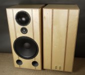
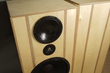
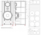
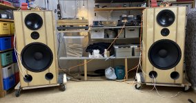
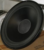
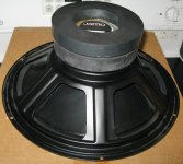
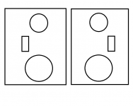
So, as we already know, the woofers will be the 5”X 8” SB15SFCR39-8. Two of them per enclosures.
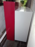
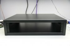
The enclosures will be sealed.

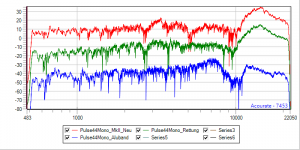
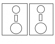
Inside, sandwiched between the 5x8s will be a 2½" SB65WBAC25-4. It will have a sealed space inside the enclosures. This driver has been reviewed as having a great dispersion and great high end reach… close to a tweeter.

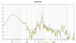
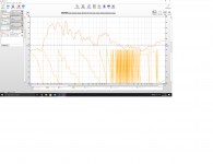
These are BYRTT’s measurements of this driver, in FR and dispersion… pretty good!

729115d1547527213-10f-8424-rs225-8-fast-ref-monitor-1011-png


729116d1547527213-10f-8424-rs225-8-fast-ref-monitor-1012-png


MTM, or in they case WFW, improves the vertical polars, as more data shared by BYRTT showed here

720061d1544007135-10f-8424-rs225-8-fast-ref-monitor-polar_perceval-png


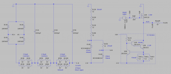
After I build them an enclosure, I’ll first try a simple 1st order XO, but will probably settled on a more elaborate one later on…

720090d1544017406-10f-8424-rs225-8-fast-ref-monitor-xsim-wtw2-jpg


720265d1544090690-10f-8424-rs225-8-fast-ref-monitor-screen-shot-2018-12-06-6-00-34-pm-png


I’m sure I forgot something, but this is the beginning, so, I’ll keep adding up.

Experimenting with imaging in a 3-way design

Hey all,

I will be honest. I have been working with audio for many years, engineering source parameters as an ME, and I am taking a deep dive into building my ideal mastering main speakers.

No need to go into tons of detail in terms of driver specs etc too much. The plan is to use a 10" sub, 6" mid, and planar tweeter.

Many of my favorite designs use an MTM -type format, at least with the tweeter below the mid. Grimm LS1 and Stratus Gold come to mind.

Another thing I've noticed in the best presentations I've heard is having mirrored tweeters on the outside of the speaker. This seems to improve imaging as well, although in a different way than MTM.

I have a terribly inaccurate two-second mockup that shows two concepts for the design. Would love to hear people's opinions about what would perform better.

If anyone is interested in more aspects of the design, I'd be happy to share them. I just figure that I'm verbose enough as it is. haha

Attachments

  • mirrored pairs.png
    mirrored pairs.png
    16.8 KB · Views: 164
  • non-mirrored pairs.png
    non-mirrored pairs.png
    6.1 KB · Views: 159

38 - 40 volt Reg P/Suppy

I'm looking for a simple 38 - 40v 150ma P/S built around an LM7824.

I thought a 15v Zener on the centre pin with an 8k2 from the o/p pin, to make sure the reg. is not starved, should jack it up to 39 volts as I have all the parts lying around.

But, the LM7824 is rated for a max i/p of 40v. - Am I correct in assuming this refers to the max i/p voltage between i/p & centre pin, & as long as it is below 40v here, it should be OK.

The total input voltage I'm feeding to it is about 46 volts which should leave about 31 volts between the i/p & centre pin.

Comments please.

Will a modern budget DAC beat a high end 1990's DAC?

Hey fellas,

Having recently been made redundant it may be time to downgrade some of my Hifi gear 🙁 First to go will be my DAC. It's a Trichord Pulsar DAC that I bought used a few years ago, although it cost £1400 back in 1994.

My thinking is to replace with a modern budget equivalent (CA DacMagic), which sells for around half the price of the Trichord on the used market (£150 vs £300) - I'll pocket the difference into savings.

Reading up the on the DacMagic's specs it looks as if DACs have come a long way the 15 or so year between them so I was hoping the audible difference will not be that great. Before selling it, curiosity has got the better of me and I've decided to see what is in the Trichord component wise to compare:

An externally hosted image should be here but it was not working when we last tested it.


An externally hosted image should be here but it was not working when we last tested it.


To my surprise there are two toroidal transformers housed inside the main DAC, as well as an external PSU!

An externally hosted image should be here but it was not working when we last tested it.


Compared to the DacMagic, there are obviously far more quality component with regards to capacitors and power supplies, although the circuitry seems far simpler.To be expected, given their respective age gap of 16 years:

ImageShack® - Online Photo and Video Hosting

What do you guys reckon? The DacMagic has had plenty of praise since it's release I am hoping the far more advanced chipset/DAC chips will compensate for it's relatively cheaper output stage and wall-wart power supply...

Since there is a 15 year difference between the designs, this seems feasible to me, or am I dreaming?! Since the £150 saving I will get by "downgrading" is fairly modest, I don't want to do something I regret.

Thanks for any advice

Fusion Tempest 12 crossover

Purchased a bare bones Fusion 12 kit from DIYSG back in August 2020. Erich was able to provide me with a list of crossover parts but no photo or schematic of the crossover. My last email response from him was in August when he stated that he would provide some sort of assembly instructions for the crossovers. Have emailed several times since then but no response.


Wonder if anyone would be willing to share this information, privately of course. Would like to run this by Erich but I would not be asking for this if I were able to get in contact with him.


Not trying to be a pain, and I know Erich has been busy moving. My guess is he has not been able to come up with this info and is too busy to research it at present.


Any help would be appreciated
Charles Sedivy
csedivy22@gmail .com

Crossovers for coaxials... no lobing?

Hello. I've recently received some Seas T18 coaxial drivers. I've quickly thrown them into some sealed enclosures I had which provide a qtc of between .5-.6 according to calculations. I am using them close the wall and one is near a corner in a fairly near-field apartment listening setup. With some very rough measurements and based on what I can find online I've dialed in some basic crossover options into my mindsp SHD and measured to ensure they sum to a fairly similar FR. This driver seems to allow for 1st order crossovers, Seas uses 2nd order for their Loki kit, and I noticed their minidsp active preset they provide for the Loki uses 4th order LR with some EQing to flatten FR further. So far they sound pretty good! It's my first time using coaxials and I'm enjoying the 'solidity' to the sound when moving my head. As I don't always sit in the same place on the sofa and often move around the room, I can def notice a more cohesive less phasey sound when not in the sweet spot which I'm enjoying.

What I'm trying to understand is, does using a coaxial fully removing lobbing issues associated with each crossover type? and if so is there any reason a 1st order would be recommended in this instance over a simple 2nd or passive/active 4th? I suppose it depends on if I stay active or go passive, I assume running active there's little reason to not just use steeper filters, and the only reason to not do so passively would be costs/complexity of crossover?

improve bass fbt with rcf l18p200n

Goodmorning everyone,
I have 2 80's speakers from FBT, it's the Europe l1200
RCF L18p200n woofer + RCF n980 driver
yes, you got it right, a 2-way with 18 woofer
the sound is fantastic, vintage as I like it but the bass is few
the case is about 110 liters with two 150mm holes without tubes
simulating with bassbox I noticed that they aimed at the peak of 80hz sacrificing everything that comes first.
can anyone tell me if i can improve the bass by working only on the reflex ports?

Tube amp identification

A tube amp was given to me. I powered it up and the 4 rectifier tubes lit up, about 5 of the 12AU7 tubes lit up, and the longer slender tube by the choke flickered / stayed constant/flickered. I think I have a stereo integrated amp. Please see my images attached.

I searched in the vintage Hammond catalogue and came up with the following:

2 x Hammond 1626X OT's, 20 W each. "X" means chassis mount

1 x Hammond 710X T 110VA

1 x Hammond 1136X T 78VA

1 x Hammond 159ZC 06H 2000mA choke

The rectifier tubes are RCA 7027A tubes and the slender flickering tube I am not sure, the label reads 0A? .

Think this might be a project to spruce up modernize a bit. Since I am a novice in this hobby, I am looking for comments and recommendations.

Regards,
Myles

tube1.JPG

tube2.JPG

tube3.JPG

tube4.JPG

Suggestions for more appropriate driver BP-4

I have always built sealed subs; several reasons, but anyway, I have been looking into BP-4 alignments to reduce the mid base distortion mostly, and because I never did one. Anyway, I have a Dayton RS265 HD and a Dayton Titanic 10. Both good drivers for their size, reasonably low distortion, and work well sealed. Small, but I listen to music not insane loud special effects. They seem to model pretty well, but I do not know what a BP driver should be optimized for. Both have low EBP. Ports come out very long, but do-able. Do I want a low or high Qts for example?

So, wondering if there are suggestions for alternate drivers that are known to work well in BP-4. I need to pass 25 to 80 Hz. The Titanic comes out pretty good at about -3 dB within less than a dB of ripple. Excursion is within reason as long as I toss in a 20 Hz first order HP.

I looked into PRs as I have not dealt with them before. I see some advantages, but would need probably at least a 12, if not a pair of 10's. Costly. 4 inch port is coming out as 9 m/s but 42 inches long. I had a 3 on the Titanic years ago and it was horribly chuffing. I think it calculated at 17. So much for 1/10 Mach theory.

DIY audio interface idea - is this possible?

Hello 🙂

I have this plan of a diy audio interface. The goals are as follows:
  1. USB connection
  2. at least 1 instrument input (for guitar)
  3. at least 1 output (for headphones)
  4. 16bit/48K minimum
  5. integrated preamp/headphone amp
  6. preferably usb powered, but I might have a 9v transformer that I can use for a linear supply.

Initially I planned on taking a cm108 board and just hooking up an opamp buffer with a level control but while researching on some alternatives to that board because mine had a noise floor of like -60dB, I fell into the DIY audio hole. oops. The analog part should be fine, it's the digital part that I need some help with.

Now, my plan is to take a CM108 and wire in a PCM1802 ADC and PCM5102 DAC via I2S. I chose the combo as I feel like it has some potential to sound good. Is this a bad idea? I don't have much experience with digital audio. I tried researching for other DIY audio interfaces, but I'm a bit lost. I'm open to other options. budget would be approx $30 max.

I'm also looking at modding this, as it apparently sounds good and it also has an I2S input.
SA9023A + ES9018K2M USB portable DAC HIFI fever external amplifier audio card (i'm not buying from this site, only put here for reference)

The reason I'm doing this is because I don't have much money to get other boards or complete units as international shipping is way too expensive in my country (Philippines) and also because I want to get my feet wet in audio more. I'm not really interested in making full speaker setups.

Thank you so much, and apologies if there's something wrong as this is my first post.
Projects by fanatics, for fanatics
Get answers and advice for everyone wanting to learn the art of audio.
Join the Community
507,789
Members
7,888,672
Messages

Filter

Forum Statistics

Threads
406,253
Messages
7,888,672
Members
507,789
Latest member
flipzbird