FS: 2.5way ScanSpeak speakers in transmission line

great floorstanding speakers
tdl - Google Photos

Transmission line cabinet from TDL RTL3

all - Scan Speak Revelator series speakers.
1st order filtered crossover for woofers and 2nd order for tweeter

88.5dB 4ohm.
12awg Wax foil coils, solid core annealed silver wiring, wbt copper gold binding posts
I used them for 12 years as replacement for Sonus Faber Cremona. They really sound amazing.

1300 eur (speakers are located in Warsaw, Poland).
Can ship anywhere in Europe by dedicated courier for around 100 eur

looking for a Two(dual) woofer to replace Lab12

Hi I am currently building a WMTMW system, originally it was a mtmw, Own compatment MTM, with seperate comparment for Lab12 as bass woofer crossover frequenecy is 200hz -300hz.

becasue I am going WMTMW and since the woofers would be sharing the same compartment, I was thinking to reduce the woofer size to around 8 to 10 inch but maintain the charactersitic of lab12 woofer.

So good suggestion would be appericate

NAD 216 protection circuit

Hello everyone,

due to Covid I have too much spare time, so I decided to do a project: give my old NAD 216 poweramp a new enclosure.

Electrically, I didn't make any changes. I only de-soldered the signal wires to the power amps, and removed the (audio) inputs from the power supply board because with the new enclosure these will be relocated.

Before mounting it all in the new enclosure I remade all connections and turned the amp on. After 3 seconds it switched itself back off. So, the protection circuit has been activated.

There are 3 (groups of) connections between the power supply board -which also houses mute, protection etc- and the left and right power amps: a 7 pin power connector, amplifier output (4 wires) and a signal input connector (signal and ground).

After some testing, this is what I found out: with both power and amp-out connected there's no problem. With 1 of the 2 inputs connected, no problem. As soon as I connect the second input to the power amp the protection gets activated and the amp shuts down.

Just for the heck I tried something else: connected the left input to the right channel power amp and right to left. To my surprise it stays on this way. If anybody has any ideas about this...please share.

Meanwhile I will put the amp back together and hook it up to a source and some speakers, see if it actually plays music.

LDO regulator slash Supervisor IC question(s)

Hello

Anyone know of a device that acts as an LDO (3v3 preferred) and as a supervisory IC in one? Im looking for something that could do the job of activating itself at a prescribed voltage threshold and doing the regulating work itself. I recognize that I could use an exterior supervisory IC for an LDO with an EN pin, but just polling here. Also, does anyone know of a supervisory IC that has a lockout function that needs to be power cycled in order to reset?

Muchas Grac
S

FS jesen output transformers and akm4493 dacs

Hello, i have for sale this jesen transformers that can be used as output of the akm4493 dac boards.
The dac boards are one with film caps and the other with tants and expensive rubicon pml cap.
The sound is very good. There is a dac selling on Austrália by the name of gieseler that uses the same transformers and dac chip.
Accepting offers.
Tks.

View attachment 891332View attachment 891333View attachment 891335View attachment 891334View attachment 89133620201107_222610.jpg

Seas Idunn Crossover.

Sorry for bringing up this old topic. But I recently built the Idunn as I don't have much time to design a speaker from scratch. I did some basic testing with an old Liberty Audio suite which seemed to correlate that the speaker, as good as it is, has something wrong with it. Contrary to what other have said the speaker has a very extended bass with excellent detail and level. The problem is that it sounds too forward making solo piano sound "chrome plated" on the higher notes. However cymbals sound a touch too low in level. I have done some very quick changes by adding an extra amount of bass inductance (externally) but the hump remains. Any ideas what is wrong please?

Attachments

  • P1030706.JPG
    P1030706.JPG
    150.5 KB · Views: 358
  • P1030729.JPG
    P1030729.JPG
    151.5 KB · Views: 359
  • P1030726.JPG
    P1030726.JPG
    153 KB · Views: 361
  • P1030724.JPG
    P1030724.JPG
    152.5 KB · Views: 367

REGA Mira 3 - Schematics

Hello
Sorry for my English level because I live in France !😉
I have an amp REGA Mira 3 that is broken.
The 2 fuses (2A) at the power supply input blow (fuses like small resistance not easy to find as a spare and to replace) but the problem is not there.
I am looking for the schematic to fix it.
Each time the power is switched on, the fuses immediately blow. So there is an immediate short circuit (power transistor in shortcut ? )
What is strange is that the problem suddenly happened overnight without giving any sign of problem previously
Thank you for your helping
Regards
Stephane

Preamp buzz when you touch valve glass on 1 valve (of 8)

Ok - so I have a low level hum ; that was previously a high level hum....it was solved by my repairman by dressing and moving an internal heater cable to a new orientation.

Oh and my repairman is from now on going to be ME I think 🙂 after my latest experience with help from everyone - thanks!

The cable takes DC heater to V4 across the underside of the amp, and it got moved during a recent repair, then twiddled to a lowest noise location and tied in place.

V4 hums when you touch the glass, which reduces but still hums if you touch the chassis and the glass of the valve. No other valve does this in the amp

I can't help but think the two are related, and this is still introducing some residual hum?

Any ideas?

Neighbour listening in to conversation

Good evening everyone, thank you for accepting me into your forum. I hope to learn alot while I'm here. I have a rather strange question for you all but it's really been bugging me. I won't go too much into detail but a drug dealing couple live in my street. For the longest time it's only been the woman with her kids but her drug dealing boyfriend started staying with her and he's been acting very strange. Keeps pacing up and down Infront of my house. We don't share a wall so I think it's too hard for him to try hear me but they parked their car outside my house for four days straight and something is telling me he somehow was listening to me. Money is no problem for these people. Could he have rigged up a mic inside his car and was listening to me? The car is 10 metres from my living room. I know it's a bit "out there" but believe me when I say they are drug dealers. Is it possible? Thank you in advance for any help

Crown IC150A rack mounting?

I just got this nice preamp. Not sure why so many have hate for them, but whatever, their loss. I put it in the tape monitor loop from ye olde marantz 4220, which has been my main amp for the past 18 years or so. I can’t hear anything different when it’s in the loop, Other than a little scratchiness on the tone pots (to be expected). I’m sure the phono sections could use an update, it’s got a fair bit of noise when all the way up, and we’ll see how nice it sounds. All in all, I’m not sad for the purchase. I needed something to drive the HK citation 24 that I’ve been working on, so that I can eventually get to building my take on the IDS-25 speakers, and this fits the bill for now.

So the thing I’m wondering about this at the moment, is where to find the brackets to rack mount it. I have a couple of old relay racks, one currently serving as the stereo cabinet, and would like to mount it properly in there. I can make my own brackets from aluminum angle stock, but it’s not 100% clear to me how they would get mounted to the preamp cabinet. There are two holes in the panel extrusion that look like they could be tapped, but currently there’s no threads in there. Seems odd that the front of this would have a gap like that, but it’s all factory as far as I can tell.

Anyone have one of these they can take a picture of how the brackets mount.

12D86B35-27E6-49BF-BC4C-BDB44A22EFF3.jpeg

dx super x

hi.i was wondering if any body has tried out the new dx super x amp? there are a few you tube clips but are mainly in portuguese , i have built some of carlos,s amps in the past and amazed of the results , i have emailed carlos ref to pricing and 2 x pcbs (fully populated) for around £180 inc postage ! if like me enjoy building amps usually on a budget then you know its a biggy ! i am tempted to bite the bullet and order a pair but would like to have some feed back from others before i part with my hard earned lolly thanks

Listening comparison test of four full range drivers.

I have always received generous and helpful responses to my posts on DIY Audio, so this post is my effort to contribute something that might be of value to some members.

I suspect that I may be like some of you in that I buy a speaker driver about which I have read good things but don't build with it for some time due to the daily demands of the life I lead. I have collected four full range drivers in this manner, and, having decided to finalize my plans for each one and actually BUILD some speakers, I chose to do a listening comparison test to enable me to choose the best use for each one. Please note that the review which follows is based upon my own listening preferences and hearing (I can no longer hear anything above the low teens kHz in frequency). I enjoy a wide variety of music and have attended many live concerts (mostly of classical music, including orchestral, choral, and chamber music, as well as jazz), so I know how music, voices, and instruments sound in various live settings. I have heard many different audio reproduction systems, and over the years I formed a preference for a sound which I describe as warm, yet clear. I am very sensitive to upper midrange frequencies, and I tend to dislike any component or system which produces a sound which is hot in the upper midrange. Please note also that I do not say that my preferences should be your preferences, nor that my impressions should be yours as well.

I obtained a piece of 4' by 4' (122cm by 122cm) plywood which is 1/2" (13mm) thick. I surface mounted one each of my four full range drivers in a square arrangement close to the center of the baffle with the center of each driver equidistant from the baffle center. I did not chamfer the back perimeters of the mounting holes and did not attach any stiffening braces to the baffle. The baffle rested upon the floor at an angle that put the center of the baffle on axis with my eyes as I sat in a chair at one meter distant from that center. It is possible, perhaps even probable, that this arrangement produced sympathetic resonances from both the baffle and the other drivers, and though this was not a scientifically controlled test, I believe I can claim that the drivers were tested under identical conditions.

I have a stereo receiver with four speaker outputs in an A/B/A+B arrangement. I connected each speaker output to a different driver and used the speaker selection switch together with the balance control on the receiver to isolate the audio output first to one speaker, then to another, in a more or less random manner, always knowing to which driver I was sending the audio. After forming impressions of each one, I then switched the audio in a purposely directed manner to compare each speaker to each other. After listening to each speaker at an equal level setting on the receiver, I then tried each one at an increased level and subsequently with a bass boost from the tone control on the receiver. I listened to each speaker both on axis and off axis at an angle I believe to have been about 15 degrees. One of the drivers produces an SPL significantly higher than the other 3 (about 3dB). I tried to adjust the volume downward as I listened to this driver in an effort to equalize the level to the other drivers, but as I formed my impressions I believed that I could successfully compensate for this difference and simply left the volume level the same for all the drivers. The music I used for the test was a mono recording of "Sgt. Pepper's Lonely Hearts Club Band" by the Beatles. I chose this for a variety of reasons. It is a recording to which I have listened for years on a variety of sound systems and with which I am very familiar. It has a large number of musical sounds and effects, with vocals, guitars, drums, pianos, electric organs, harps, clarinets, string ensembles, full orchestras, and even animal and crowd sounds, so it provides a good sampling of the variety of audio which a speaker driver might be used to reproduce. It is a famous recording which many people will have heard. Finally, it is a mono recording, so each speaker would receive the same signal as I switched between them. I played the recording all the way through twice and tried to give equal time listening to each speaker.

The four drivers I tested are listed below with the factory T/S numbers I believe are relevant to this test. I have tested each driver with the DAT system, but I list the factory numbers to avoid any confusion or disagreement engendered by home testing. I did not try to perform any electronic frequency response analysis. I simply listened.

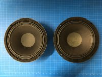
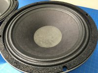
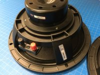
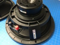
Tang Band W8-1808---SPL 93dB, Sd 220 sq. cm, Xmax 5mm, Fs 45Hz

Tang Band W5-1611SAF---SPL 90 dB, Sd 94 sq. cm, Xmax 3mm, Fs 60Hz

Markaudio Alpair 10P---SPL 90dB, Sd 88 sq. cm, Xmax 7mm, Fs 42 Hz

Tang Band W5-2143---SPL 90 dB, Sd 94 sq. cm, Xmax 2.5mm, Fs 55Hz

The drivers are listed in the chronological order in which they were purchased.

Tang Band W8-1808 (paper cone, whizzer, phase plug)
It was immediately apparent that this driver has a frequency response which rises toward the upper midrange and treble. I listened to it on axis for this test, but if I were using it regularly for recreational listening I could not listen to it on axis with any music which has much high frequency information. Off axis by 15 degrees it improves considerably and produces a sound that is smooth, detailed, and a pleasure to hear. Given the fact that it is a larger driver than the other 3 it is no surprise that it produces more bass response (with the bass boost on the receiver, quite a bit more). The character of the sound is very much the same at low and high listening levels. It was interesting to discover that the rising response on axis was not objectionable on songs that did not have much high frequency content, such as "She's Leaving Home" and "When I'm Sixty-Four". The sound on axis was very good on those.

Tang Band W5-1611SAF (polypropylene cone, phase plug)
This driver sounds somewhat dull compared to the other three. Both on and off axis the highs are not as pronounced. Other than that, it produces a nice sound that is not objectionable in any way. It is one of the two drivers that produced the least bass response. The sound really improved with the higher listening level, with the highs becoming clearer and the sound being better balanced all round. I don't know how to account for this other than that it may have been an effect of the Fletcher-Munson curve. I think it is a nice driver, but the other three produce better detail on a variety of sounds.

Markaudio Alpair 10P (glass fiber and paper cone, shallow profile)
This is a very versatile speaker. It sounds good on a variety of material and produces a wealth of detail. It's sound on axis is detailed, clear, and comfortable, with no upper midrange screeching, and the off-axis sound is essentially the same. With the bass boost it produced a bass response second only to the W8-1808. Compared to the other three, it has a slight coloration that I can only describe as an "Aw" sound, as though someone were speaking through cupped hands. I suspect some lower midrange resonance is responsible for that coloration. The sound at the lower level was clearer than the sound at the higher level, which by comparison had a "congested" quality, sounding like too much emphasis in the broad midrange. I thought of this driver as the best full range speaker I had heard until I bought the next one on the list.

Tang Band W5-2143 (bamboo fiber and paper cone, phase plug)
This was the most recent full range driver about which I read and with which I was intrigued, so I decided to give it a try. I'm glad I did, because this one takes the crown as the best full range speaker I have heard. Compared to the other three, the impression I received as I listened was similar to that of a good pair of headphones. Smooth yet detailed, with no part of the audio spectrum objectionably pronounced, clear and warm but not bloated or congested, it sounds the best on the widest variety of material. Though the bass response with the bass boost was probably the least of all four, the tonal balance on axis was the best, and it sounds essentially the same off axis also. And, though it may seem to be a logical incongruity, the sound at the higher level was the same, only better. I really like this speaker.

I think each of these drivers produce good sound, and I think I could be content with any one of them if I were limited to using only one. Each has its individual strengths and weaknesses, and I hope to use each one in a way that will maximize its strengths while minimizing its weaknesses. These are my decisions regarding these drivers:

Though the W8-1808 is the only one I would consider using as a true solo full range driver (in a bass reflex cabinet), it will see duty in a sealed box FAST construction with a bass driver providing the low end. I will listen to it mainly off axis.

The W5-1611SAF I will use mounted in a bass reflex box as a utility speaker for the garage or an ambient speaker elsewhere.

The Alpair 10P will be used in an open baffle FAST construction with woofers on the same open baffle.

The W5-2143 will be used in yet another FAST construction which will be meant for close field (one meter or less) listening.

Please keep in mind that I am a music lover and not a speaker builder by profession or long experience. The number of speaker drivers I have heard and evaluated is not that of many members on this forum, so I offer my opinions with that qualifier. These opinions are valid for my preferences, and, I repeat, I don't expect anyone to agree with my opinions or share my preferences.

Rockville RX Md3

I have a Rockville RX MD3 thats heating up the rail caps which leads me to believe there is a drive problem.

I have isolated the current draw to the audio section.

Does anyone have a diagram of the driverboard in the audio section as I am unfamiliar with this one. Is there any other amps that are similar to this one i can scavenge some posts or diagrams to get me started?

KTA1504 and equivalent I dont have in stock. Ive seen them replaced in the power section with MMBTA56 but not sure if these would work in the audio section.

Attachments

  • 20201103_115937.jpg
    20201103_115937.jpg
    936.5 KB · Views: 122
  • 20201103_115939.jpg
    20201103_115939.jpg
    894.8 KB · Views: 130

FS: Set of two Jantzen Alumen Z-Cap 8.2uF 100V Crossover capacitors

I have a couple of Jantzen Alumen Z-Caps for sale, purchased for a crossover upgrade that I ended up not doing.

They are previously used, but in good shape and test fine.

Asking $60 USD for both + shipping. I'm in Canada, should be about $15 USD for North America, or about $20 elsewhere.

Edit: SOLD!

Attachments

  • IMG_6755.jpg
    IMG_6755.jpg
    964.5 KB · Views: 166

Simple Tube Preamp 60 second Mute - why wouldn't this work perfectly?

OK, go easy on me please... need advice before I do something stupid...

Looking to add a 60 second delay the simple way (I know there are many timer circuits, but this seems like a slap in and forget for cheap)

SQUARE D 9050JCK13V20

Pros
Heavy Duty contacts - Octal base - DPDT - 120VAC Coil - timer dial range .6 to 60 seconds

See attached - 120VAC on Pin 2-7 activates 60 second relay - Left / Right channel outs to pins 1 / 8, ground on 4 / 5, final Preamp outs on pin 3 / 6.

Can this be as simple as this for less that $15 (Used)?
Since 120VAC, dangerous? Better sticking with lesser voltages?

Attachments

  • s-l1600.jpg
    s-l1600.jpg
    138.8 KB · Views: 198

Homespun Tools for Audio

I just made some handy tools today and thought I'd share, I would imagine others here have knocked up their own tools specifically for audio work and if you wanted to share in this thread, I'm all for it.

What I made were hand tools for Potentiometer / rotary selector nuts. I often use deep sockets, or longnose pliers, but neither are especially easy to use for this job - pliers can slip, and with a deep socket the nut tends to disappear up the hole especialy when trying to reinstall it.

So I cranked up Fusion 360 and designed a driver specifically for the task, scaled for 11mm and 12mm, "hit print" and voila.

They work a treat for the job. As the deep recess is enough for the shaft (it's 9mm diameter) but not the nut, it's easy to reinstall.

One thing which occured to me after, space for a small magnet (to the side of the recess) would be great for retrieving the nut and washer. I might give that a go in revision 2. Another idea is a hex nut up top, for those times "additional encouragement" is needed, but I don't know just how much one of these will take before it breaks (only one way to find out, I guess) and at that point it's probably time for the big guns anyway.

If anyone wants the .stl files to print their own (for personal use only, please) drop me a PM. One I printed in PETG, the other PLA, with 1.6mm walls (the shaft of the tool is essentially solid aside from the recess). They seem sturdy enough.

IMG_20201027_175641.jpg IMG_20201027_175650.jpg
888022d1603785108-homespun-tools-audio-img_20201027_181516-jpg

Rattling Ports?

My sub rattles - badly. It's not the driver. I don't think it's the cabinet. Could it be the ports?

If I block one port the vibration is reduced by 80%.

If I block both ports the vibration is reduced by 90%.

If I remove both ports and turn the cabinet on its side ( so the holes are sealed by the carpeted floor) the rattling vanishes.

My ports are similar to these but with a small flare on the internal end.

I'm stumped.

port.jpg

Inifinite Baffle

I am building a new home, and will have a dedicated media room approximately, 22' L x 18' W x 9' H.

I have a pair of Theil Smartsub 1.12 drivers I bought at their liquidation auction, and was considering building new enclosures, but was wondering if anyone has had any luck with IB's. I am going to build an interior wall 2 feet from the basement wall for my screen, and was thinking this might be a good area to put the subs.


The space would be approximately 2'dx18'wx9'h.

Any ideas, comments, or reference material would be appreciated.

Nakamichi remote signals

Hi,

I study the schmatics of the Nakamichi RM-300 Remote control, which is the original wired RC for the Nakamichi 1000ZXL.

Its schematics is provided in page 99 of the 1000ZXL Service Manual, and is herebelow:
201105100141735772.jpg
[/URL][/IMG]

On this schematics, it appears that the pins 2 and 4 of the RAMM DIN connector (see upper right) carry information coming from the 1000ZXL to the Integrated circuit IC-001 (this info should be used to display the counter value on the RC counter).

I try to know how this information is formatted from the tapedeck ? is there a modern integrated circuit that could read this information ?

To date, nobody knows...

Thank you

What insulation material between PCB and chassis?

Hi guys,

What type of insulation material do people use between a PCB and a metal chassis.
I know stand offs are used as a spacer underneath offering protection, but what can be used on top or below, as I often see in commercial products a type of hard card.
The reason for asking is my current project fits very tightly into its chassis.
Thanks in advance.

Karlson FR/Tweeter fun with a 3" LaVoce and cardboard lens

IMO. a K-tweeter for a little cone can work well with a shallow tapered chamber and thus something like a miniature K15 vs a klam arrangement. (One can certainly try both and I've not worked with the mini-klam enough to pass judgement)

A strong on-axis rise is highly desirable for acceptable result. The 3" LaVoce
I picked has about the strongest seen for that size and little money. Its a very well made driver too.

Anyhow, one might make a fullrange "flooder" of sorts with driver facing straight up and lens set on top. My cardboard cabinet has a couple feet of expansion, then choked at terminus, "balloons" from pressure. A more proper rear load and construction should help.

With an oval slot lens, sound was strident - with this happenstance K-lens, things are quite holographic with sounds such as fireplace "sparks" alive pretty far off axis.

It could be used with small back chamber as a tweeter.

LaVoce FSF030.70 3" Ferrite Full-Range Woofer 8 Ohm


BvJVDPh.jpg

xgN8w6w.jpg

MdZBWhU.jpg

xoeciEQ.jpg

Random maker-type dipping toes into the water

Hi all.

I've been bumping around looking at various amp and speaker DIY sites for a while now so I figured I should sign in. I might be the worse type of noob; I trained as a EE, teach high school science, and ran a FIRST robotics team for many years. In other words I have just enough knowledge to nod along at all the right places but none of the experience to actually move into the expert category!

My short term goal is to build what is more or less a more complicated computer speaker. Mono speaker with a tube amp built in to run from either the headphone jack of a phone or computer or, as a second step probably, from a bluetooth connection. I'm not much of an audiophile - the project journey is the most interesting part although getting something to use while working on other things will be a nice side benefit.

Expect to be plagued with questions about a very fringe use of tubes!

Class AB amplifiers with Switch Mode Power Supplies?

Hello All,

I have a question about power supplies for our old-time favorite Class AB amplifiers.

I have lately measured the THD+N of several amplifiers. Many, most if not all have with Full Wave diode bridge plus Capacitors even including inductors the power supply noise, you know the 50 or 60 Hz series, 60Hz, 120Hz, 180Hz and on up, of diodes turning on and off spikes dominate the THD+N figure. The power supply spikes are higher dB’s than the 3rd, 4th and 5th harmonics sometimes.

Switch mode power supplies in Class D amplifiers are quieter than the previous generation.

The question: Has anyone or does anyone use switch mode power supplies in old school Class AB amplifiers?

Just for grins here is a sample of a well behaved Full Wave diode bridge power supply in a NAD amplifier. I replaced with new the protection relay and all of the PS capacitors. Plus a not so well behaved example.

Thanks DT

Attachments

  • NAD 216THX FFT.png
    NAD 216THX FFT.png
    67.4 KB · Views: 749
  • FFT Parasound Zamp v.3 5Watts at 8R.PNG
    FFT Parasound Zamp v.3 5Watts at 8R.PNG
    70.6 KB · Views: 729

Measured data on the J105 Nchannel JFET

I've gotten interested in using the JFET-NPN hybrid Darlington connection shown in Figure 1 below. While a standard Darlington has an emitter follower which drives another emitter follower, this circuit has a JFET source follower which drives an emitter follower.

I think I'd like to try the "J105" device in this circuit, and as luck would have it, I bought 100 of them back in August of 2014. I keep a little snip of the shipping bag in my parts drawer, to remind me where and when I bought these units. The J105s came from DigiKey: Figure 2.

So I chose twelve J105 units at random, and put them on the curve tracer. I plotted IDS (vertical axis) against VGS (horizontal axis) with VDS held constant at 10 volts. The slope of this curve is d(Ids)/d(Vgs) which has a special name in circuit design: transconductance. Often written "gm".

The measured data is shown in Figure 3. There's quite a spread in the data!

Simplistic mathematical models of JFET behavior suggest that IDS = Param1 * (VGS - Param2)**2 where Param1 is a gain factor related to the JFET's channel width and length, and Param2 is the "Pinchoff Voltage". "**2" means raised to the power 2, i.e, squared. The data in Figure 3 suggests that the spread of Pinchoff Voltage for these twelve J105s, is about 700 millivolts.

To see this, draw a horizontal line at IDS= 50 milliamps. It intersects the leftmost J105 curve at VGS= -5.7 volts, and it intersects the rightmost J105 curve at VGS= -5.0 volts. A spread of 0.7 volts (!).

If a (very small) sample of just 12 parts, gives a spread of 700 millivolts, I imagine that a larger sample will give a much bigger spread. I hope to measure many more J105s in the coming days, and find the very leftmost curve, and the very rightmost curve. These represent the extremes of the sample and, I hope, they may approximate the extremes of the population of all J105s ever built and sold.

If by some miracle I can find SPICE model parameters which fit these two extreme transistors, then I can simulate circuits using the "best" J105 ever built and also the "worst" J105 ever built. If my circuit design works acceptably with both extremes of J105 then I can feel confident it will probably work acceptably with average J105s that are not so extreme. That's the hope.

Fairchild's datasheet is also attached.

_

Attachments

  • SF_EF.png
    SF_EF.png
    47.8 KB · Views: 1,049
  • DigiKey_Bag_J105.jpg
    DigiKey_Bag_J105.jpg
    71.6 KB · Views: 1,026
  • J105_12units_IDS_VGS_at_VDS_10p0.PNG
    J105_12units_IDS_VGS_at_VDS_10p0.PNG
    57.6 KB · Views: 1,012
  • J105_datasheet_Fairchild.pdf
    J105_datasheet_Fairchild.pdf
    419.6 KB · Views: 138

Phoenix Gold MS-275 distorted output

Hi I'm new here, I'm from Italy 🙂, sorry for my bad english.

I have a PG MS-275, unfortunately it have distorted output sound from the two channel.
Two of the four red led are lightly on and the other two are working fine.
I change the caps and check all the transistor but I can't find any problem, also my external power supply is good.
I try also with another pair of woofer but the problem is still there.

The distorted sound occurs more when the music have bass so I think it's something relate with power but I don't know what it can be.

You have any advice?

Thank you!😀

Source for dual 3.5mm mono jacks?

Despite my extensive google'ing (Newark, Mouser, DigiKey, etc), I can't seem to locate a source for paired 3.5mm mono panel mount jacks such as:

DSuGPOr.jpg


The only ones I've found appear to be intended for direct PC board mounting. I need either solder lugs or socketed like this one:

ZoKF1cK.jpg


This would be used for the 12v trigger(s) in a (hopefully) simple ICEpower'ed amp I'll be assembling.

Suggestions would be much appreciated.

Single power source for 2 chip amps

I'm trying to put together a small, inexpensive setup for mocking up/testing bi-amped 2 way speaker builds. The plan is to use a MiniDSP as an active XO/EQ and send the split signals to 2 chip amps like the ZK-1002L or even raw Tpa3116d2 or tpa3255. I want to put the amps in a single small chassis with a single power supply to run them both, rather than having to use 2 wall wart or brick power adapters with their own cords. Is there a simple plug and play option to suit my needs? I'd rather not build a PSU from scratch. Minimum specs to hit my power needs is 15v 2a but the amps can take up to 24v 5a I believe. I have tried googling dual output power supplies and browsing places like Mouser but I'm really not sure what I'm looking for. Any advice a/o part recommendations would be much appreciated.

Feedback and Gain

Hello everyone, is there a 'simple' way to calculate gain changes with alterations in a feedback circuit?

I have an old Sp8 circuit that takes feedback from through two resistors, one of which is optional to remove for a 10 dB alteration according to the manual. I was wondering if I could reduce by a little less e.g. 5 dB by altering this resistor as opposed to removal.

ARCDB is here (last 3 pages are the circuit I have) and there is a note 5. on the circuit diagram about resistor R27 removal for 10 dB gain.

I have also interpreted that more feedback = worse sound, so want to be careful about how much to temper a very high gain preamp with very sensitive speakers. (It still hums a little too much on standby, and I don't use much of the volume know for full listening levels)

Thanks

B+ & B- toroidal power - noise question (PSRR) for tube amps

I think this is more a power question hence here.

Tube amplifier with B+ and B- from the same PSU, I assume that if we have PSU noise then it would occur on both B+ and B-, thus using both in a push-pull means the output has +noise and -noise along with the signals amplified and therefore cancelling out?

I've not seen this done as much in pre-amp stages from a lot of the schematics - is there any reason for this?

Possible ported enclosure for Panasonic EAS/Matsushita drivers

Hi All,

I have 2 pairs of 16cm EAS / Matsushita drivers that have been sitting on a shelf in my garage for at least a decade. One pair was pulled from some Panasonic speakers like these that I got from Goodwill for like $5.00 but that had cracked plastic housings:

Vintage PANASONIC SB-84 BARREL SPEAKERS MID CENTURY MODERN HI-FI GEAR JAPAN Cool | eBay

I'm not sure where I got the other pair, but probably from another pair of Panasonic speakers.

I recently listened to them in open baffle and found they didn't sound bad at all.
I'm sure these are high Q drivers but, I was wondering if I could do a ported enclosure for them. Something that might get down to 80-70hz.

R/
Jim

Influence of output impedance upon the speaker's resonance

This is speed response of a speaker (Satori MR16) by a 0 impedance generator.

attachment.php


This is the output impedance of APEX AX6.
attachment.php


attachment.php


You can notice that at low frequencies the impedance is negative, I wondered How it can influence upon the speaker. Here is it, notice the phase shift.

attachment.php

pressure response with generator
attachment.php

pressure response with apex ax6
attachment.php

Attachments

  • apex6.2.jpg
    apex6.2.jpg
    47.6 KB · Views: 482
  • imp apex.jpg
    imp apex.jpg
    58.6 KB · Views: 524
  • APEX AX6.JPG
    APEX AX6.JPG
    58.4 KB · Views: 593
  • apexax6.jpg
    apexax6.jpg
    52.2 KB · Views: 494
  • alone.jpg
    alone.jpg
    49.6 KB · Views: 469
  • with apex.jpg
    with apex.jpg
    50.9 KB · Views: 467

OB experimenting driver suggestions?

Hey all, after a many year break from building speakers, i had a listen to my neighbor's setup (not DIY, pair of Pure Audio Project open baffles with a beyma AMT tweeter and dual Morel 10" woofers) and i've caught the bug again, hard... And after listening to some Mono records being played on a pair of speakers and falling in love, i'm going to build a mono speaker to see what it's like.

I've never experimented with full-range drivers before and decided that's where i'm gonna start this time. So was just wanting to fish for some recommendations on drivers to start with/look at.

Going to go OB. Would love to do everything >250hz with a full range driver. But can't decide if i should go 3 or 4" full range and try to get it down to 250hz-ish and cross to bigger driver to get me down to 100hz or so where i'd then cross to dipole W-frames (because i've never tried an W frame and want to try it). OR if I should just go for a 8" full range and run it as low as i can get away with, cross to the W-frames where i can get away with it.

So I'm looking for A) some ideas of full range drivers to consider B) what do you guys think small full range or big?

Also, i'm willing to spend up to about $150 for the main full range driver, but i personally get a lot of satisfaction from using budget parts (the thought of using a Fostex FF85WK for <$50 makes me happy but it's unclear to me how low i can run it)

Oh, and everything will be active with crossovers and any EQ applied via an older minidsp 2x4. My listening tastes are mainly jazz and acoustic music.

thanks a bunch in advance for any ideas, comments, or suggestions!!

SPL Dynamicss-1200D PS Trouble

I received this amp. The owner connected a sub with lower impedance, the amp draws current and switched off.. I want to test the amp, but its not switching on.


On the PS Driver Board is a Jumper, seems like undervoltage release. If i switch that jumper , the amp turns on. Does anybody have a diagram for this. Iam sure, that there was something in the forum, but i cant find it.

Attachments

  • Screenshot_2020-11-05 SPL Dynamics S1200D - AMP-Performance.png
    Screenshot_2020-11-05 SPL Dynamics S1200D - AMP-Performance.png
    974.4 KB · Views: 109

Carver M400 PSU Repair

I picked up a Carver M400 cube the other day. it was blowing fuses. Found a service manual online that is very detailed! following the steps in the manual i found out it had a blown Bridge rectifier for the 25V supply, got that repaired and now i can get it to the point where i raise the voltage on a variac and the triac starts to fire but it is running very rough. looks like the triac is not firing correctly. from what i gather in the SM that at idle I should only see half of each sine wave. that the triac should be cutting off at the peak of each. and what im seeing looks more like a full sine with a glitch around crossover every other sine and the transformer ticks.

changing the triac made no difference so i am assuming that the diac is bad. I cant get it past 60% of line voltage without it drawing lots of current. and adjusting the firing control pot on the PSU board doesn't seem to do anything which i figure is probably normal at this point.

I'm curious why i couldn't use a standard light dimmer adjusted to half sine to fire the transformer just for testing? there wouldn't be any regulation but I could at least test to see if the rest of the amp comes up and runs long enough to verify the problem is in the triac control section. Looking at the schematic that's all this PSU is, is a light dimmer circuit. same exact circuit with the exception of an LDR in place of the pot.


Zc

FS: Tesla P-1011 tonearm

Anyone interested in a tesla P-1011 tonearm ? It was removed from a broken Lenco L450 turntable and has been sleeping in a box for years.

Some data: Tesla P 1101 Manual - Stereo Tonearm - Vinyl Engine

It's in good shape except for two points to fix:
- the outgoing lead is quite short; it probably would be necessary to rewire it.
- one of the small leads on the headshell has lost its connector. They're quite old, it might not be a bad idea to change all the small leads anyway.

The small counterweight isn't on the pics but is of course included too.

Just make me an offer, shipping at cost from Belgium.

630412d1502801377-fs-tesla-p1011-tonearm-img_20170815_141125307-jpg


630411d1502801377-fs-tesla-p1011-tonearm-img_20170815_141143724-jpg

VU (PPM) Meter ONKYO M-5060

Guys,
I really like the way the Onkyo meters work. Fast and sharp response. These meters are the best that I ever seen so far. This is why I decided to build circuit based on this design. Obviously is not only the circuit to ensure this performance but also the meters! I hope you can help me determining the proper meters available on the market. I have TA7318 so I'll try to build similar circuit. (Original schematic attached)
First I am trying to understand how the circuit works and I have coupe of questions that I hope you guys can help me.
1. MJM4558. on the schematic it shows they are running at +21V/-21V.
Why? the data sheet says maximum voltage is +/-18V.
2. Diodes, D1006 & D1008. they are used here to prevent deflection of the
meters after power up. They are then bypassed by the relay that is driven
by the protection circuit. D1006 is 15V zener. Based on the 21V supply at t
the output of the Q1006 the voltage is above zener where the diode starts
conducting so the meter deflection must occur.
3. Q1005, what is the purpose of this transistor? It seems to be
protection from meter moving when the speakers are still off. I don't
understand, the base is driven by the lamp driver. The lamp driver is
driven by the same protection circuit that also drives the relay to bypass
the diodes mentioned above.
To turn of the transistor the base is driven negative -3.6V. which is
impossible it rather be - 0.6V. How could the measure -3.6. I know the
resistors R1047 & R1048 make a voltage divider and will give -3.6V but
only if the transistor is not there. Besides the collector when the protection
circuit is hight so supposingly it should fully turn on the transistor but it
remains floating so the signal will flow from the Q1003 anyway and not
protecting the meter from moving...

Attachments

  • Screen Shot 2020-11-01 at 4.10.10 pm.jpg
    Screen Shot 2020-11-01 at 4.10.10 pm.jpg
    466.8 KB · Views: 444

Marantz PM7200 Can't adjust Idle Current or DC Offset

Thanks for reading me:

After i repaired the speaker protection board of that amplifier, all was ok.

So I then proceeded to adjust iddle current, got it, then DC offset. Oh, bboy.

At that stage, on the left channel, after first seeing normal readings while moving the trimpot to get to the correct setting, suddenly readings were all over the place and did not respond to my turning the trimpot.

I played music to earphones, to find that there was no sound on left channel. Only distorted crackles on peaks.

I took out the board and took out the trim pot, measured it as being ok from end to end and from the moving wiper. Cleaned it anyway and retested as OK.

And, i resoldered 7265 that had broken solder joints. That component was probably the one acting up (relays clicking) when i pushed away the supply wires (touching 7265?) to have access to the trimpot. (BTW why do these (TO126?) stand so high on their legs, wrapped in shrink tubing??) I also reflowed the connector for the supply lines, just to be sure.

I reinstalled the board. The audio is now heard on left channel. Distortion is hard to qualify on cheap earphones and with my old ears and in haste not to blow anything up.

But: i can't adjust either Iddle Current (.2mv) or DC Offset (160mv). Trim pots have no effect. With power off i rechecked that DC offset trimpot and it was still behaving correctly.

I probed the supply lines as deep as i could, including around some transistors (results i should not quote now, but maybe of interest: 7261 is E 53.2V, B -52.7V, E -53V). All seemed normal in my limited understanding of those circuits. I tested in circuit the first components branching out of + and -VB, and double diode tested 7265. I did not probe under the copper shield (housing 7251, 7253, 7255, 7257, 7259) yet.

I hope there is an obvious "classic case" component causing that anomaly, which some knowledgable and experienced person here will point out to me.

I saw that i can easily unsolder that copper shield and probe those components. If someone points me to what i should measure there?

BTW all i have is a digital multimeter. It can test semiconductors. It also has capacitance capability but seems unable to measure >20?uf . To find good units in my NOS stash i rely on reading DC volts, discharge, remeasure DC volts, do long Ohms test, and remeasure DC volts to see if it went up. Served me well to date ;-)

So with that multimeter, can i test transistors IN circuit with the double diode test? i'm afraid to kill them with heat from the iron, but will manage a heat sink (like, my wife will hold the longnose pliers ;-)) if necessary.

Thank you all for your insights and help.

service manual:
https://www.hifiengine.com/hfe_downloads/index.php?marantz/marantz_pm7200_service.pdf /url

SB17CAC burned in : any T&S .frd .zma please?

Hi,
Has anyone worked with the SB17CAC35-8 (or-4) and measured the T&S after few months of use or a strong burning in, please ? Any .frd and .zma known please?

I saw measurments by Audioexcite of the NBAC and the T&S parameters seems to move a lot after burning in vs the datasheet. Would like to know how the CAC version compare in the low end for a small cabinet and if a strong BSC is needed...


Many thanks if any feedback, datas,

Slimline 3U question

I'm working on a project that I'm hoping to use the Slimline 3U chassis in the 350mm size (aluminum panels). I would like to find out the position of the vent slots in the bottom panel so I can plan mounting positions of PCB boards, transformers, etc.

The CAD drawings on the Modushop website don't match the Slimline 2U 280mm chassis that I recently got, so I'm assuming that some changes have been made to the design.

Are the slots on the 3U 350mm chassis baseplate the same as the 2U 280mm, regarding the size and position of the slots relative to the back of the enclosure? If so, I can take measurements off the panel that I have.

Thanks.

which will record better on PC

I have SOTA turntable & Mcintosh C34V pre amplifier. I too have Creative Sound Blaster xfi XD sound unit.
I want to record my songs played through turntable.
is it good to use Mcintosh as preamplifier for MM cartridge then to connect to line input of PC. or use Sound Blaster xfi XD for MM cartridge and directly record in pc.
what will have better recording quality.

Thanks in advance for Guidance.

20 years later, time for a new kit?

Back around aught-one I built a set of the full range Adire Audio MTM kits. Bang-for-the-buck is off the charts, but lately I've had a case of the wandering ear. Their bass response is boy-scout honest, and imaging is decent. I find music passages with loud vocals or brass to be a bit harsh. Jazz, bluegrass and rock are the majority of my listening but few genres are ignored.

Since we can't go to live shows these days, I'd love to recreate as much of the experience as I can at home. I have a fairly small room as my listening space, so giant horn-loaded klipsch-esque rigs are off-limits.

I'm not clever enough to design a speaker but I am a recovering professional cabinetmaker, so the woodworking is second-nature to me. Please let me know if you have any recommendations for kits or plans.

Anti-Vibration Feet

I'd like to find out the dimensions of the Anti-Vibration feet that are offered in the DIYAudio Store. I did a search and could not find any specific information.

What is the diameter and height of the footers (not including the stud)? How long is the stud above the footer? How large a hole is required for the stud?

I want to make sure the footer mounting studs will not interfere with components that I am planning to install in the chassis.

Thanks.

Will this work? Or is it going to suck?

Hi!

I was in the loft recently and I found an old Block Rocker IPA006 by ION. To be honest, the sound always sucked. It was never a Hifi unit, but had a long run time and sound that reached well at garden parties / halls etc. Think 'mobile back of bike' units that people build, but without decent sound 😉 We're talking more than 10 years ago before a lot of the newer lithium powered units like the inter-connectable JBLs. Whilst in the loft, I also came across a couple of Vibe Slick 69.2's. The whole lot is destined for the tip unless I can do something with it. So I got thinking: Could I improve the original block rocker so that it doesn't suck and can once again be useful?

The only real aim here is low cost or I may as well go and buy newer Bluetooth inter-connectable units from [insert manufacturer name here].

The existing circuitry is junk. It's got a transformer for mains and a redundant 30 pin iPod dock. As for the speakers, it looks like a mono setup with a mediocre tweeter and 8" sub. There is a mic input which was handy.

The battery used Huanyu HYS1250 (12v 5Ah) which gave a rather impressive run time of about 12 hours.

My brainstorm idea is this:

1. gut existing circuitry
2. keep sub, ditch tweeter
3. fit vibes to sides of unit (the 69.2's are 2 way)
4. fit a 12V amp such as the TPA3116
5. fit decoder unit for bluetooth/aux and mixer for mic that feed to amp
6. Use better battery (I can find a 12V 12Ah lead battery for ~£20)

So layout is:

Decoder > Mixer > Amp > Left (Vibe 1), Lows (Sub), Right (Vibe 2)

I've been looking around on net and various sources seem to suggest that using car audio is a no go, and that a PA speaker is the way to go, although this would incur extra cost. I suspect the Vibes may be too higher wattage (RMS 135 / Peak 400) for a small amp like the TPA3116?

Questions that you good people might be able to answer:

1. Is this flogging a dead horse? Are the Vibes a bad idea? It's only because they're here and free that I have even considered this.
2. I have read that the TPA3116 ideally needs 24v or it will suck.. this is going to double the cost of the batteries if so and make a possible later internal charging solution more complex. Does anyone have any experience with this at 12v? Or is there a better alternative?
3. Is this all just a crap idea and would I be better off with a PA speaker?

Any and all other input/help/advice is welcome!

Ta Chaps and Chapesses 🙂

Hitachi HMA-7500 Idle current issue

Hi guys,

I'm recapping a Hitachi for a friend. The amplifier was working fine so I took it on. After recap I went to adjust and found the old bias pots are faulty so I replaced them. But now although the bias has dropped from 330ma to around 170ma. The service manual states 200ma.

The problem is when I adjust it, it doesn't make any difference! I checked a few resistors around the pot and a few Zener diodes and they are fine.

Any advice would be greatly appreciated.

Attachments

  • hitachi1.jpg
    hitachi1.jpg
    430.9 KB · Views: 407
  • hitachi2.jpg
    hitachi2.jpg
    484.9 KB · Views: 462

LT spice - how to prevent saving RAW and FFT files

Anyone know if I can prevent LT spice saving RAW, FFT, and TXT files?
When opening folders with the ASC files, there are many huge RAW and FFT files laying there. Is there a way to stop saving those? I have tried going to the save default window and checked off (and on) the various options.
I know it was possible in previous versions. Has this option been taken away on version XVII?
Thnx

What are these burnt element pcb hifonics goliath gx5000d

It is a board that controls the output transistors, the symbols are worn and it tries to find what it is, if someone knew I would be grateful for any suggestions. It is a 14-knife smd integrated circuit

Attachments

  • IMG_20201105_175031.jpg
    IMG_20201105_175031.jpg
    458.3 KB · Views: 122
  • IMG_20201105_105730.jpg
    IMG_20201105_105730.jpg
    594.4 KB · Views: 111
  • IMG_20201105_105727.jpg
    IMG_20201105_105727.jpg
    714.2 KB · Views: 119

Late to scene, is there?

Ok, I ripped my entire CD collection onto an SSD, bought a windows touch screen PC and with only Windows Media Server, have a pretty good server. Of course, it goes to a USB DAC, then to an analog preamp, analog crossover and analog amps. Adding a few SSRs so when the PC powers up, so does everything else. The "boss" demands it to be easy and intuitive.

I do still have a very good CD player that is convenient ( PCM out) and a analog line from my cable box for background music. Easy to make both into USB.

I found a pretty nice PC based equalizer.

What I do not find is a well integrated "preamp" application to tie things together as easily as my analog preamp. Simple touch screen buttons for source and volume. Then buttons to get to the EQ, crossover, and output routing setup. I do not see any particular reason this could not be done. Don't need BT, phones or stuff, but I gather some would.

If such an app existed, I would only need the PC and a DAC for each amp.

Actually, we need a protocol and format to feed the digital stream right to the PWM stage of the power amps bypassing yet another D2A/A2D stage but that is a different question.

Function generator transformer problem

I bought a Thurlby Thandar TG210 function generator from Ebay for £10 a while ago which worked fine until yesterday. After turning it on, it developed a loud buzzing accompanied by a distinctive smell. I opened it up and the smell comes from the transformer, it's not a burning smell as such.


Is it worth replacing the transformer, or will this have damaged the circuits?

Attachments

  • inside.jpg
    inside.jpg
    992.2 KB · Views: 120

Hacked Google home mini to have a line out - weird ground noise issue when no sound.

Hi All,


This is actually my second thread on this. My original one was in Class D, but I know it's more related to some sort of line level issue and thought I might get better help in here.


I followed a tutorial to put a line out on a Google home mini which I am feeding into a class D amplifier board based off a TPA3116. This works brilliantly when there's audio coming from the Google home mini.


The "hack" is basically removing the speaker and putting a resistive divider on it's output to bring the speaker level output down to line level.


However, when the home mini shuts down the audio output as it's not doing anything (I'm assuming it turns off the amplifier to save power when not in use) I get a horrible ground noise hum.


I'm not sure how to tackle this. Someone in the other thread recommended putting a NE5532 preamp between the Google home mini output and the amplifier input. I tried this and it made no difference.


Has anyone any ideas? I'll try anything as I'm getting a bit desperate at this stage.

The amplifier is one of these if it matters:
789446d1571733035-6-channel-tpa3116-dsp-aiyima-tpa3116-amplifier-audio-board-5-1-channel-digital-power-amplifier-board-50w-4-100w-2-jpg


Thanks

Best audio power MOSFET

Hi,

I want to know what is the selection of high power mosfet (N channel) for audio amplifier purpose. Currently I use 2sk 3911 (Toshiba), seems it has high spec (600V, 20A), but very high input capacitance (around 4nF).

Considering another kind of MOSFET to get more clear, nice sound of my DIY power amp, or just to parallel the same mosfet to get more damping factor?

Some mosfet available e.g. IRFP 240 (popular), 2sk 1058 (also popular) etc. The original design is using IRFP 350 hexfet. There are some other mosfets available in my local market (not remember).

Thanks,

Ervin L

Big Mouth Strikes Again

I currently have four 3D printers, and every one of them is failing in one way or another.

Out of frustration, I decided to dust off my K40 laser cutter and try making something.

The idea with this project is to make a Unity horn that has pattern control down to about 500Hz, same as the Danley SH50.

I don't see any scenario where my life allows an SH50 in our living room, so what I did with this project is limit the depth dramatically. The idea I had, is that I can achieve a look that's similar to a Quad ESL if I keep the depth down to a minimum.

YJx86UA.jpg


Here's what a Quad looks like, I'm trying for a look like this.

IZBPG8H.jpg


7UkQW5T.jpg


OCpsu9r.jpg


fp1opJc.jpg


tkLTdbk.jpg


tCnW30e.jpg


All the pieces of the waveguide are laser cut. I used hot melt glue to hold it together long enough to fiberglass some of it. Then added foam to make it sturdier. It will require a lot more fiberglass and more foam to make it ready for prime time.

Also, don't mind the weird Halloween decorations, the kids did that. And no, that roach isn't real 😛

Discover the output capacity of PC linear power supply

I hope I am asking the question in the right forum. I bought recently a second hand audiophile server made by a small Dutch company. I do not have documentation but I could identify immediately that they are of very good quality. The server uses a Jetway embedded low power mini ITX board and a custom-made linear power supply with a toroidal transformer.

As the current CPU is not very recent, my idea would be to upgrade this part of the system in the future. The issue I have is that I don't know if I can go towards a higher power Mobo/CPU. I managed to identify the transformer and it is a 120va 2x12V.

I am new to this stuff and trying to learn, but is there a way I can identify the maximum load the power supply can provide. The current CPU is a Celeron 10W TDP.

May I share my Zen 4

Hello,

I have just finished my Zen4 amplifier and just wanna share it here. 😀

It work with 2 tyrannies as dual mono amplifier, force cooling by low noise fan with tunnel heatsink.

Sound great. It can push my ATC scm11 with the good tonal in mid and high, bass is acceptable. of course I cannot play it very loud, but at my listening level it perform quite good.

Now, I looking for matching preamp. Any suggestion? Should I go for Aleph P? or BZLS? to be not over kill for the power amp.

Big thank to Nelson for his great sharing.

b5F4Pt.jpg


b5FNee.jpg


b5Ff3l.jpg


b5Fhbk.jpg


b5Fkav.jpg


b5F94E.jpg


b5FTQN.jpg


b5FtnV.jpg


b5F1dQ.jpg


b5FKZS.jpg


b5FZPn.jpg


b5Fcmg.jpg

High power single supply amplifiers?

I have started construction of a 6 channel battery powered system (16S, 20Ah lithium ion) and have some TPA3251 based amplifiers from 3e audio on the way as a starting point. A buck converter is used between the battery and the amps to supply their 36V supply.

If this works out well though its likely that I would want considerably more power for subs than the TPA3251 can supply, I am aware of the TPA3255 which would run off a 51V supply (it was out of stock and has higher idle power consumption so I decided to go with the TPA3251 for now), what options are available for higher powered single supply amplifier modules?

I looked at sure electronics/wondom and their higher powered modules (up to 3000W) all seemed to require split supplies.

I'm not interested in amplifiers that can drive ultra low impedance to get their power rating (typical car audio amplifier) as pro audio drivers are only available in 8 or 4 ohms so to get good volumetric efficiency from the system the amplifier should develop maximum power into 4 ohm.
Projects by fanatics, for fanatics
Get answers and advice for everyone wanting to learn the art of audio.
Join the Community
507,774
Members
7,888,010
Messages

Filter

Forum Statistics

Threads
406,214
Messages
7,888,010
Members
507,774
Latest member
pete2000