Two way plastic sphere + PVC pipe mixed ML-TL

Hi guys,

I wonder if it has been done, and what would happen if for a 2 way, the midbass driver is placed into a sphere of known volume and then two PVC pipes are supposedly interconnected into the sphere. One PVC pipe will be closed, the other will have a port to mass load the TL. The main ideas are:

-simple materials to experiment with.
-two pipes, one will serve as the speaker offset to kill the closest harmonic
-street lamp plastic sphere as the primary driver enclosure to reduce back radiation of waves towards the cone. P.S I need to check the BSC frequency with spherical enclosures.

The fullrange speaker can then be mounted inside a second sphere, where a "pseudo Nautulus" can be built, a sphere with a pipe opening and aperiodical stuffing.

What do you think of this idea?

Supply Filter Capacitor

I know a person who once got into a debate with me about choosing the value of amplifier's power supply filter capacitors.
I told him that supply filter cap's value are chosen according to the amount of current it should filter. But, from his point of view, the more the capacity the better the sound quality from every aspect like low, mid and highs are touching the sky.
Anyway, I know that supply filter cap's value make a difference in sound quality. But according to logic/physics, is there a point where this theory becomes useless?

Amplification for Carmody's Amigas MT speakers?

Hi all,

I am in the process of building a pair of these: Amiga - undefinition from a PartsExpress kit. These are 8Ohm, 83/84dB according to Carmody himself.

I plan on using a Raspberry PI as a streamer so no need for that feature to be necessarily integrated. I would rather a decent integrated, possibly with sub- and/or pre- outs. Can you guys make any suggestions in the $400-500 or less price range? I'm ok with factory refurbs but would prefer to avoid used market.

Another option is RaspberryPI+DAC hat, into a volume box such as a Schiit Sys, into a power amp. I think. But I don't know how I would ensure these would work together without blowing a speaker or a component...

I have been looking at, in no particular order, Cambridge Audio AXR100 refurb, Allo Volt+D, Emotiva TA-100, IOTAVX SA3 refurb, Yamaha A-S501 refurb...

If there is amore appropriate section for this post, please let me knowing I can repost there. Or feel free to move this post over.

Thank you for your advice.
G

Passive output SCR 2496

Hi there

I have put a passive output in my SCR 2496, it worked fine, but now it is very muffled nearly muted, I bougt a DIY DAC with the AKM AK4396, put a passive output in it and it also is very muffled nearly muted, i use the french article for my output change, that is a high quality cap, 6,8 µF in series, a 2,2 µF paralel and a 1k resistor direct from the AKM DAC chip, am i doing something wrong?
When i use the active stage all sounds normal.
I am no expert, but play around a lot with electronics....

thanks for information, tojoko.

Push-pull ripple rejector (by Podoliak)

I think that the ripple from power supply is responsible for at least 30% of "transistor sound". In a way to reduce ripple I have invented this push-pull schematic. I have no intentions to patent it (I already have 3 patents and never made any decent money from them). If it is new I proclaim it public domain (with my name attached to it "Podoliak").
The circuit works as follows:
1). the signal from usual rectifier -WITHOUT SMOOTHING CAPACITOR - is splitted into two regular zener-diode voltage regulator.
2). One regulator has zener-diode lifted from ground to collector - thus the bias resistor and zener diode are interchanged in one regulator. At this point the outputs of both linear regulators can be smoothed by capacitors. The voltage of zener diode(s) should be near 50% .. 55% of max amplitude of signal from rectifier.
Thus, one regulator cuts the upper half of a signal, the other - the lower half.
3). The two signals from both regulators are then summed in bipolar transistor (with high max base-emitter current limit).
4). The output can be smoothed by capacitor in a usual way.
There are two basic schematics in this concept:
= one with lower half - feed into collector of summing bipolar;
= another - lower half - feed into the base of summing bipolar.
This schematic:
a). increses the utilization of signal from rectifier.
b). provides smoothing of two near-equal signal by summing them.
At this point it is just a concept schematic, modelled in MicroCap 11 (9,10) software.

Transient -local pictures show rectifier signal, base of upper transistor, base of lower transistor.
Working title was (like in Hollywood) "push-pull rectifier".

Attachments

  • Push-Pull-001-2-Schematic.jpg
    Push-Pull-001-2-Schematic.jpg
    449.4 KB · Views: 387
  • Push-Pull-001-2-Transient-Global.jpg
    Push-Pull-001-2-Transient-Global.jpg
    310.7 KB · Views: 379
  • Push-Pull-001-2-Transient-Local.jpg
    Push-Pull-001-2-Transient-Local.jpg
    319.9 KB · Views: 349
  • Push-Pull-001-3-Schematic.jpg
    Push-Pull-001-3-Schematic.jpg
    332.1 KB · Views: 382
  • Push-Pull-001-3-Transient-Global.jpg
    Push-Pull-001-3-Transient-Global.jpg
    306.8 KB · Views: 357
  • Push-Pull-001-3-Transient-Local.jpg
    Push-Pull-001-3-Transient-Local.jpg
    327 KB · Views: 185

1000W Class D subwoofer amp for my car

Hello to all

I manage to build a excellent class D amp with 500W RMS power on 4 ohms and 1000W RMS on 2 ohms
I also build a full bridge DC to DC converter to easily driving this bad boy
everything is ok when I connect amplifier input to an external audio device like: my moble, mp3 player,.. etc
but as son as I connect the amp input to the car stereo RCA there is a huge spark and the smps current rises quickly. I guest it's because the ground of smps input and output connect togather as the car stereo and smps are powering from the same power sourse (car battery)
so whats the solution here? how does all commercials amp works then? am I missing some circuit here?

Please help me fix this amp

Creek CAS 4040 S1 schematic

I am looking for a specific CAS 4040 schematic. My creek has sn:9254. There are a lot of schematics only not for mine.

There is schematic on this forum but i can't reed the numbers. And i can't make contact with the uploader.

I need to know witch transistors are being used or witch replacements can be used. I have the folowing (i think):

Q3: ?
Q4: BFR39
Q5: BD139
Q6: BFR39
Q7: BFR79
Q8: BD909
Q9: BD910

Attachments

  • Goede schema creek 4040.gif
    Goede schema creek 4040.gif
    123.9 KB · Views: 538

Home Built Infinity SM-155

Hello Everyone!


I am kind of green still and am looking for help on building a speaker that will be the same as an Infinity SM-155.

See specifications below:

Power Rating - 10-300 Watts
Frequency Response - 29Hz to 27kHz within +/- 3dB
Crossover Frequency - 500Hz / 5500Hz
Efficiency - 102 dB SPL, 1 Watt / 1 Meter
Impedance- Compatible with 4 to 8 Ohms
Driver - 1 x 15" Woofer, 2 x 4.5" Midrange, 1 x 1" Tweeter
Dimensions - 17.75" Wide, 40.25" High, 12.5" Deep

Tone controls (mid, tweeter), auto-reset circuit breaker protection (mid & tweeter)
Port - Tuned Rear

I need help with the following:

1) driver selection
2) enclosure construction
3) crossover schematic design


It would also be great if someone with these speakers could comment on if there is bracing in the original speakers and what the port dimensions are.


Also is it possible to use a front slot port versus a rear port?


Thank you in advance!

2-way/3-way large bookself-speaker recommendations

First post on this forum and sorry if there was a sticky about recommended builds somewhere, I did not find it.

I'm looking for ideas/recommendations for a large, max 60L, bookself speaker. The size can be smaller of course, but since a big percentage of my listening is movies and series I prefer the dynamics and overall benefits of bigger speakers. I also like directive speakers (horns and such), but I'm always up for a change if there is some compelling build. Since the speaker would be a bookself the height would be limited to 60cm.

At the moment I'm using Finnish speaker designer Samu Saurama's coaxial desing. It uses Eminence CX12 woofer and Selenium D220Ti compression driver. I also have two subwoofers to deal with under 80hz frequencies. I would like to keep my crossover at 80hz or below.

Now I'm looking for a step, or two, higher in overall sound quality. Samu's newest design using B&C 15CXN76 piqued my interest first, but I felt curious about other options outside of Finland.

After the initial interest in better coaxial design I started to look at 2-way designs using horn and 10-12" woofers. These seemed interesting but as I read more about the designs it seems that they is fundamentally "flawed" because the matching of horn and the woofer would require rather large compromises in almost all situations. I started to think about 3-way builds, but I just thought that I might be better off asking recommendations at this point.

I have no speaker design skills other than that I have designed my own subwoofers and build my current speakers following instructions. I'm not necessarily looking for a ready package (such as DIYSG-builds), parts list and crossover schematic will do.

So, do you guys have go-to build ideas? I list a few builds I have found interesting below.
- Samu Saurama's other builds (coaxial and 2-way designs in general)
- Econowave (mainly PA310-8 and D220Ti version)
- TPL-150H-based builds (this would probably be a challenge to make work with 2-way passive design?)
- Some 3-way build (I think the speaker height would become limiting considering this option)

And just to be clear, my requirements and limits for the design:
- Cabinet size 60L or under, height 60cm or under, bookself speaker.
- Used for movies, series and music. Personally I prefer more directive designs.
- Passive crossover design preferred.
- Bass extension to atleast 70-80hz
- No specific budget yet, just looking for ideas in general.

Calibration in 2020 + of loudspeakers

Been absent for quite a few years, cleaning up the basement i stumbled upon my ECM 8000 + Preamp that i originally bought to use with PC based softwares for measurement and tuning of loudspeakers an complete systems.
Should i sell those or keep it ??

What is the new good stuff for DIY measurement/tuning for systems, setups and rooms ?

I plan on working on living room and HT systems in the next few years ( finally ) so don't want to sell things i'll need when i get there.

But same time, would like to learn about the new methods
you guys might have developed or found .

Thanks for your time 🙂

All parts for fun, inexpensive OB project includes Peerless 830669

Hi,

I built a set of the "Fast Fun Inexpensive OB Project" speakers in late 2017/early 2018. The crossovers are based on what was on the thread at that time.

Fast, fun, Inexpensive OB project

I ran these for a short period and they sound good. I then ran into a a very nice deal on a pair Linkwitz Orions on Craigs and went that way.

These need to get out of the way. I disassembled them and got rid of the baffles.

I am offering the whole package at a great deal and hope someone has fun with them.

2 Peerless 830669 12" woofers (seem to be out of stock everywhere).
2 TC9FD-18-08 midrange
all of the electronics in prototype assembled form - no soldering, so easy to adjust

Electronic components are mid-range like Audyn capacitors etc.

I have the original boxes for the Peerless woofers (see pic).

All for $125 + actual shipping. Free pickup in Denver area. Paypal fine.
An externally hosted image should be here but it was not working when we last tested it.

An externally hosted image should be here but it was not working when we last tested it.

An externally hosted image should be here but it was not working when we last tested it.

An externally hosted image should be here but it was not working when we last tested it.

An externally hosted image should be here but it was not working when we last tested it.

An externally hosted image should be here but it was not working when we last tested it.


I seem to be having a problam with the pic insert. Use these URLs to see pics


Imgur: The magic of the Internet
https://imgur.com/8elVgc0
https://imgur.com/eeJkb2U

Confused by Icepower 50ASX2BTL input diagram, balanced?

Hello,

I am a little confused by the 50ASX2BTL input diagram, I thought this amplifier board had a balanced input.

My plan was to go from the TRS out on my Focusrite Scarlett Solo gen. 3 to the 50ASX2BTL, but the diagram makes it look like you just tie both inputs on the 50ASX2BTL to a single output on "preamp" like you would with an RCA.

Am I reading this wrong?

Any help would be appreciated!

Thank you,

David.

Attachments

  • btl input.jpg
    btl input.jpg
    71.3 KB · Views: 330

Coral Flat 8 II

The mail arrived today,-5x Coral Flat 8 II's and a Quad Vena II amp. Two of the Corals are modded with a phase plug, three are unmodified. I plan to put two of them in an Open Baffle system, (not sure what to do with the remaining) but while waiting to get the baffles made I just couldn't resist having a listen.
I've read a lot about full range speakers, rumours of shoutiness and unwanted resonances made me unsure about spending money on full range speakers at all. There's two things I can't stand: -Shoutiness and shrillness!

No baffles yet, so I placed two of the Corals at an angle towards the wall and played some music: Ein Straussfest from the Telarc record company,-no dynamic limit with gunshots and the whole works. Skinny Tuba (blues/jazz), Postmodern Jukebox (jazz) and the tune "After you get what you want" from the TV-series Boardwalk Empire.

#1: Ein Straussfest sounded,-well, dynamic (who would have thunk!) and unrestrained. The gunshots didn't seem to bother the speakers one bit.

#2: Skinny Tuba has a female singer. Her voice sounded very pleasant, no problems there.

#3: The song from Boardwalk Empire is performed by a female singer with a voice that could rip the skin of your back straight off and make your ears bleed, but even her voice sounded OK. Much better than I feared it would sound.

To sum it up,-the Coral speakers have made me look forward to building baffles for them, they do sound pleasant and even if they probably don't go up to 20 kHz they do not seem to lack treble.

In case of any lack of bass I have two 15 inch Eminence Alphas lurking in the corners.

RCA console only picking up lower half FM stations, could use some help!

I have an RCA 632-11. All fm stations were working before and after the recap. I believe they quit after mounting the tuner back into the console. Now with AM the stations are controlled by a tuning capacitor, but with FM it uses a multiplexer right? Would that be the 6ba6 tube?

Is there anything else I could double check? I start to lose stations after 95, and there is nothing. No static when sweeping or anything!

IDUQZW1.jpg

Low Mid Range Cardioid dB

Dutch and Dutch achieve a 20dB drop from front to side in their 8Cs. I built a low-mid cardioid but can only get a 8dB drop over the 200Hz to 1,200Hz spectrum. It is passive cardioid without active bandwidth cancelling.

What would you consider a successful drop in dB at 90 degrees off-axis over the 200-1,200 bandwidth using strictly passive methods?

I don't know if I can keep gaining more with passive or if I should just be happy and start working on active cancelling.

ACA Speaker short list

My first Amp Camp amps are to be built soon and a B1 buffer has just been completed. So it’s time to decide what speakers to build.

I suspect that there may never be consensus on the ideal DIY speaker to bring out the best in the ACA’s, but I’m trying to draw up a short list for the speaker build. The listening area is 18 feet long x 13 feet wide. It’s just for normal home use - no parties.

So far, someone has suggested in another thread that 8” or 10” classic Audio Nirvana full range drivers would work well (no mention of the enclosure, though). I have also been eyeing single 5”Dayton Audio PA130-8 drivers in 0.53x Karlsonators.

I’m considering the Karlsonators because it suits my budget, but I can’t help but wonder if there are other suitable options.

Christo

Kriesler ka4000 transistor amplifier

Hello all, love my music, and my workshop amp just died. Its a Kriesler ka4000, full transistor amp. I have had a play with it and found the signals get to what i think is a long tail pair, and i used the finger test to get hum to test the rest of the amp, and both channels appear ok after the input circuitry. Because both sides dont work i thought the PS might have a bias voltage to those particular sections but it all seems ok.


I was wondering would anybody have a circuit of this particular amp....... I have scourged the net and it seems kriesler is only known for its old valve radiograms and mantle radios. It would be greatly appreciated if someone could pluck a cct from i dont care where 🙂
--------------------------------------------------------------


Thanks everybody for looking, waited a couple of days in hope, i'll start tracing it out...........

Fostex D-15 black screen

Hello to the Forum


Few months ago I got a Fostex D-15 reported as dead, coming from a building clear out. Only recently I had some spare time to look into it.


Once opened It showed some signs of hard impact: the bottom of the case was deformed near the feet and the control panel PCB was cracked on one corner near a fixing screw. Even the VFD pins was slightly deformed downward. The cassette door had both the hinges broken but still in place. The device had clearly fallen down on its feet during moving operations...bad start...


I fixed the control panel PCB (no lines was actually interrupted), unsoldered the VFD, straighten up its pins and put back in place.
I then removed all the PCBs and did a very careful inspection of all the components and lines, looking for craks, cold soldering or any other visible damages caused by the mishandling. Everything looked fine.
While everything was disconnected from the power board, I turned the power on and measured all the regulated lines. All the voltages are as espected and stable.
Put back everything, reconnected all the cables and powered on again...no signs of life.
The only things that seem to work are:
- VFD cathode lines: they heat on normally
- cassette vane light
- a red LED on the video sync board. It flashes few times after poweron and then shuts down permanently.


At this point I am stuck.
I don't have any experience with this these decks and I don't even know exactly where to start looking from.


Hints are really welcome.


Thanks for reading


Raffaello

Ian Canada Fifo Q3

Hi,

I'm looking at placing an order for the Ian Canada Fifo Q3, Transporter, and super capacitor Pi filter. At the same time, I am looking to order upgraded clocks.
I was hopeful someone may be able to clarify what clock speeds are required for the upgrade. I.e. do I order the same clock speeds, do I need to mix and match etc.

Example Clocks:
CRYSTEK CCHD-957 Ultra Low Phase Noise Clock 49.152MHz 3.3V 25ppm - Audiophonics
CRYSTEK CCHD-957 Ultra Low Phase Noise Clock 45.1584MHz 3.3V 25ppm - Audiophonics

Fifo Q3:
IAN CANADA FIFOPI Q3 ULTIMATE FIFO Reclocker Module PCM 32bit 768kHz DSD1024 DoP - Audiophonics

The manual doesn't seems to cover this, unless I missed it.

@iancanada, it would be amazing if some kits existed which would allow novice users to buy the correct boards with a pre punched case. I think this would go a big way to helping users like me get off the fence and purchase.

Attachments

  • Capture.PNG
    Capture.PNG
    18 KB · Views: 247

Sundown NS-15 V4 D2 build...

I've been asked to assist with a car audio build that's using a Sundown NightShade NS-15 V4 D2 to provide bass duties. Sundown recommends a 4.25 cu.ft. tuned to 32 Hz and I've put together a bog-standard vented box design that meets those specs. Hornresp suggests that the build will produce a fairly big peak at around 30 Hz and starts rolling off about 60 Hz.

For a lark though, I also put together a POC7 TH design for the driver that's only slightly larger (2 inches deeper) and the results look interesting. The rolloff is reduced (as is the peak at 30 Hz) and, apart from a peak around 100 hz that can be reduced with EQ, it looks like it has a fairly decent usable passband.

I don't know how this driver will actually perform in a TH though. Is anyone here familiar with it?

Attachments

  • 20201122-NS-15 comparision.png
    20201122-NS-15 comparision.png
    87 KB · Views: 227

SE Amp CAD - Question

I do believe this is probably a very simple question to answer, but for the life of me I just can't figure it out.

What is the "Vin" value in SE Amp Cad?

The help pop-up in the application explains exactly what it is, however I have no clue what it means or (more importantly) how I am supposed to figure out what value to plug in here for accurately running simulations.

attachment.php

Attachments

  • Vin.png
    Vin.png
    52.7 KB · Views: 262

Thorens TP 14 tonearm repair

Hi,
on all Thorens TP 14 tonearms I have seen, the tracking force balancing weight is sagging. This is because the rubber decoupling part has degraded.
To repair this, I use two PVC grommets from Farnell, part number 152-332.
Cut off one side of each grommet, leaving the middle part intact.
With a sharp cutter knife, reduce the diameter of the crommet that goes in the arm tube, to make it fit.
That's all.
I am open to all comments.
Best regards, 968driver.

Attachments

  • TP14 1.jpg
    TP14 1.jpg
    67.1 KB · Views: 491
  • TP14 2.jpg
    TP14 2.jpg
    93.7 KB · Views: 580
  • TP14 3.jpg
    TP14 3.jpg
    82.1 KB · Views: 465

6Y6 PSET amplifier

This is my latest project for a while and the next one that I will put into practice, given that I already have everything I need to build it (I will use a pair of OT 2300 instead of 2500, but there won't be much difference). 3 watts are obtained and a distortion around 3% ... as always all the corrections, and suggestions will be welcome before the work begins.

Attachments

  • 6Y6 Par.jpg
    6Y6 Par.jpg
    158.8 KB · Views: 493

About the use of simulation for circuit design.

Hi ! sorry for the very generic question in the title. I wonder if The Lounge or Everything Else coud be a better place to ask.

When you design a circuit do you simulate it first or not ?

and if so, is there a fair correlation between simulation performance and then actual performance measured on a prototype ?
Thank you all and have a nice day, gino

Yet another 12B4 line stage, or is the 12B4 better than the Grounded Grid.....

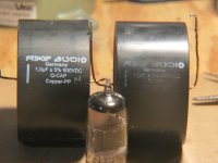
At the urging of a couple of other DIY members that claimed the 12B4 would stomp the Rosenblit Grounded Grid I decided to persur building one.... I left a trail of metal shavings fomr Cody to Rock Springs Wyoming as I partially assembled this on my last service trip. This IS alot more fon that watching cable TV on the motel rooms!

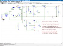
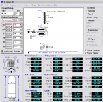
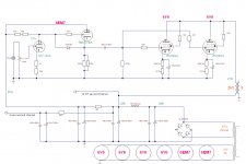
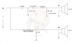
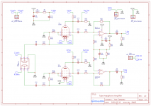
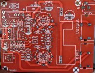
My grounded grid follows this basic diagram. I can't remember where I found this one but it was within a thread on this site that I found the link to it. Mine is pretty much a stock 12B4 as was my Grounded Grid. The only change I made to the grid when I built it was to use a different feedback resistor(less feedback) and a variable regulator IC in place of the fixed 12 volt IC. This allowed me to use the designed 12.6 volts on the filaments of the 12AU7's instead of Bruces 12 volts.

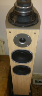
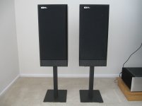
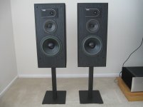
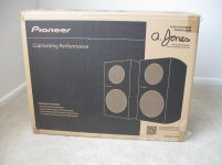
How do they compare.....? Listening tests were done with my Dynaudios driven by my DIY overbiased/overbuilt Aleph 2s. Source was from my Pioneer DV-45 CD player, a long time favorite of mine and one which has the proper DACs for the proper type of disks! All three types of CD's were used in listening tests.

The Grounded Grid is very detailed and open and extremely neutral and very dynamic. Overall its a very pleasing line stage to listen to once a good tube type is found. Yes, its somewhat tube fussy as I finally ended up settling on NOS Tung- Sols in mine. This seemed to be the best choice forthis line stage. JAN tubes while less microphonic were much more strident sounding on the high end. Did I say microphonic....... Yes. The grid suffers from this plague to some extent although I never found it to be a real problem. My stereo rack pretty is well isolated and on spikes.

Overall the grid has been very good and I've lived with it now for well over a year.

Then commeth the 12B4!

What can I say when something is so dramatically better. To try to sum it up I'll say that this simple circuit is the real meaning of more for less. By that I mean more music for less parts used. Somewhat the same basis for the Aleph series of power amps too.

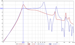
This line stage has detail and top end that have to be heard to be believed and seemingly unlimited dynamic range. Its also drop dead neutral. As a comparison to the GG the 12B4 has alot more leading edge comming through than the Grid does and thats the single most obvious difference between the two. The bottom end and midrange performance are very simmilar to the grid but again with the 12B4 revealing even more detail and nuances deep in the music. This is very evedent on plucked bass and vibes and is pretty amazing. Background noises in recordings start to get annoying with the 12B4! Overall this is a much more musical line stage than the grid. Its hard to believe that high end tube equipment manufactirers have not hit on this tube, their engineers must be :dead: .

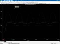
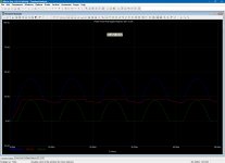
Are there any drawbacks? YES! This line stage has just about zero Power Supply Rejection and requires the very cleanest power you can give to it. Does it need to have a CSS or LED's to sound good. NO! This stock circuit is simply amazing running off my regulated bench supplys. The CCS mod might raise the PSR a good bit but good regulated supplies as Dr. Gizmo used to do and as I am doing also works very well. Its either going to take alot of iron or some well designed regulated power supply to get this unit hum free.

So have I retired my GG? No, it'll serve in another system in another room. Its also a very good piece but the 12B4 does indeed blow right past it.

Simply put the Grounded Grid runs at Warp 5 and the 12B4 runs at warp 9.

Build your self one!

Mark

Attachments

  • 12b4 line stage 011 copy.jpg
    12b4 line stage 011 copy.jpg
    89.6 KB · Views: 18,828

Why are my mids muddy???

Hey guys I'm having a very frustrating time putting together a set of speakers I'm working on. It's a bookshelf, Dayton BR1 bookshelf enclosures with Peerless drivers.

Tymphany 830874 6-1/2" PPB Cone HDS Woofer
Tymphany XT25TG30-04 1" Dual Ring Radiator Tweeter.

I'm running active, crossing over everywhere from 1500hz up to 5000, right now I have the mids just running full range.

Speakers are being powered by a zoudio 4 channel amp with dsp. 50wrms x4 @4oms.

I think one hurdle I'm facing is that my woofers are 8ohms, tweeters are 4ohms.

but whatever I do The sound is very muddy and removed. Question: Should my midwoofers sound GOOD just hooked up and running full range??? they sound terrible... What could I be doing wrong??

I wonder if my amp is just junk ??? not enough power?

Crossover Thoughts

In another post I asked if anyone had built the M J King Satori MTM.
But it seems no one has done so I have some other questions.
1. There are no dimensions for the driver centres but am I right in assuming that with an MTM it is best to get the centre's as close as possible together.
2. I know Martin is well known and well regarded but what do you experts think of the crossover that has been designed for this MTM
Thank you

Options for my latest pet-project.

I have recently acquired a pair of Eltax floor-standing 10i speakers. They are surplus to my requirements and pretty damn awful.

They are literally a waste of space. The twin 5" bass drivers produce little or no bass. However, the design of the cabinet provides room for me to install a 6.5" down-firing sub. (The speakers are on spikes anyway).

The logical solution would be to seal the sub in the lower half of the box. However, this would require carpentry skills beyond my pay grade.

What are the effects of the subwoofer, the two bass drivers, and the port all sharing the same internal airspace.

Hopefully you can see from the pic what I'm trying to do.

Attachments

  • eltax + sub.jpg
    eltax + sub.jpg
    159.7 KB · Views: 176

Shout out to Draloric (Vishay)

I have built a number of Naim NAP250 clones with 20Ω Draloric AC wirewound resistors in their Zobel networks (as in the originals, I believe).

But I've recently understood that their inductance can swamp their resistance at high frequencies, and if said high frequency is less than the fT of the output stage then you've essentially got no Zobel network for half of each cycle.

So I thought I'd better find out what the inductance of my wirewounds is. Of course the datasheet doesn't spec it. 🙁

Being that I'm in no great hurry I fired off an email to Draloric/Vishay. This was around 11pm on a Sunday.

I get a reply at 5am Monday morning: 0.26µH. Now that's customer service!

(And for those of you curious my resistors turn inductive at a bit over 12MHz. Probably another reason NAP250's had a tendency to fail with no load hooked up.)

Help assessing scope readings on an ACA

A friend recently sent me his pair of ACAs to try out. So far I've only messed with tubes, so it proves to be an interesting comparison. I just recently also got my first scope and signal generator, so as part of my learning to use those I went ahead and hooked up the ACAs and tried taking some basic power output and square wave readings.

Things look seriously amiss, but it's likely I'm making a mistake in my test setup so I wanted to get a reality check.

The ACA is running in stereo mode into 8Ω dummy loads, fed with a 1kHz signal from a Tag-101 type signal generator and the compensated 1x probe connected across the dummy load. Scope is a Tektronics 2445. These readings are in DC coupled mode:

IMG_2039.JPG


Slightly up in amplitude from that I start getting distortion of the wave form:

IMG_2040.JPG


So the first image indicates .42Vpp, or .148v RMS. Square that and divide by 8Ω load to get the power output...we're at a tiny fraction of a watt.

I must be missing something, as the amps sound quite good.

Turning the amplitude down even further the square wave looks like this:

IMG_2041.JPG


Any thoughts about how to explain what I'm seeing?

Sub driver as Mechanical Position Servo - Strength?

It's a bizarre idea.

I'm wondering how much weight a speaker cone facing up could lift and hold steady in a position along its xmax? Is there a way to figure this out - ballpark - without actually purchasing a driver and doing an empirical test?

Some car audio sub drivers have incredible claimed power handling ratings. (While I'm sure this is for reciprocating motion and would be significantly downgraded in a static condition - that's a noted detail) Let's say I have a $50, 6" unit with dual 2 ohm VCs; I put 12V DC across each for a total VC dissipation of 144 Watts. Specs says certified @ 250 continuous RMS, VC temperature up to 180C, 4 layer copper VC, etc.

For how long would it hold a static force before exuding "that burning smell"? If I pulled cooling air into the VC gap through the pole piece vent (like the big mechanical shaker tables do)?

I'm mostly interested in figuring the force in lbs that a VC motor can push/pull, from ordinary audio params, such as db SPL / Watt. If its even possible to do so.

If not, guess I'll just have to buy it and see for myself, but I thought I'd ask first. Maybe worth considering just for the thought exercise 😀

Thanks,

Modern sources for TL/ML TL/Voigt designs?

Hello -

Back in 2000 I built a set of Voigt pipes from plans I found on the 'net. They sound great but now that I have a better shop I want to play with other single-driver designs, especially mass loaded transmission lines. I now own a set of Tang Band W8-1772s but have no cabinet to put them in.

Thing is, design information about these has disappeared! Martin J King has disabled his MathCad, Bob Brines has gone silent, and the websites I used 20 years ago are long gone. Everything I can find seems to be from sketchy sources from the back alleys of the the internet.

I'm a woodworker, not an engineer... where can I find a good set of science-based plans than match my drivers?

Thanks for your assistance,
Jason

RF Prime 1200.1D/IRS2092S

Good day all,

I have a pair of Prime 1200.1D’s in for repair, the first one here had a blown power supply and 2 of 6 outputs shorted. Removed all the bad FETs and checked PS drive, looked good despite the burned look of the PNP drivers, but when loaded it was obvious the drivers were bad. Sloppy looking falling edge on the drive wave, so the PNP’s got replaced and it now builds good rail voltage.

The output section doesn’t seem to be doing anything, and I have a blue power LED with red flashing along with it (bicolor LED). This uses the IRS2092S self oscillating output IC, and this is my first experience with it. My question is: will the IC create drive for the output section right away, or does it need a kick to get it going? I tried feeding it an input signal, no change.

It’s possible the chip was damaged by the shorted outputs, but is there a way to confirm it’s bad before replacing it?

What to do with IRF630...have some idea to help me?

O good friend mailed to me many IRF630, he made me a gift, and also he sent me many headphone amplifier schematics that can use those parts.

I really do not like to include stages between CD player and power amplifier, i think each stage distorts something.....so, pre amplifiers is something that i use as weigth to pappers to avoid them to fly away during windy days.

Reason why i am asking you some idea to use them..... as power amplifiers, driving normal speakers.....can be 1 watt, 2 watts or several watts, can be class A or class AB...do not matter to me, what matter is to put them to work, as my friend sent me those units more than 100 days ago and i did not make anything with them.

The friend is someone precious to me...oh!...every friend is precious to us..... and i do not want to pay him with that small respect i am giving him...i want to produce something.


Yes folks...respect is not the adequated word, i do not know what world will fit....consideracao....hummmmm....do not know.

regards,

Carlos

6J1\EF95 Hybrid Tube Preamp, Headphone Amp Teardown and Schematic

Hi,

I'd like to start of by saying the lockdown was driving me insane, so I decided to start my old hobby of breaking and making small electronic circuits. I've not done this for a while.

I love buying cheap stuff hoping it works, I purchased a Fosi Audio T20 Tube Amp and was impressed with it. See profile website for video review.

So I decided to buy a cheap Chinese "Tube Amp", take it apart, draw a schematic, design a new PCB and make it again, hopefully slightly better.
The amp is from AliExpress, and it was £18. It came assembled and was supplied with 6J1 tubes. The headphone amplification is done via NE5532P, the tubes are supplied with 100vdc via a DC-DC booster and the input supply is 12vdc.

DIY 6J1 2 Tube Headphone Amplifier Kit Preamp Tube Board Preamplifier Post amplifier with 3.5MM Headphone / Preamp Output 12V DC|Headphone Amplifier| - AliExpress

To me it sounded fine, I did not notice any overheating\distortion\hum at normal volume levels (did not go all the way up, I value my hearing). it also worked with other EF95 tubes like M8100.

So I desoldered it and drew up a schematic, please note it is the first pass of my board analysis so there maybe a mistake or two.
I love the simplicity of the design, however the pcb tracks were very poorly done, there were vias on the postive rail when it was completely unnecessary, the ground tracks were in a star format, and the soldering was poor.

As I don't know much about tube amps and op amps, I started reading and watching Youtube videos and noted the following based on my limited knowledge and understanding:

  • First thing I noticed was that OpAmps are designed for Positive and Negative supplies, but can be made to work with a normal DC supply by offsetting voltages (excuse my terminology).
  • I also noted some of the coupling caps seem too high, input ones are 1uf and the output is at 220uf.
  • The tube cathode resistor R14 and R19 seem to be missing a capacitor, I know this is optional but won't know what will happen unless I try the circuit with the capacitors in place.
  • I don't understand the point of R1 and D1, the power supply is 12v and the two tube heaters in series should be fine with 12v.
  • I tried to work out if the tubes were biased properly (R15, R14 - R20, R19), but the maths confused me in the end.
  • The potentiometer value seems low, most amps schematics I've seen seem to commonly use 100K.
  • If the DC-DC booster is supplying 100v, surely R15 and R20 is causing a voltage drop meaning the plate is getting less than the recommended voltage as per tube specs that I've looked up.
That's it, I was wondering if people think I'm wasting my time with this (bear in mind I like making things and I'm very bored). Or I should go ahead and maybe some suggestions on design improvement.

Please don't say this is not a tube amp, go and make a proper tube amp with 400vdc and no semiconductors 🙂

Pictures and schematic below.

BTW I searched the forum and could not find anything on this board, sorry if something similar has been posted already.

Thanks


Attachments

  • Schematic_EF95 Tube Preamp - Original_2020-06-04_23-02-53.png
    Schematic_EF95 Tube Preamp - Original_2020-06-04_23-02-53.png
    101.8 KB · Views: 8,086
  • 01.jpg
    01.jpg
    260.3 KB · Views: 3,195
  • 02.jpg
    02.jpg
    271.9 KB · Views: 1,949
  • 03.jpg
    03.jpg
    253.4 KB · Views: 1,598
  • 04.jpg
    04.jpg
    249.8 KB · Views: 3,407

FS: TOKIN THF-51S NOS Matched Pairs

SOLD TOKIN THF-51S NOS Matched Pairs (2 pairs available)
SOLD
SOLD

New Old Stock, Never Used
I bought these from pras1170 in June, out the last few pairs of new THF-51S that pras had available. Projects and times have changed, so selling at lower than cost to acquire. Pairs only!

pras1170 has an excellent track record of properly matching these per Zen Mod's 'Sissy SIT' requirements and other SIT builds. See posts : SissySIT


Ugs measured (heatsink mounted), with 24V for Uds , 2A for Iq for these are:
3.60v, 3.60v, 3.60v and 2.56v
Mounting hardware, isolators and Kerafol Keratherm Red included.
$185. per pair, Free Insured Shipping (US 48states only), I will eat Paypal fee.


First 2 pics are from my initial purchase, the last 5 pics taken today.

Thanks, Charles

Attachments

  • PRAStokin1.jpg
    PRAStokin1.jpg
    67.5 KB · Views: 235
  • PRAStokin2.jpg
    PRAStokin2.jpg
    748 KB · Views: 252
  • TOKIN1.jpg
    TOKIN1.jpg
    430.7 KB · Views: 226
  • TOKIN2.jpg
    TOKIN2.jpg
    525.8 KB · Views: 235
  • TOKIN3.jpg
    TOKIN3.jpg
    529.8 KB · Views: 224
  • TOKIN4.jpg
    TOKIN4.jpg
    652.2 KB · Views: 92
  • TOKIN5.jpg
    TOKIN5.jpg
    705.7 KB · Views: 95

New DIY speaker hunt.

Greetings

So I've been on the hunt for a new speaker. But I have limitations this time as the wife for the first time in our marriage is stepping in... Maybe because the closet full of drivers, xo parts and speakers going to waste.

I can do a new build to last the next few years, but I was given a condition. They have to be a kit or a proven/well designed plan.

Yes there are a LOT of kits, but I've one found two that come close to what I want. One the designer said XO not very refined so he wouldn't recommend it. The other uses a 12" and I need a 6.5-8".

I'm looking for a lot or design using a CD/WG or Horn with a Mid-Bass woofer and NOT a PA woofer. I want something that WON'T have to be crossed at 80+. Hell that's all klipsch builds but their stuff is garbage and costs way way to much.

Does anyone know of a design? And yes I know about Econowave- they use PA woofers, the midbass woofer they use for one is to big.

These will go in a 15x13 room close to corners, budget $160 per speaker for XO and drivers. I am NOT interested in DIYSG, I don't want to sacrifice bass for spl. I'd rather have a 88/89db speaker and have extension. I don't have DATS so I can't measure my self the ZMA and TS, I do have UMIK-1 and HOLM and REW. That's why I prefer a kit/design already unless there's some form of collaboration here. I've heard a few horns and I love the way the sound and make our music more enjoyable, and they look awesome.

phono preamp need more gain

I have a Mapletree Ultra 4A phono preamp that just doesn't give me enough output. The question is can I modify the linestage section for more gain or replace it with something else? Possibly just use the phono portion with a different linestage that has more gain? I'd consider dumping the whole thing but I like the sound of it and the fact that I have a dozen 12SC7 tubes and a box of 50) 1634 tubes.

Presenting my custom built amp (LM3886)

Hey everyone,
I finally finished the documentation of my amp build and wanted to share it with you for inspiration and to give some information back to the community.

All the information including a part list, some info on how I built it, schematic and even 3D models can be found here:

100W HiFi Stereo amplifier with custom case based on LM3886 – Baschteler of Science Blog

stereoamp_finished.jpg


I hope this is useful to some of you and may even inspire new ideas 🙂

Ground isolation method

Hi everyone

I was working on my class D car amplifier and finally I finished it today but when I install the amp in my car as soon as I connect the car stereo ground to the amplifier input, there is a magor current drawing from battery

I use this DC to DC convertor for my amplifier:
800W DC-DC Power Supply

and this is the class D amplifier that I used:
class-d-amplifier-circuit-900W.jpg

900W Class-D Next Generation Power Amplifier - Class D Amplifier Circuit

If I connect my amplifier input to another external audio device like Mp3 player, there would be no problem and everything is okey

How could I isolate my amplifier from car stereo?(grounding problem)
every helf would be appriciated🙂

Speaker Measurement Hardward Recs for Linux

Hi, all,

SHORT VERSION: Someone please tell me what hardware to buy to use Vituix CAD (and other FOSS speaker measurement stuff) under Linux. I mean, really. I don't need links. I can do the googling. But just tell me what to buy, please! Cost is not a major issue but isn't irrelevant.

LONG VERSION: I'm just getting into building speakers but am already feeling pretty serious about it. I've done a fair bit of building of preamps, headphone amps, etc. I'm a pretty good woodworker. too, so it's been fun to merge these two projects. So I'm getting to a point I may want to build some very nice speakers.

Project One was the SEAS-CURV monitors from Troels Gravesen. They aren't quite done but look gorgeous. (Cherry veneer over MDF. Pix to follow.)

Project Two may well be the Ulawatu speakers from Curt Campbell. My wife is learning to play percussion, so these could work really well in her practice system. (I.e., they play loud.) Looking at the measured response, though, it looks to me like I may want to measure the response and tweak the crossover. (Bad hump 100-200Hz that might warrant a notch filter.) But I might build something else.

Whatever! Unless I'm just going to continue building kits blindly, I need measurement stuff. I'm a FOSS person---Linux user since 2000 or so---and Vituix CAD looks like a good option from that point of view. But I'm finding it hard to tell what hardware to buy: mics, sound cards, etc. So help?? Cost is not a major issue but isn't irrelevant.

Thanks,
Riki

Pair of Eminence N314X-8 and H14EA for sale

SOLD Pair of Eminence N314X-8 and H14EA for sale

SOLD SOLD SOLD


I have a pair of Eminence N314X-8 drivers with aluminum Eminence Horns that I purchased for a pro sound project that did not get used. This is the second pair of N314x-8 drivers. I am using a pair for my living room hifi.
$500 for horns and drivers delivered to CONUS.
These horns/drivers were not mounted in a cabinet and only used for measurements.
PayPal is fine btw.

Attachments

  • 636F3E61-A60D-410F-81F5-965F6099D537.jpg
    636F3E61-A60D-410F-81F5-965F6099D537.jpg
    988.3 KB · Views: 270
  • 778D0584-9898-440E-8B8D-9BDD4B8105CB.jpg
    778D0584-9898-440E-8B8D-9BDD4B8105CB.jpg
    876.2 KB · Views: 358
  • 13F186B3-D7D8-438B-B3DC-A7B7728E49C5.jpg
    13F186B3-D7D8-438B-B3DC-A7B7728E49C5.jpg
    589.7 KB · Views: 258

Not a DIY project but some help would be appreciated

I have a pair of Polk M7 speakers. one of the 6 1/2" mid bases is starting to distort sounding scratchy. The only way to eliminate it for a short while is to slightly tap on the speaker near the center but off the dome. It seems to work for a while. When it completely goes I do not want to give them up for scrap.

Does anyone have a suggestion for a replacement driver?

Everything anyone has said about these speakers is true, great depth , clarity of sound, you can listen to music for hours with these and not tire.

Thanks, to all who are fans of these. I know there will be detractors.

Q: "Gold-plated" tube sockets from Aliexpress

Hi !

Is there any reason to buy so called gold-plated tube sockets (for extra cost)?
This gold-colored coating is few microns thin, and probably won't survive even single insertion.

From my past experience gold-plated RCA connectors were gimmicks, coating worn out very quickly.

Silver colored sockets are probably tin-plated.

Thanks for any suggestion(s).

For sale: Sound Dynamics 300TI, Pioneer SP-BS41-LR

Pair of Sound Dynamics 300TI speakers for sale combined with a pair of Target brand stands for $500. The speakers and stands were purchased brand new from Audio Advisor and used in my main system until 2012, when they were replaced by the BassZillas.
The 300TI speakers are in perfect working order and in very good cosmetic condition, as can be seen in the pictures. The Target stands were recommended by Audio Advisor as having the proper height for the 300TI. Their vertical support is hollow and I filled them with shot purchased from a nearby gun store. I will only sell the speakers and stands together to a buyer who will pick them up in Orange County, California. The buyer will be given the opportunity to audition them.

attachment.php


attachment.php


attachment.php


attachment.php


attachment.php


attachment.php


Pair of UNUSED Pioneer SP-BS41-LR in their original box for $150. The speakers were purchased from Newegg.com and, upon delivery, the box was opened for inspection and a brief test. Since then the speakers have been stored in a closet and I don’t think I’ll have use for them.
I prefer to sell them to a buyer who will pick them up in Orange County, California. In that case the buyer will be given the opportunity to audition them. I am willing to ship them in their original box, as they arrived, provided the buyer pays the full cost of the shipment with insurance.

attachment.php


attachment.php


attachment.php


attachment.php

Attachments

  • 300ti_front.jpg
    300ti_front.jpg
    183.7 KB · Views: 732
  • 300ti_removed.jpg
    300ti_removed.jpg
    218.1 KB · Views: 945
  • 300ti_back.jpg
    300ti_back.jpg
    479.4 KB · Views: 903
  • stand_full_view.jpg
    stand_full_view.jpg
    270.2 KB · Views: 658
  • stand_base_plate.jpg
    stand_base_plate.jpg
    337.9 KB · Views: 639
  • stand_stem_closeup.jpg
    stand_stem_closeup.jpg
    346 KB · Views: 640
  • pioneer_boxed.jpg
    pioneer_boxed.jpg
    304.9 KB · Views: 616
  • pioneer_front.jpg
    pioneer_front.jpg
    280.5 KB · Views: 623
  • pioneer_back.jpg
    pioneer_back.jpg
    286.4 KB · Views: 629
  • pioneer_front_back.jpg
    pioneer_front_back.jpg
    295.3 KB · Views: 667

Shunt regulator output capacitor

I have a china/ebay 5V linear power supply that I am re-capping. It looks like a shunt regulator circuit. The smaller 100uf/470uf appear to be helper capacitors for the pre-driver circuit. I can see four zener diodes in each power supply (it's a dual power supply board).

The DC voltage is generated by two IRFZ24N N-Channel MOSFETS wired in parallel. The output pins connect to 0.43 ohm resistors (white blocks in picture), which then both connect to +VOUT. Honestly, this almost looks like an amplifier board (which it is in a way).

However, there is a really big 6000uf capacitor as the output capacitor directly on the VOUT leg (as pointed out in the picture below - sorry for the bad quality). When I removed this, the board is marked for a 4700uf. This seems to me like an abnormally large value to use for a regulator output capacitor. I have a 2700uf Nichicon PM on order for this position (I love PM caps in digital power supplies), but now I'm thinking that I should really put a small cap here, such as a 330uf. I have been told that a really large output capacitor on a regulator could slow the regulator down in some situations.

Does anyone have any thoughts on this decision? This will be powering a digital S/PDIF output board.

Ack, it looks like diyaudio is no longer supporting hosting of inserted pictures, and I don't have a website where I can place this, so you'll have to just look at the original ebay pictures:

HIFI-Linear-power-supply-two-Way-LPS-50W-50W-DC-5V
Projects by fanatics, for fanatics
Get answers and advice for everyone wanting to learn the art of audio.
Join the Community
507,753
Members
7,886,666
Messages

Filter

Forum Statistics

Threads
406,157
Messages
7,886,666
Members
507,753
Latest member
ayodej