Starting a Darling on the bench

I've been wanting to do a Darling Amp for the longest time as I have several Military 1626 and 8532/6J4 tubes and all the parts needed. What I don't like about all the Darlings I've seen is that the left/right tubes all share the same cathode resistor and bypass. I have downloaded at least 50 different Darling versions, and I like the attached one best as a start due to its simplicity. I see some problems though...

1 No grid stoppers, so ill add those as carbon composition
2 Shared cathode resistors, so ill separate those and double the values
3 No leak resistor after the volume control, ill add maybe a 500k there just to be safe.
4 And my big pet peeve is when people don't mark the expected final B+ voltage right on the schematic. So ill put this PS into the Duncan PSD program to see what voltage it would be using these parts.
5 The reservoir cap (first cap) should probably be grounded first at the CT then bring a wire over to the next cap to keep the first loop smaller?
6 Ill set the filament voltage by experiment by selecting the best dropping resistor in a closed loop to hit 12.6 while hot.

Any other items on this I should look out for? Any Darling veteran advice?

se1626-1-bill1.gif

Dynaco ST-150 and new oscilloscope

After 50 years getting my feet wet. I bought a Dynaco ST-150 and have a 9db difference between channels on output. I have reset the bias and dc offset and they’re right on. My question is really about the oscilloscope and the design of this amp. The negative speaker terminals are grounded to the chassis(2 wire cord). When I read the chassis/negative speaker terminal to the ground on my oscilloscope lead, I get 20 M ohms. Am I safe using this probe on the output terminals of this amp given its design? My apologies in advance if this belongs in equipment but I wanted to reference the design of this particular amp in the question.

10 year old bug in software.

Many years ago I wrote a PCBCAD software package.

The printer output was done using usual draw line, draw ellipse etc commands.

I found for some reason the text was a bit distorted but had never been able to find out why.

Yesterday someone asked me to add sheets (A1 - A6) on the schematic.
So I added this in and again wasnt terribly happy with the print output.

I found the output was being reduced in width by a factor of 10 somewhere in Microsoft kernel.

So I dug into the internet to see if I had missed something and probably spent a day on it.

I eventually spotted a command e.Graphics.ScaleTransform(100f / 1000, 100f / 1000);
This scales the graphic resolution of 1000 pixels per inch into 100 pixels per inch but doesnt lose detail.
This works better by a factor of 10.

So the problem has been there for 10+ years. Strangely no one who bought the software complained about the text.

Best SS Diy Phono Preamp

I recently came across an article by Marshall Leach " Construct a Wide Bandwidth Preamplifier" The article mentions Daniel Meyer as a reference and the schematic is similar if memory is correct to the phono preamp that Meyer put out as a kit in the mid 75-77 era with the exception that Leach used Fets in the front end of his phono preamp instead of discrete transistors. Meyer actually had two versions of the phono preamp board with the later sounding better. Sorry, all my Southwest Tech info was lost in a recent move so I cannot mention specific board numbers or model numbers. I can only remember the phono board sounded very good if my memory is still intact.

To make a long story short I have the article in hand which includes the circuit board foil pattern for the RIAA input board along with the output board. I don't know how to make a board so I am either seeking information on a company that would make a board or a newer circuit that will sound good, have discrete transistors instead of OPAMPS and the ability to purchase a blank circuit board.

Any help or ideas would be welcome. I would like to keep this as a project since I am retired and bored out of my mind needing something to put together. I would like to mention I am a Tube Freak and currently have a tube phono preamp but would like to give this a try.

"YEDS-3" CD

Hello all :wave:

I'm doing some adjustments on an OLD :geezer: CD player of mine.
in the service manual, it clearly states, that a Test Disc YEDS-3 is required.
I've searched high and low on the web without any luck 🙁
All and any help would be very much appreciated 🙂

Cheers and stay safe.

PS🙁by the way, it's an old pioneer p-d1 from 1982 I believe).

Correct wiring of transformer in a passive DI box

Hi everyone,
I'm building a passive DI box with parts that I've acquired throughout the years. I've identified both windings for proper phasing but my question is: What is the best way to send signal to the transformer for best response? Is it best to insert signal at the begining (the wire end of winding closest to center core of transformer) of coil wind and ground the finishing end of the winding or the other way around? Does it matter?
I always thought that the dots at the winding lead denoted the beginning of the wind but it looks like they are actually there for phasing purposes.
Thanks.

bic venturi formula 4

Goodmornig from Athens,Hellas!
I own from my father a pair of bic venturi formula 4 and i want to upgrade them.
The mids and higs are too match for me ,if they still works and the bass too boomy.
I'm thinking to replace the horns with a tweeter and replace the midrange too.
Also make the cabin closed box.
Which components do you think i should put to them?
Thank you a lot!
(and sorry for my english )

dpa enlightement drive / Philips VAM 1202/12

Hi,

I have to make a CD-Transporter work again, and unfortunately i´m struggling.

Its a dpa "enlightement drive", based on a Philips VAM 1202/12 Pickup/Drive.

The issue is, when a CD is about to load, the lense is moving up and down 3 times, but it wont read (Error).
I already replaced the pickup with a new one, and sometimes it works, CD gets recognised and read.

it seems to help to give the upper clamp (which is magnetic) a little push with the finger (not a spin, just a push) while its trying to read-out, then it starts sometimes

Maybe its a problem with the clamp? lost magnetisation over the years? i put an extra little neodym disc magnet on it, didnt help.

The drive is rubber-mounted, as you can see in the picture.

Do you have any ideas?

thank you, Daniel

Attachments

  • IMG_20210129_194720.jpg
    IMG_20210129_194720.jpg
    694.6 KB · Views: 143
  • IMG_20210129_194809.jpg
    IMG_20210129_194809.jpg
    541.9 KB · Views: 124
  • IMG_20210129_194747.jpg
    IMG_20210129_194747.jpg
    621.8 KB · Views: 136
  • IMG_20210129_194739.jpg
    IMG_20210129_194739.jpg
    602.3 KB · Views: 123

Analog Servo Sub

After talking about my servo sub project in another thread (http://www.diyaudio.com/forums/subw...-gain-servo-controlled-woofer-controller.html ) I decided to start my own. Mostly because I don’t want to clutter his thread with my project, but also so I can present my system and my results in one place. Hopefully this will make it easier for you to give me feedback on what I have done, what I have done wrong and what I can do to improve the system. Please don’t hesitate to be critical. I don’t know much about feedback systems and while it seems I have had some success with the things I have done so far I am sure there are things I should change.
This project started 5 years ago(!) following an article I read in audioXpress 6/06 by Art and Jac Brown. It was put on the shelf until recently when I was inspired by David’s DSP servo efforts in the thread above. Later I have also acquired an article written by Bill Waslo in audioXpress 12/06. He manages to explain how to build and test a servo sub without going into difficult math. The latter suits me particularly well 🙂

System setup:
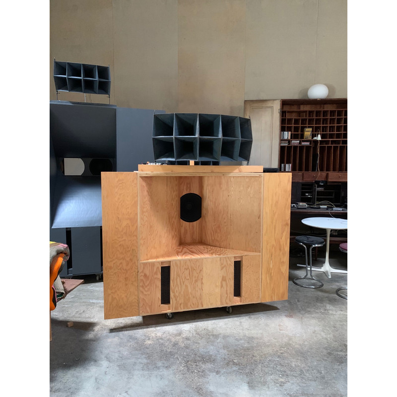
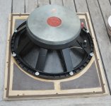
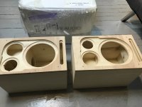
Woofer: PEERLESS XXLS 12” (830845) in a 135 liter (4.77ft³) sealed box.
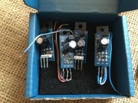
Accelerometer: ACH-01-03. Calibrated to 9.6mV/g @ 1kHz
Amplifier: DC coupled LM3886 with +-29V rails
Sound card: M-Audio Audiophile
Pre-filter: MiniDSP 2x8
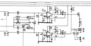
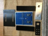
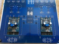
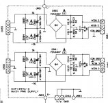
Servo circuit: My own. See schematic.

Measurement tools:
Oscilloscope: Picoscope 3224 (12-bit)
Multimeter: Fluke87
Measurement mic: My own with Linkwitz mod. (calibrated)
Software: REW V5,01 Beta 17

Modelling software:
Speaker: Unibox 408
Electronics: Proteus


Figure1.png
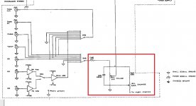
Figure 1. The servo circuit with a graph simulating the response from the accelerometer input to the amplifier output.

Figure 2.png
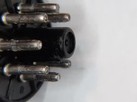
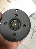
Figure 2. The accelerometer mounting. It is glued with 2-component epoxy under the dust cap. Note the 4gram counterweight on the opposite side.
Figure 3.png
Figure 3. The accelerometer cable comes out between the voice coil wires

The servo circuit.
This is mainly built following Brown’s suggestions.

Input buffer (U1)
A 7400Hz LP filter takes away some of the high frequency noise from the “MiniDSP 2x8” I use as pre-filter and EQ. U1 also serves as input gain adjustment and DC-offset adjustment. The MAX427 has low drift and noise and is unity gain stable.

Accelerometer input (U2)
R6 is needed for negative bias of the accelerometer. C2 and R7 form a 2.1Hz HP filter and prevent the slow DC changes that occur in the accelerometer from entering the servo. R9 and R8 give a gain of 9.4. The accelerometers sensitivity of 9.6mV/g will then be amplified to 90,24mV/g. The op-amp’s rail voltage is +-15V and the OPA637 can swing to about +-13V. Maximum g-force before clipping is then 13V/(90.24mV/g)= 144g. The OPA637 is probably overkill but it was in by box and it’s nice to be on the safe side

Summing amp (U3:A)
The accelerometer signal and the music signal is summed at the positive input of this op-amp. Note that the accelerometer is mounted so that an outwards (positive) motion of the woofer gives a negative signal here. This op-amp also serves as loop gain adjustment with R5 and LOOPGAIN1. I can have up to 32dB gain here. It is now at 29dB.

LP filter and output amp (U3:B)
R10 and C3 form a 4.3Hz LP filter. It attenuates high frequencies and helps shape the phase response so that the accelerometer feedback is inverted (180deg) at the target frequency. I wanted the target frequency to be in the lower part of the woofer frequency band because it is there we have most distortion. In my case this is now at 39Hz. This is a critical area of the servo circuit and this filter has to be shaped to suit the particular woofer/box. I have tried a couple of things here but this is what is working best for now. Both articles I have linked to earlier have more information about this. This op-amp also has a loop gain adjustment with R11 and LOOPGAIN2 of up to 25.8dB. With mine set to 18.5dB (pot at 2k) the system starts to oscillate at 2560Hz and increases fast in intensity at 2480Hz. At 17dB (pot at 1.63k)the system is just stable and I measured all-time best of 0.95% THD at 20Hz with 18.5V RMS on the speaker terminals. The last potmeter (AMP_SHUTDOWN) serves as a quick way of turning off and on the output amplifier when doing adjustments or if things goes “tits-up” 😀.

The output amplifier.
After struggling with low frequency oscillations (1-3Hz) with a standard Rotel amplifier I decided to get rid of the extra 90 degree phase shift that occurs in all standard amplifiers that have a DC blocking capacitor on the input. I also wanted an amplifier without too much power that could rip my woofer apart during testing. I have therefore built a DC coupled LM3886 chip amp with adjustable rail voltages from +-16V to +-29V I can use during testing. Without the extra phase shift I got rid of the low frequency oscillations and its capable of 19V RMS output
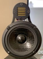
The accelerometer
This is glued with two component epoxy just on top of the voice as showed on the picture. The weight is about 4 grams and a 4 gram Norwegian coin is glued on the opposite side as a counter weight to avoid wrong balance in the cone.
G-force and SPL calculations:
With 100W power at 100Hz the X-Max is estimated to be 1.9mm in my box. The SPL @ 1 m is then 107dB from a 12” woofer. ( SPL = 20*LOG( (1.18/0.00002) * (0.0466m^2*0.0019m/1.41) * (2*3.1416*100Hz^2) ) = 107dB ) The g-force is then 76g ( g = 4*PI^2*100Hz^2*0.0019m/9.81 =76g ) and the “weight” of the accelerometer at that force will be: 4gram * 76g = 304 grams. This would create a bending force that could make the voice coil crash into the magnet.

Testing
First thing to test is open loop response to see what I had to work with. I used REW for this and set it up to sweep from 2Hz to 5kHz in 20 seconds. I made sure that the soundcard and filters included in the signal path was corrected for gain and phase errors with a calibration file. REW has a procedure for this. Here is the results of a loopback with correction active.

Figure 4.png
Figure 4. Measured loopback response with -5dB FS output in REW. Output is from the servo circuit’s input amp with gain set to 0dB. The gain and phase error in the soundcard and servo input amp is corrected with a calibration file so we have 0 gain and -2,9 deg. phase from 2Hz to 20kHz. The black dotted line show the gain correction, and we can see that the 7400Hz input filter has been corrected for. I don’t know why REW insists on correct the phase to -2.9 and not 0 but it is not critical. REW is also calibrated so that -5dB FS output signal is 0dB in the charts. -5dB FS on my soundcard is 989mV RMS. Now that the levels are calibrated and verified I can measure the open loop response.

Step 1.
First I measure the response of only the subwoofer. To get the true phase response of only the woofer I must have a DC coupled amplifier and must omit the HP filter in the accelerometer input and feed the accelerometer directly into the soundcard. Note that this can be somewhat risky because the output of the accelerometer can have a small negative bias and the electrolytic capacitor on the soundcard will have wrong bias. I have addressed this by using a -6V regulator to feed the negative bias of the accelerometer and the output signal from the accelerometer is 0V

Figure 5.png
Figure 5. This is the gain and phase response of the woofer with feedback directly from accelerometer. This plot does not contain any other gain or phase elements other than the DC coupled LM3886, the woofer/box itself and the raw inverted accelerometer output. Top graph is phase. Sweep 12s @ -21 dB FS. I ran this at different levels with the same result. The actual g-force can be calculated by knowing that 0dB on the chart is the same as -5dB FS which is 989mV. From the plot we see that 30Hz is at -31dB. The RMS voltage is then 10^(-31/20)= 28mV. My sensor is calibrated to 9,6mV/g and the RMS g-force is then 31,6/9,6= 2,9g
From this test I was surprised to see that the phase will never cross the forbidden 0 degrees or 360 degrees. In theory it should be possible with infinite loop gain??

Step 2.
Now I want to see how only the HP filter of the accelerometer op-amp affects the loop response. The input to the soundcard is now connected to the output of the accelerometer amplifier. The output from the soundcard is still connected directly to the amplifier (trough the input buffer U1).

Figure 6.png
Figure 6. The blue plot show how the accelerometer filter affects the phase at low frequencies. REW does not let me measure down to DC, but to predict the phase close to DC I have the following theory: We must assume that the woofer itself will approach 180 degree phase shift at DC (remember the accelerometer is inverted) and then the accelerometer capacitor gives us another 90 degrees more phase offset and end up on -90 degrees.

Figure 7.png
Figure 7. This is the SPL from the test. Green is with accelerometer amp. The green graph is actually 20dB higher because of the accelerometer amp, but I have offset it to better see the difference in output.

Step 3.
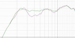
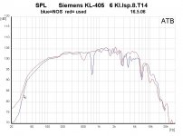
Now it’s time to connect the rest of the servo circuit and see what kind of margins we have. The signal that was driving the amplifier directly earlier is now fed into the summing amplifier (U3:A) through resistor R3. (Just as it will be in normal operation). The input to the soundcard is as in step 2 fed by the accelerometer amplifier (U1). The accelerometer is NOT connected to the summing amp.

Figure 8.png
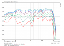
Figure 8. This is the total open loop response. Gain increased until just below oscillation. Sweep done at -40dB FS. That is 35dB lower than the reference level so I have offset the curve +35dB in REW afterwards to easier interpret the plot. The loop gain is +35dB @ 21Hz. From 30 to 50Hz it is +38,5dB and at 100Hz it is +33dB
We can see that the forbidden phase of 360 degrees where the system will oscillate happens when the gain is at 0 which makes sense because the system is now adjusted up to the verge of oscillation. From the plot we can see that this happens at 3640Hz. I don’t know why the (measured) oscillation in my case occurs at 2470Hz and not 3640Hz but it I guess some strange things happen in this area.
But keeping loop gain this high is of course pushing the limits and I adjusted it down 8,5dB.

Figure 9.png
Figure 9. Loop gain adjusted down 8,5 dB.

All testing was done with this loop gain setting. I will post the results in another post

Solid State forum have become a dumpster of commercial cadavers

The attached screenshot pic taken just a moment ago says it all, full of commercial gear in need for service help nothing to do with DIY SS amps but "DIY repair and service".

It's so easy to set up a new forum and doesn't have to wait for anything like the long awaited and delayed upgrade to new forum software XenForo, I would suggest to put the new forum (name suggestion: "Service & Repair") high up, perhaps highest on the list ie above the current Solid State so it's sink hole effect will have a maximum effect sucking in all the quick and lazy "fix my stuff" help request posts that is now swamping Solid State.

Attachments

  • Solid State - diyAudio.jpg
    Solid State - diyAudio.jpg
    135.7 KB · Views: 355

after posting, when posting again the first quoted text remains

I have noticed the following:

I make a comment quoting the text of an existing post as part of my comment. I submit my comment and then go to reply to another post in the same way, quoting the text of a another, different post.
When I do that, the text from the post I quoted in my first comment is still in the dialog box along with the text from the second post I quoted.

Shouldn't quoted text be cleared out once the comment has been posted?

Ht Transformer identification

Good evening,
About 12 years ago I purchased a set or transformers to build a 5 - 10 amplifier.
One is marked up VVT so thats fine can get the data on that no problem, the HT transformer has a label but doesnt state the manufacturer, only the following
DB 1393 15W Mains TX, does anyone on here recognise that data?
I have tried googling but to no avail.
I would like to know what it is just incase i want to make another.

Many thanks

Rich

Kicker ZX1500.1 protects when driven hard

While steadily increasing drive input it works well until it is drawing approx 50 amps on the bench ps and then it goes into protect (prior to output clip).

Although I do not believe I have maxxed out my bench supply, could amp be doing this due to limitations of the supply? Usually an amp just starts to output clip when it maxes out my supply, but not go into protect.

Am about to trace out the overcurrent circuit as I have no drawings.

Any help would be great.

  • Poll Poll
Poll: Which of the three? Aleph J, M2X, F6

Best choice to add to a growing Pass collection

  • Aleph J

    Votes: 42 63.6%
  • M2X

    Votes: 9 13.6%
  • F6

    Votes: 15 22.7%

As someone who has built three F5s I'm trying to figure out which one to go for next. After scouring through pages of Aleph J and M2 posts it seems there is still not only a division but some overlap between people calling the Aleph more rounded, soft and tube like and then similar statements against the M2. Or equally divided as to which one is "better".

I enjoy the articulation and detail of the F5 and was considering an EL84 or 34 tube amp for the second system just to get back into the tube scene. I am not after a lush romantic sound but something that is different enough to have as a complement to the F5 in an amp rotation and provides maybe a little more magic in the mids and highs rather than F5 matter of fact presentation.

Speakers are a monitor designed by my friend with Vifa woofers and scanspeak tweeters. Nominal 8 ohm and only 87dB but they play fine with F5. No issues with trying to tame any frequency as they are transparent and balanced to me. Just a matter of flavour now regards to amp choice.

And both or all three may be built eventually but this is my next project for the spring. Appreciate all the opinions.

12AX7 Style Amber Vacuum Tube LED NIGHT LIGHT Ham Radio TV Guitar Amplifier

12AX7 Style Amber Vacuum Tube LED NIGHT LIGHT Ham Radio TV Guitar Amplifier

Brand: Marshall, Type: Guitar Amplifier, and at the pictures actually show one guitar-amplifier, without words ;-))

someone published it on electronixandmore (webarchive) in 2003, the chinese make everything for money too!

Voltage Regulator Tube Nightlight

Attachments

Focal .JMLab/BASH/Indigo subwoofer problem

Hi, I've noticed there are A LOT of threads on the topic already. I have used the search function but I have some questions in addition to those already asked/discussed, so please bear with me!

The PSU board is Indigo 600109.
q401 and q402 are both broken (IRF740) - this part is readily available. As this seem to be a common problem, why not put in a tougher component? Any suggestions? (I buy components at Farnell if possible. Otherwise ELFA or RS)

Apart from these and a couple capacitors starting to gain a bit of ESR, the board seems to be ok.

The board next to it (with the power amplifier transistors on it) is simply labeled Indigo (c) 2002. Again a few bad capacitors as expected, but here's the puzzle:
One transistor Q100 is labeled 108 C930AB. My first guess is sanyo 2sc930 - but the 2SC930 is ancient and discontinued long ago, and the marking on the casing does not resemble what I find if I google the part. Also according to the datasheet, the gain is marked by C, D, E or F. Nothing on the AB suffix. Pins 1+2 are shorted so the part has to go (unless it's not a transistor at all, and meant to behave this way 😕), so what do I replace it with?

Amplifier hiss with no input signal

I have a beginner question. I am using 3 ClassDAudio SDS-250 amp modules to drive a pair of 3-way active speakers. When there's no signal going into the amps, I can hear a faint hiss coming out of each of the speaker drivers. It's not loud, normally I don't notice it. At night, when everything is quiet and the music stops playing, that's when it becomes obvious. Is this kind of hiss normal, generally speaking, for class D amps? Is there an amp specification that would indicate the level of hiss the amp will produce? Is it possible that the way I have things connected is causing the hiss, or making it worse? Thanks!

Adcom 5800 - Nelson Pass, others

I'm baffled as to why my 5800 is having such a tough time driving my ML CLS2A's(glary mids and tizzy treble). Granted, the CLS impedance dips to less than 1 ohm @18-20kHz but I always thought the beefy power supply and 16 output devices/ch of this beast could handle the job. Can this be remedied by bias adj or some other relatively easy tweak? Appreciate any input?

Jerry

Active load output stage

I found this site:

Link

It shows an active-load amplifier.
It is simply an SRPP output stage.
I never saw an output stage like this one before, so my question is:
Is this one a good solution?
I have 4 KT88, I could realise an amplifer wih this topology, but why nobody has already built it?
My idea was to build an SRPP input stage using two 12AX7 (paralleled) and then drive with it an SRPP output stage made with KT88.
It seems to be a good solution: a perfectly balanced PP output (if you make the right calculation...), more (twice) power than SE, pure class A, more speed and dynamics (at least this is the theory).
Why it is not used at all?
What are your feelings?

Ciao,
Giovanni

Getting lost in research, Need some guidance on what to do with a pair of Alpine 10"s

Getting lost in research, Need some guidance on what to do with a pair of Alpine 10"s

Greetings! First post here. I have been delving deeper into the world of diy audio, and I'm stuck in an area of analysis paralysis and was hoping that you fine folks could help me make some sense of this rabbit hole I have spent too much time in 😀 I'm a total noob, so bear with me.

Here's the situation:
I started construction on these LXC lxmini clones outlined here:

LXC - cdenneler

I'm still waiting on the 3.5" drivers to come in, and I'm using the dayton dsp-408 to dsp instead of the minDSP

I have put together the rest of them though and gave a listen just with the 6" dayton drivers, and I must say just like that they are pretty nice, missing a bit of high end, and a bit of low end though, as yet I have not applied the dsp (waiting on the dongle which is also backordered so I can use my smartphone to control it, since I don't have a windows machine)

I have the extra channels on the dsp, and a pair of 10" alpine SWE-1043 subwoofers laying around so I figured I could add them to the mix to support more of the lower end bass.

I have attached the parameters of the subwoofers

I listen to a lot of more electronic music but pretty dynamic stuff, so I'm more into getting accurate reproduction of the music, in my mind a fast kick should not have added boom from the subs that isn't there in the recording, and long bass sweep should be undistorted and uncolored by the subs as much as possible.

I live in a pretty old house that rattles a lot too so dealing with that is an issue. I like the idea of open baffle not exciting the room modes as much, thus I have been lead down the dipole/ob rabbit hole, and I'm getting very confused. I don't know if these subs will sound ok like that. I have looked at linkwitz lxmini + subs and the lxstudio, I like the look of his m frame subs? but I don't at the moment have 4 subs. while I will probably upgrade to better stuff in the future I don't have the funds at the moment, while suggestions in the upgrade arena are welcome, I'm trying to get the best out of what I currently have right now, so currently that's more the type of advice I'm looking for

I was thinking I would put a crossover somewhere in the 100hz - 150hz range and let the alpines handle everything below that

I have googled a lot at u frames, h frames, slot loaded open baffle, and ripole type configurations.

I like the idea of ripole woofers, they look neat, and from what i understand the slot loading could take my subs down from 29db to 19db. This is exciting. from all the information I have gathered though they are wildly inefficient, and there are some definite haters out there that have likened them unto a "do nothing" machine. I have yet to see any real measurements of them done as to their performance and how inefficient they are so i can figure out what kinda spl they are going to be capable of with the power handling ability of these particular subwoofers.

I'm interested in maybe looking in the direction of putting each sub in it's own h frame or u frame, and sizing the frame about the same size as the recommended sealed box enclosure, that way if I hate it, I can just cover up the backs and use them as sealed boxes. I could also try "slot loading" the back to see what kind of effect this will have on the frequency response.

maybe I'm just crazy to try doing a dipole configuration with these subs and they won't deliver the authoritative bass I'm looking for and I need to just go another direction in general. maybe a throat loaded horn of some kind? I'd like to avoid that if possible, my technological ability to model them is hindered by not having a windows pc, and my woodworking skills might also be lacking enough to tackle that successfully, and I lack the materials to do that in keeping with the "working with what I have laying around at the moment" style I'm currently trying to design for.

Thoughts? Ideas? Tell me I'm dumb and these subs are garbage? Thanks for taking a look!

Attachments

  • Screen Shot 2021-01-27 at 2.46.07 PM.png
    Screen Shot 2021-01-27 at 2.46.07 PM.png
    214.4 KB · Views: 142

Randy's new project with TU-8600S

Hi Victor,
First, I wanted to thank you for the great TU8600s kit. It’s the best amp I’ve ever had!

Do you still have any available? I might eventually want another if that’s possible.


Thanks for your hard work and congratulations on making this your fulltime gig!

Attaching a pic of early Altec H110 A5 cabinets that I recently built.
The 8600s drives the 515bs to thundering bass levels, very happy with the amp/speaker combo.
Randy

randy.jpg
[]

FS: Panasonic 2700uF 200V snap-in lytics

200V 2700uF electrolytics. Stored on my shelf for ca 10years. Never used, and need to be reformed (which do all electrolytics if you care).

Cleaning out my closet... I invested in these ca 10years ago, the plan was OTL amplifiers. Well, havent materialized yet has it... Need to limit my project possibilities since I just go around too many projects hardly finishing any...
How about 40USD for 10pcs?
Shipping from Norway. Not the cheapest.
12 of these go into 1kg, they are ca 80grams each. The price of shipping is divided into kg as follows:
(Exchange rate as of today, 29 Jan 2021)
Shipping to:-------Europe in Euro---------The World in USD
1kg = 12caps = ---312NOK = 30eur--------348NOK = 41USD
2kg = 24caps = ---338NOK = 33eur--------410NOK = 48USD
3kg = 36caps = ---364NOK = 35eur--------472NOK = 55USD
4kg = 48caps = ---390NOK = 38eur--------534NOK = 62USD

So since the shipping starts off with a relatively high minimum of roughly 30euro or (41USD if you are in the older and newer world) it might be 'smart' to buy more than a dozen...
How 'bout:
12caps = 40USD+shipping
24caps = 75USD+shipping
36caps = 100USD+shipping
48caps = 120USD+shipping
?

Attachments

  • 20210129_171634_resized.jpg
    20210129_171634_resized.jpg
    508.9 KB · Views: 95
  • 20210129_171705_resized.jpg
    20210129_171705_resized.jpg
    517.5 KB · Views: 105

HP 8903A software options

Today I purchased a HP 8903a Audio Analyzer from a fellow forum member. I am interested in connecting the analyzer to either my laptop or my PC. My laptop is preferred and it has an i5 2.5GHz processor with 8GB RAM running Win 10 64 bit. I see there is a HP Keysight Agilent 82357B USB-GPIB Interface available for connectivity. Is the Audiotester and Peter Millett software the way to go? This is a new hobby for me where I would like to repair and test vintage audio equipment.

AB amplifier DC instability

Hello, I made a simple amplifier, for learning purpose, with resistive load.
Here the schematic:

Amplifier — ImgBB
This AB amp even without load is unstable, I can't get a stable 0 voltage at the output. Sometimes is few millivolt and is ok, sometimes is at the same level of the positive or negative supply rail (24V), sometimes start from +/- 24V and than slowly goes to 0V and keep this voltage for time and then again unstable.
This happen without input signal, only with DC polarization.
With connected load is totally unstable, never I get 0V at the output, but only negative or positive supply voltage.
When is stable it can amplify an input signal (without load) with good sine waveform, no HF oscillations, but still remains the DC instability, so the amplification doesn't last long.
With Spice is everything good, I have 40mV at the output. The PCB is with SMD components only output transistors are TH with heatsink.
Can you help me to understand why?
I know there are errors but DC point should be stable with this schematic.

Uher CR240 hiss in output stage/general noise reduction

Ahoy,

I'm in the final stages of restoring this having made a new switch and repaired a main board crack and the aftermath of a small fire among many other things.

With the unit on, nothing in circuit except the output ICs, and volume on minimum there is significant hiss in the headphones.

As a transistor neophyte, feeling my way, I wondered if anyone had any suggestions as to where the constant output stage noise is coming from and what I could do to mitigate it in an existing circuit.

Attached is the diagram - the previous IC and all other boards are removed so there is no input. If I ground the input pins of each channel, there is a buzz somewhere between motorboating and mains hum.

I notice the datasheet of the op-amp contains more capacitance on the power line. I think this could be a culprit, as if the motor is engaged (with no connection between the heads and the output) there is hum added to the hiss. While the diagram says C37 is a 1µF/35V, the tantalum capacitor in circuit was 0.1µF (I replaced it with polyester).

There is 4.6VDC on the output, reduced to 3mV after the coupling capacitors.

Attachments

  • CR240_Output_stage.PNG
    CR240_Output_stage.PNG
    234.9 KB · Views: 217
  • TBA820.PNG
    TBA820.PNG
    44.2 KB · Views: 230

why does Rod Elliot say regulating is hard on the MOSFETs

Switchmode Power Supply For Car Audio

Two quotes from Rod's article

"For example, I use a 3:1 transformer that would give about +/-38V without regulation that is unacceptable for my LM3886 stages to be safe, so I have regulated to +/-26V. The MOSFETs will suffer more, however, so regulate the supply only if strictly necessary."

"as stated above, my version is unregulated. This will maintain maximum efficiency, and also reduces the dependence on the output filter capacitors"


Why would regulation using PWM decrease efficiency and but more thermal stress on the MOSFETs? This is not linear regulation after all. Or is it because he does not use output inductors?

Thanks

Kemhet PEGI Electrolytic Series Caps

Hi guys,

I have been looking at the Kemet Pegi electrolytic series of capacitors for a RH84 SE Valve amp project.

Has anyone used these before they seem to have good specs and long life?

The C1 47uF 450v is in the PSU and I could go with that or a Motor Run Capacitor.
PEG124YL2470QL1 | KEMET 47μF Electrolytic Capacitor 450V dc, Through Hole - PEG124YL2470QL1 | RS Components

Capacitance: 47 uF
CapacitanceTolerance: -10/+30%
Voltage DC: 450 VDC
TemperatureRange: -40/+105°C
RatedTemperature: 105°C
Life: 22000 Hrs
Resistance:1200 mOhms (100Hz 20C), 530 mOhms (100kHz 20C)
Ripple Current: 0.377 Amps (100Hz 125C), 2.4 Amps (5kHz 60C), 0.89 Amps (5kHz 125C)
Leakage Current: 63 uA (5min 20°C) 0.377 Amps (100Hz 125C),
Inductance: 17 nH (ESL)

Any thoughts and opinions welcome

Motor Run Polyprop 46UF 450v
https://uk.rs-online.com/web/p/products/9119421/

Thanks

Servo Bias Schematics

Schematics of 4 channel servo bias board for KT88/6550 PP output stages. C7 should be a good quality cap such as film and is 100V. C8 is low voltage 10uF ceramic. POWERUP should be a 0V for 25s or so until the cathode emission starts and then pulled to -10v or greater to make the bias active. R34/R33 sets the bias current in this case 36ma or so. Transistors 100-120V PNP good Hfe.


Enjoy.


20210128_174516.jpg
Screenshot from 2021-01-28 17-55-18.png
Screenshot from 2021-01-28 17-56-06.png
Screenshot from 2021-01-28 18-18-11.png

XEN SLHPA full kit including MB & case

SOLD XEN SLHPA full kit

Fully built kit with Xen Mainboard and enclosure.

Kit includes -
2 x SLHPA modules built and tested with well matched transistors.
1 x Protection board fully built, untested
1 x Danyuk Xfeed with Alps 10K pot built and tested.
4 x Xen Regulators built and tested.
1 x Mainboard - brand new, unused
2 x Talema 70063K 25VA 15V transformers
1 x Case parts for full enclosure plus fixings.

Mainboard comes with a few parts like fuse and components for 15V supplies for front protection board.

Electronics sold, only case remains

Attachments

  • IMG_2420.jpg
    IMG_2420.jpg
    162.3 KB · Views: 227
  • IMG_2425.jpg
    IMG_2425.jpg
    135.7 KB · Views: 237
  • IMG_2421.jpg
    IMG_2421.jpg
    131.5 KB · Views: 231
  • IMG_2422.jpg
    IMG_2422.jpg
    112.9 KB · Views: 229
  • IMG_2423.jpg
    IMG_2423.jpg
    108.3 KB · Views: 225

Help with new mid/bass driver to B&W CDM1 SE

Hello friend ,
I need to replace the woofer on my B&W CDM1 SE speakers
i want to replace them with other new midbass driver
anyone know which drivers is best alternative for this speaker ?
this is the only CDM1 SE information i found :

Power Handling (RMS): 30W - 120W Watts RMS
Frequency Response: -6dB at 46Hz and 30KHz
Sensitivity (dB): 88 dB
Impedance (Ohms): 8 Ohms

165mm KevlarÃr bass/mid. 6-1/2"

thank you

Hybrid H-Frame, OB and nude driver

Gents/Gals,

I am hopping for some recommendations on my first "serious" OB speaker project after playing around with a pair of Hawthorne Audio Silver Iris 15.


The room:

My dedicated audio room is 14' x 17' and acoustically treated; the first reflection points have floor to ceiling absorbers, the front wall (behind the speakers) has 9" deep broadband absorbers with a custom stepped diffuser face, the back wall (behind the listener) has bass traps and a huge custom stepped diffuser that's about H 3' x W 7' centered at ear level.


The equipment:

I have 2x miniDSP2x4 for crossover/EQ duty and for amplification a "couple" of Rotel power amplifiers at my disposal (i.e. RB-1090, RB-1080 and RB-985 Mk2). I am also looking at used Crown or QSC pro amps for the LF section if my RB-1090 isn't enough.


My wants:

After months of reading (e.g. diyAudio, Linkkwitz, MJK, Audiokarma, etc.) I am pretty certain of I want:

- As much as possible constant directivity across the full range;
- 91+ efficiency; and
- Either a 4-way multi-driver or a 3-way using an 8" full range:


4-way:

- For the LF (30 to 200 Hz): I am planning on using Fane 15-400LF in a H-frame, but I am uncertain of the dimensions;

- For the lower mids (200 to 800 Hz): I would like to use 12" woofer (I need recommendations) in a flat baffle that is isolated from the H-frame (i.e. Sorbothane hemispheres);

- For the upper mids (800 - 2500 Hz): I am planning on using a nude Peerless 830875 suspended by cables;

- For the highs (2500 Hz+): nude back to back RT-4001 ribbons, or GR Neo 3 or Aurum Cantus AST2560 suspended by cables.


3-way:

- For the LF (30 to 200 Hz): I am planning on using Fane 15-400LF in a H-frame, but I am uncertain of the dimensions;

- For the mids (200 to 2500 Hz): I would like to use a nude Tang Band W8-2145 suspended by cables;

- For the highs (2500 Hz+): nude back to back RT-4001 ribbons or GR Neo 3 or Aurum Cantus AST2560 suspended by cables.


Questions:

1. Is one Fane 15-400LF pro woofer (equivalent to a Eminence Beta-15A as per Basta simulations) in an H-frame sufficient to get me down to 30Hz +/- 3 dB?

2. What dimensions of H-frame should I been looking at to cross over between 150 and 250 Hz?

3. Are there any benefits in making the H-frame out of 1.5" thick MDF or sand filled walls versus 3/4” thick MDF?

4. For a 4-way, which 12" woofer and flat baffle sizes should I be looking at?

5. Is the Peerless 830875 a good choice for nude upper mids?

6. If the Peerless 830875 isn't a good choice, what is recommended for nude upper mids?

7. For a 3-way with a 8” FR should I sacrifice constant directivity for low-end output by placing the W8-2145 in a flat baffle?

8. Are back to back RT-4001 tweeters a viable option?


Thank you for your time and consideration.


Regards

Denis

Amplifier for live monitors

Greetings.

I would like to ask if anyone knows a reliable circuit for an amp, that would be used for live monitor speakers. I think 300 w would be plenty per channel. I would build two of them in old enclousores of old pa amps. It has tk be a reliable circuit with thermal and output protection, that doesnt fail in harsh environmental conditions for pa and touring.

The trkck is o need something for My band and due Tot e corona virus and such we dont have alot of money,but i have some old enclousures transformers of reasonable power (700 VA+) and smoothing caps 22000 uf probably around 40 of those and some output transistors like 2sc5200 and 2n6259... And massive massive heatsinks

Thanks for help in advance!

What Happened To My Tweeters??

This is a new one for me.

I'm designing a set of speaker using a Beston RT002A (the non-dipole version), I built the cabinets, measured the raw response of the drivers in the cabinets, then went to designing the crossover and painting the cabinets. I did a test fit/listen tonight and something didn't sound right, nor did they measure right. There's a ~5dB depression centered at 4kHz that's now there even if the crossover isn't connected, and it's present in both tweeters.

Anyone have any thoughts on what may be going on here?

Attachments

  • Capture.JPG
    Capture.JPG
    43.9 KB · Views: 326

LXMini + AMT Tweeter.

I had a bit of luck modifying the LXMini speakers by integrating some AMT tweeters (Dayton AMT Mini-8) with a steep 8th order LR crossover at 6Khz in the MiniDSP.

The off-axis response is a definite improvement over running just the seas midrange with out a LPF and they sound good too.

I had a go at 3D printing the brackets and am happy with the way it all turned out.

Attachments

  • 8B37C9EE-6539-410C-9E46-AB46B3C33143.jpg
    8B37C9EE-6539-410C-9E46-AB46B3C33143.jpg
    556.5 KB · Views: 688
  • 58E3F683-45F2-4340-9301-B4307F493934.jpg
    58E3F683-45F2-4340-9301-B4307F493934.jpg
    375 KB · Views: 625
  • C93FA102-1AD8-45BE-A97A-42C607F4AC3C.png
    C93FA102-1AD8-45BE-A97A-42C607F4AC3C.png
    49.5 KB · Views: 614

Upgrading a ceramic bluetooth speaker

Hey guys.

I'd like to ask for your input as sort of a "feasibility check".

I have a very nice looking ceramic bluetooth speaker that sounds horrible.
What I was considering is anything between changing the driver to completely gutting it and giving it new internals.

I have attached some pictures for an idea of the current construction.

I assume the reason it sounds bad is just the limitations, like the sound going upwards, that it had to be ceramic, power consumption, unit production cost.
Maybe some of this could be exchanged for better sound..

Anyway, looking forward to hearing what you think.

Ceramic Speaker - Album on Imgur

TPA3116 power supply

As I can see there are all sorts of modifications of stock TPA3116 and similar amps you can get on eBay – replacing cheap parts and listening how this improves sound.
If I understand correctly power supply also has some influence on sound quality. When I was doing some listening tests years back with my TDA1543 NON OS DAC I discovered that different PS gives me somehow different sound. I have tried linear PS (trafo + bridge + caps) regulated with LM317, LM7805 and then regulated with MOSFET and Zener diode. There was a difference in sound. There was also difference in sound between different bridge diodes. I tried a few ordinary bridges, then MUR860 and some shotky diodes (SB something, if I remember correctly). Different PS caps also gave me different sound. I have also tried a few switching power supplies and this also changed sound.

Now I somehow lowered my standards and I play FLAC files from my phone through cheap PCM2704 USB-to-SPDIF converter and my TDA1543 DAC on unmodified TPA3116 (and TDA7297) amp all powered by cheap SMPS supplies.

Why I’m writing all this?
Well; I was wondering if someone of you made some listening tests if those TPA3116 amps sound different powered with classic linear power supplies and with cheap brick SMPS supplies.

Guitar amp for cool hifi vibes

Could you change out the speakers in a tube guitar combo amp and use that as your hifi system or would it sound terrible?

I think it would be cool to hollow use a jazz amp like one of these as they're good for clean tone. I know it will be expensive but I think the aesthetics could be really cool.

Please let me know if this would just be a huge waste of money. 🙂

  • Poll Poll
Teac AH-500 PS – to power a TPA3255 class D amp

Is this a good idea?

  • sure yeah

    Votes: 0 0.0%
  • possible

    Votes: 0 0.0%
  • possible but I would not do it

    Votes: 0 0.0%
  • heck no

    Votes: 0 0.0%

I have a Teac AH-500i in very good condition (upgraded; almost all new high end parts; did cost be a fortune). Nevertheless, I am not happy with the performance. Especially the bass is not as impactful as I would like.

I was thinking of getting a higher end TPA3255 class D amp module and replace the class AB power amp boards of my Teac AH-500i. I would still be able to use the nice chassis, volume knob, the preamp and the power supply.

The schematic of the power supply is attached.

The Teac AH-500i has two dual Dual-Voltage (+36/ -36) railes. But the TPA3255 also needs one 36V power. The higher end TPA3255 boards are all stereo board which makes it even harder to do.

Any suggestions? Is this a good idea? Can this work? How to connect the PS to a TPA3255 board.

Thanks.

Attachments

  • AH 500 PS_Schematics.jpg
    AH 500 PS_Schematics.jpg
    224.2 KB · Views: 110

FS: SAEC C3, Fidelity Research FR-1 Cartridge or trade

hello
i want to sell some MC Cartridge here

1. SAEC C3
retip to Microridge stylus
the stylus is new
100% functional
price: $350

2. Fidelity Research FR-1 MKIII
100% functional
original stylus
you can check the stylus phono
price: $300


and also i'm interested in something below
if you're interested
maybe we can trade (we can discuss the price)

1. Subbu DAC and JG buffer

2. transcendent audio grounded grid Preamp

3. Soekris Dam 1021

thx!

Attachments

  • 141716973_441734183853937_2577336653902969209_n.png
    141716973_441734183853937_2577336653902969209_n.png
    750 KB · Views: 150
  • 141514682_119594260027587_8854501622980267307_n.png
    141514682_119594260027587_8854501622980267307_n.png
    633 KB · Views: 142
  • PICA0021.jpg
    PICA0021.jpg
    532.8 KB · Views: 145
  • 142105740_1797768773712025_1535933273622166102_n.png
    142105740_1797768773712025_1535933273622166102_n.png
    517.3 KB · Views: 136
  • 141844952_766039287333404_1002576562973521791_n.png
    141844952_766039287333404_1002576562973521791_n.png
    930.9 KB · Views: 152
  • 141509796_2822311911389809_5307130842816079971_n.png
    141509796_2822311911389809_5307130842816079971_n.png
    736.2 KB · Views: 78

New, looking for mentorship

Hello DIYers,
My name is Hank. I have experience building kits and modding/designing simple circuits (guitar fx mostly).
For a long while I have been interested in designing studio quality audio electronics. I have spent a long while trying to make sense of certain concepts by hunting through the internet, but... THERE'S GOT TO BE A BETTER WAY!

I am very interested in speaking one on one with someone with a background in audio electronic design. I am willing to pay for this 'tutoring'. I just want answers to my questions beyond: 'THERE WAS A WHITE PAPER WRITTEN ABOUT THIS IN 1978!"

Some examples of concepts I am struggling with right now are:
Impedance matching (source/transformer to amplifier)
Transformer voltage gain
PCB design details (grounding issues, optimal trace width, just some practical things)

I have a basic understanding of these things but it is very confusing trying to reference information from articles to data sheets etc.

So, if you know of any people, or resources please send them my way.
Thanks,
Hank

FS: Mundorf Dipole AMT25s

Selling a pair of dipole AMTs, made by Mundorf and roughly equivalent to the dipole AMT25 (specs here: http://www.madisound.com/pdf/AMT25D6.1-R.pdf) - see below for the "back story"**.

Used for testing (not by me though) so one tweeter has nearly full leads and the other has cropped leads. The front panels are in very good condition, with only minor marks on one tweeter apart and some signs of previous mounting in the screw holes (apologies for the poor pictures).

If you are looking for inspiration on what to do with these Hobby Hifif have an open baffle design with the Mundorf dipoles that looks interesting ("Elysion"�) - just add a pair of 8"� Scan Speak Ellipticors and some subwoofers and you're off! 😛

I am looking for 320 EUR for the pair + shipping & paypal fees (or better yet, payment via bank transfer).

I would prefer to sell these within the EU, but I can ship world-wide if needed. Ask for costs and conditions if you are interested.


**The "back story" is that the tweeters are used by this company for their loudspeakers Products - Danish Audio Design International. I bought this pair early last year unseen from the CEO (who was a complete d*ckhead by the way) but he "forgot" to mention they were dipoles so I couldn't really use them and he would not do anything to rectify this. I ended up buying a pair of official Mundorfs with the rear chamber instead and thus these two have been in a cupboard ever since. My loss could be your gain here - I am sure they are fantastic tweeters anyway, but messing with dipole designs or custom rear chambers are simply beyond what I am able and willing to do.

I don't have a datasheet specifically for this version, but given that they are made for a smallish audio company in Denmark with an idiot CEO who doesn't seem to know the difference between a dipole and a chambered tweeter I'd be suprised if they are significantly different from the Mundorf originals. They might even be the same, but just with a non-logo'ed front panel (that has been done before...).

RRP for the Mundorfs were in the region of 850 EUR for the pair when I bought these and it seems to have gone up a bit since then, so the price here is also to reflect that I am not 100% sure of the exact specs.

Attachments

  • IMG_2016.jpg
    IMG_2016.jpg
    829.7 KB · Views: 218
  • IMG_2017.jpg
    IMG_2017.jpg
    811.6 KB · Views: 234

Question regarding 5763 datasheet.

[Resolved] Question regarding 5763 datasheet.

Hello all. I am relatively new to tube electronics, and designing a guitar amp using a 5763 tetrode in the output stage. On page 4 of the datasheet (available here) it says, regarding the screen voltage, that "The screen voltage, where lower than the anode voltage, should be obtained from a potentiometer across the HT line to chassis adequately by-passed to AF signals, and not by means of a series resistance." I understand the general idea here, and what should not be done, but am struggling to visualise how the potentiometer is arranged in the circuit. Is it asking for a voltage divider, like a volume pot, with a capacitor across it to allow AF signals through? Or am I totally off track? I'd very much appreciate the help of anyone willing to provide it, as I'm rather stumped. Thank you all in advance.

FS: Quad EL34 Philips (Mullard)

Hello,
I've for sale a quad of EL34 Philips (Mullard) tubes almost new in very good shape as you can see in the pictures.
I'd like to get 250eur+shipping and PAypal fees
I've tested and in the picture you can read the values.
All the tubes have the same batch number.
Best regards
Guglielmo

Attachments

  • p20210119_190933.jpg
    p20210119_190933.jpg
    181.3 KB · Views: 181
  • p20210119_190549.jpg
    p20210119_190549.jpg
    189.6 KB · Views: 176
  • p20210119_190648_001.jpg
    p20210119_190648_001.jpg
    174.5 KB · Views: 176
  • v4 20210119_190527.jpg
    v4 20210119_190527.jpg
    418.5 KB · Views: 181
  • misura.jpg
    misura.jpg
    554.6 KB · Views: 178
  • v3.jpg
    v3.jpg
    227.2 KB · Views: 102

Mission Cyrus 2 balance control elimination

Hi,


I have a Mission Cyrus 2 Integrated amplifier which I would like to remove it's balance control and install a better quality volume potentiometer to replace the original one.
As far as I see the pre amp stage in this amplifier is passive.


I attached a schematics and would like to know what parts do I need to remove/change after removing the original volume/balance potentiometer.
According to the amplifier's datasheet it's input senssitivity is 0.5mV (line) which is too low for "newer" 2V output sources, how can I modify the ampliifier's input section so it'll be a better match for 2V output sources?


Thanks in advance.

Attachments

  • Volume control 1.jpg
    Volume control 1.jpg
    103.5 KB · Views: 352
  • Volume control 2.jpg
    Volume control 2.jpg
    46.1 KB · Views: 373

New shape of O.B. speakers

Hello, I like to find a new shape, maybe an oval, for my new set-up. For bass there will be an old 15" Audax PR38 S-100 in 8 ohm. On top of that a 14" Klangfilm KL L-405 full range with a little help of another Klangfilm 4" tweeter.

The woofer will be driven by a SonyTA-N55ES and the full range and tweeter by my trusty Sony TA-1120. The woofer will sing at 100Hz and below.

I have seen some ideas in an oval shape and I like the look. I do have som solid oak in 1" thickness that could work. Do you have any suggestions on my plans.

Attachments

  • Skärmavbild 2021-01-25 kl. 14.07.42.png
    Skärmavbild 2021-01-25 kl. 14.07.42.png
    808.3 KB · Views: 519
  • Audax 15 a.jpg
    Audax 15 a.jpg
    292.2 KB · Views: 496
  • siemens-ruf-lsp-t14-klangfilm-kl405_1_6a01756a33dcfe10482fde26a48ad03a (kopia).jpg
    siemens-ruf-lsp-t14-klangfilm-kl405_1_6a01756a33dcfe10482fde26a48ad03a (kopia).jpg
    26.3 KB · Views: 504
  • KL L-405 SPL.jpg
    KL L-405 SPL.jpg
    104.8 KB · Views: 488

Harrison 32 series Phantom issue

Hi,
I’m in need of some advice about the phantom power.
At this moment I’m still in the process of soldering 3 motherboards (north, center, south) for a test setup to get 3 I/O channels, Group master and a Quad master up and running.

Most PSU’s I worked with the +48V is referenced to the same 0V of the dual supply (+/-18V) that feeds the electronics. In this case the Phantom is isolated and referenced to the +48V Return.
Following the 48V circuit I see only a global on/off in the communication module, there the +48 gets switched and connected to pin 7 of all the I/O channel strips. So now the Mic’s input Hi and LO gets the +48V but the shield is still at OV refernce from the +/-18V, so no Phantom!
So I assume that somewhere in the splice blocks in the desk the +48V return is wired to the 0V of the +/-18V? correct?
Here an overview :
Screenshot 2021-01-29 at 08.54.58 | Phantom Harrison 32 seri… | Flickr

I can send the PSU schematic if needed!

Thanks, I'll need all the help I can get!
Martijn

FS Fane 12-250TC

Another project bites the dust 🙁


For sale 2 unused drivers in original package, 1 box sealed. Asking price 100e, due to weight just under 10kg shipping in EU between 14e-30e depending in country.
SOLD

Attachments

  • IMG-20210126-WA0019.jpg
    IMG-20210126-WA0019.jpg
    169.1 KB · Views: 193
  • IMG-20210126-WA0020.jpg
    IMG-20210126-WA0020.jpg
    298.4 KB · Views: 187
  • IMG-20210126-WA0022.jpg
    IMG-20210126-WA0022.jpg
    176.6 KB · Views: 184

A few DHT items.

I bought a pair of the tent labs filament supplies for my 300B/ D3a SE amp. And I just wanted to say worth every penny. I have high efficiency speakers and there is not a lick of noise. None Worked perfect. I wouldn't do an amp without them after the results I got on this.

Another thing I was quite happy with is those Soviet Paper in Oil caps for sale on ebay

VINTAGE RUSSIAN PAPER IN OIL - PIO - CAPACITOR - 8uF 400V - MATCHED PAIR - NEW | eBay

I have a pair of these and a pair of 100uf. They are huge but they measured spot on and my power supply is quiet and dynamic. I will say one things though they pack a serious punch if you forget to discharge them and stick your hand in there!.. Zapped myself with 500v 3 times. ( I know I am slow learner)
Just wanted to throw this out there in case anyone had seen these and was on the fence about it.

Inherited a Sony TA-N77ES

I have this unit and have a few issues. I was hoping to get some coaching here on where to start checking for issues.

First, when plugged in, it comes on and will not turn off at switch. All lights seem to work. I have been trying to find a replacement switch, but not even sure what I am looking for. I have owners manual and service manual.

Second, when plugging in cd player into fixed input, I get no sound from speakers an A or B.

Does this unit require a pre-amp? Can ot work alone between a cd player and speakers?

It could be as simple as a fuse, but don't want to start working inside until I have a better understanding. I was told the unit worked before being put in storage 15 years ago. It was stored inside house.

What is a good ohm meter, for not much money, as I may only use for this?

I have installed car stereos and home theaters, so I have a little knowledge, but don't know how to fix electronics. I can follow instructions well.

I would like to start with getting a new switch, unless this could be another issue, and ohm meter.

Thanks

FS: B1 extravaganza + couple of other items

I discovered I have an embarrassing amount of Pass B1 PCBs. So, FS...

1) Populated DCB1 board, heatsinks and selector switch. Not populated by me but by another member here. I never completed it. Obviously needs PSU, xformer, etc. $50

2) Mezmerize DCB1 board

3) Hypnotize DCB1 board

4) Regular B1 board

5) Diyaudio's Universal PS board

For the boards, just send your offers inc. shipping (CONUS only) and I'll get these out to you.

--

I've a few other random items FS:

Squeaky Clean Vinyl (vinyl cleaner) $50 (new $125)
Audio Technica tonearm safety riser $40 (these go for about $80 new IIRC) SOLD
RCA 6SN7 from 1940s, bought from Vintage Tube Services (Andy Bowman), just one, $25.
Pope PCC88 / 7DJ8, platinum grade and cryo treated - $100 (originally bought for $200 from Upscale)
The Q up, another tonearm raising system, $25 (new $50)

Op Amps for Dummies please

As some of you have read I am in the middle of repairing a Adcom GFP 555 pre in THIS thread. I am at a loss when it comes to op amps. I have a good understanding of what they do but when looking at the specs I get a little confused. I would like to use the Adcom as reference just so I have something tangible to work with and look at. The single channel op amps are labeled LT 8713 the dual channel I don't know off the top of my head.

Questions and assumptions?

Looking at mouser what is the difference between Audio IC and Amplifier IC?

I have read the Adcom GFP 555 has a 22 volt power supply so I am guessing the op amps need to be able to run 22 volts. But some of the recommendations I have read here like THIS one has a rating of 15 volts. To me that doesn't sound right. Then there is THIS one which has a rating of 22 volts but the some of the other specs are different.

It would make sense that over the years the op amps specs have changed because technology has gotten better but which specs do you look at and which ones if any do you ignore?

A/D/S power plate 80 and 100

Hey everyone, new here. Ive got a couple amps I am using to teach myself how to repair them. One is an A/D/S power plate 80 and the other is a 120. They both use these STK (80 is STK082g and the 120 is STK086g) output ICs. I have made some progress with them, but I want to just focus on the 80 right now. The 120 seems to be of similar construction, so hopefully learning one will lead to knowledge to fix the other. I have read up a bit on bcae1s website to get a better understanding, but since we have output ICs here, Im a little in the dark.

So, here is the story on the 80 and what I have found and done. Initial power up, no current draw to speak of. Replace two transistors (one had a hole in it) with the part number B829. Attempt to power up again. Massive hard 20A current spike. So, shut power off, desolder both ICs and current is fine when powering up the power supply board. Resolder ICs one at a time and find teh defective one. Removed that and left the (what I presume to be good) one in. Power it back up. massive draw gone, but what I assume is protection mode is present. Audio is cutting in and out of that channel every second or so. So I desolder what I *think* are the rail voltage wires coming off of the bridge rectifier and the protection mode seems to be gone. No more blip on the current meter on the power supply. So, I wait for the replacement STK to arrive and install it. Now both channels are doing the same thing, so we have some progress. Measure voltage across the output from the bridge rectifier and I am getting about +/-33Vdc. Seems normal?

Just for fun, I desoldered the original IC just to be sure it wasnt the culprit and I still have the same issue. Any idea what I should check next? Thanks for any help!

tiny listening room

My current bush system is pictured. It is based around a 60Hz expo horn. Made ~4 years ago, still only half painted 🙂

I'm building a small "shed" / listening room, on the same (unpowered) bush block.

- size must be small, about 25 cubic metres.
- will mainly be re-use existing audio gear - I have a stack of pro audio woofers etc in my shed.
- efficiency must be decent because I'm using battery power.
- I'd like it to sound like the outdoor system (no reflections / room modes) ...but indoors.

I'd like to embed as many ideas as possible at the design + build stage.

That is, instead of making a normal wall and then tacking on a small acoustic panel, I'd much rather build a wall that IS an acoustic panel.

I'd like the room to be earth embedded - not underground, but with a green roof + bermed walls. The 2nd attached picture is the sort of thing I'm considering (example found in a google image search)*

I'm considering how best to embed room treatment within that.

(a) LF: active, via some sort of double bass array

Double Bass Array (DBA) - The modern bass concept! | AVS Forum

...but in my case, the rear of the array can be a horn, or infinite baffle or big cabinet of whatever type.

(b) midbass and above: passive room treatment built into other walls, floor and ceiling.

For the latter, I have acquired a (literal) truckload of panels: 13 perforated metal sheets (most are just over 1mx2m, as seen in 4th picture) plus a couple of smaller panels and about 100 plastic pallets (several types, with most being cold room / hygiene panels like this: Vicfam Plastics: Hygiene Pallet ).

I'll use these to "skin" the structure. Most of the inside surfaces will be perforated panels, with stuffed voids between the perforated layer and the solid external skin. The third + fourth picture show a mockup of how I might do this.

Given these constraints / options / materials / ideas, got any tips?

Can y'all recommend good design articles that specifically address small, heavily treated spaces?

* for multiple reasons:

- as a test run for this type of build
- for comfort (heat)
- for aesthetics
- for acoustics (low frequency boost via "room gain")

Attachments

  • outdoor horn.jpg
    outdoor horn.jpg
    275.7 KB · Views: 184
  • tiny.jpg
    tiny.jpg
    131.3 KB · Views: 180
  • mockup.jpg
    mockup.jpg
    272.7 KB · Views: 181
  • mockup internal.jpg
    mockup internal.jpg
    367.5 KB · Views: 184

Troels 3WC Bookshelf Complete Kit + Speaker Enclosures!

For sale is a Troels 3WC Bookshelf complete kit + enclosures which I had professionally drafted and made by a local cabinet shop. Everything you need for a complete set of speakers is here, minus just some binding posts.

I've had the kit from Troels for 2 years, and finally made the enclosures, but unfortunately I had to move recently and no longer have the room I was going to put these in. Plus I would like to re-purpose the money for other necessities. I've also realized I'm more of an amp building kinda guy rather than a speaker building guy.

The parts from Jantzen/Troels cost me $815 USD 2 years ago. The enclosures cost me more than I'd like to admit.

Selling the whole kit and kaboodle at a loss to me, but that is the nature of diy speaker building. I'm hoping someone can go the last mile and really enjoy these beauties. I know their killer speakers, but I just don't have the time and space.

$1000
Local pickup only.
I'm in lower Manhattan NYC.

Attachments

  • UnopeneBox.jpg
    UnopeneBox.jpg
    250.2 KB · Views: 1,183
  • Invoice.jpg
    Invoice.jpg
    528 KB · Views: 1,184
  • tweeterDetail.jpg
    tweeterDetail.jpg
    103 KB · Views: 1,176
  • midrange.jpg
    midrange.jpg
    120.6 KB · Views: 1,172
  • Fitout.jpg
    Fitout.jpg
    319.6 KB · Views: 1,143
  • SpeakerBoxes.jpg
    SpeakerBoxes.jpg
    232.5 KB · Views: 638
Projects by fanatics, for fanatics
Get answers and advice for everyone wanting to learn the art of audio.
Join the Community
507,829
Members
7,889,951
Messages

Filter

Forum Statistics

Threads
406,328
Messages
7,889,951
Members
507,829
Latest member
Apfelbau