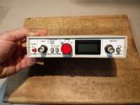
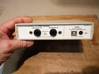
Audio Precision Portable One Dual Domain THD+n problem

Hi All!

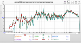
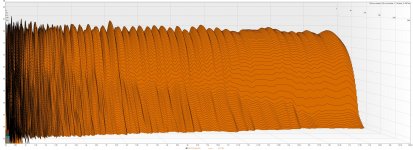
I have a Portable One Dual Domain analyzer that passes all self tests, but after warming up measurements of THD+n start to drift towards -60dB in the 20.5kHz-21kHz (or even 22kHz). When it is cold there is a small step in the THD+n measurements at 20.5kHz but nothing so drastic.

When 20.5kHz-21kHz band is out of whack, everything up to 20kHz is perfectly fine and after 22,23kHz the THD+n returns to "normal". The selftest just misses this anomalous point.

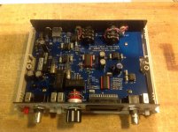
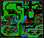
Unfortunately the schematics are not available, but it seems to be quite closely following the design of System One, except that it does not have a 2 stage filter and the null and tune loop seems somewhat different.

I have found equivalent parts from System One service manual in my portable one and I can see that when the problem happens the NULL control voltage goes near the "null opamp" positive rail, so apparently the null error is beyond its ability to compensate. The null control voltage pretty much around +-2V on the 9.5Hz to 20.5kHz range. After that a relay clicks and the null control voltage shoots up to 12V. It stays there in the problem area and just barely gets to 10-9V going further up with filter frequency.

There is another servo loop for correcting filter tuning error and that control voltage is generally in the +-2V range when changing the filter frequency.

My problem is that I currently do not have a good idea on how to do further troubleshooting because of these servo loops. I don't know if there is a problem in the null control loop or the filter is not performing as expected for some reason after 20.5kHz. Or compensation is not working as expected.

So before taking things further apart to disconnect parts of the circuit to see what really happens after the "magical" threshold frequency is crossed, I would like to know if anyone has already seen this behavior.

Obviously other part of the problem is that analog electronics is not my strong point and the details of the filter are reaching far out of my comfort zone 🙂

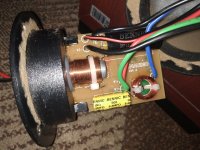
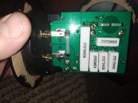
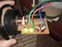
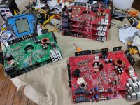
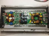
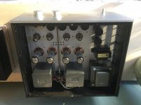
Also before taking things further apart I'd like to know if there is some magic way to easily remove the digital board sitting in the metal can on top of the analog input board. I opened its can but I see no obvious way of detaching the can that is getting in my way of removing the analog input board. So before unscrewing more screws I'd like to know if there is an easy way to get the analog input/analyzer board out

Thanks!
Jaka

Tweeter / Crossover Advice

I came across this design on a Polish website.
It is an MTM design using 2 SB17NAC Midwoofers and 1 SB29RDC Tweeter.
I am thinking of going ahead with this build but would like your expert opinions on two things.
1) Does the crossover design seem ok or could it be improved.
2) Could I use the Satori TW29R tweeter instead of the SB29RDC without any changes to the crossover.
Thanks in advance.

NEP 17k amp

Anyone know what fets I can use in this amp ?

Right now it has IRFP3077 in it but as you can see they are blown and I do not know if they are original since the amp has been worked on before and the originals have been replaced at some point

Attachments

  • 6C170750-23D4-4951-940B-9FD8652F742E.jpg
    6C170750-23D4-4951-940B-9FD8652F742E.jpg
    1 MB · Views: 111
  • E8E27EAE-FD4E-416E-9207-FA86AD4A3346.jpg
    E8E27EAE-FD4E-416E-9207-FA86AD4A3346.jpg
    1 MB · Views: 81
  • A3B661B2-CE19-4E81-9608-1AFBFB563A3E.jpg
    A3B661B2-CE19-4E81-9608-1AFBFB563A3E.jpg
    1,017.8 KB · Views: 78
  • 1E099C3E-6760-4927-8EB3-D4CCDD8C2733.jpg
    1E099C3E-6760-4927-8EB3-D4CCDD8C2733.jpg
    1 MB · Views: 73

Dynaudio DM 3/7 crossover scheme

Guys need help in finding out crossover layout. I can't understand the scheme fully especially in tweeter region.

As far as i can understand woofer works in that way:

An externally hosted image should be here but it was not working when we last tested it.

Attachments

  • IMG_20191126_231418.jpg
    IMG_20191126_231418.jpg
    313.9 KB · Views: 520
  • IMG_20191126_231601.jpg
    IMG_20191126_231601.jpg
    225.4 KB · Views: 519
  • IMG_20191126_231632.jpg
    IMG_20191126_231632.jpg
    299.8 KB · Views: 586

Which amp project for me?

I am looking for my next amp project having just finished my B1Korg
Currently have an F5 and/or a couple of chip amps running my open baffle speakers that are around 95db efficient. Music tastes run from classic rock to blues. Amp only drives above say 100hz as the bass drivers have their own power.
Would like to experience a "tube" like sound and I am considering the Aelph J or the MX2.
Any opinions on the differences between the two or which amp will get me the sound I'm looking for ?

Need buffer for unbalanced line level audio

Good afternoon all,

first post here. I'm coming to this because I have an old HH Scott 340B receiver and I've been trying to get it in top shape. I thought I had an issue with it, but it turns out the real "problem" is an impedance mismatch between its tape out jacks and basically anything I'd want to hook to it. The Scott wants anything connected to have a minimum impedance of 100K ohms, whereas my ADC Sound Shaper SS-412x EQ is 47K ohms. That is enough that just having the EQ connected and powered up, even if the EQ is bypassed, destroys the bass response of the Scott on phono input. I have the same issue with my cassette deck connected directly to the Scott. With nothing hooked to Tape Out, it sounds great, although then I obviously have no line out and can't use the 412x as a spectrum display or to provide two tape loops.

more discussion of the issue here:

Scott 340B weak bass on phono? | Audiokarma Home Audio Stereo Discussion Forums

Posting in this thread as someone suggested a headphone amp might work as a buffer, and I immediately thought of the O2. I sent an inquiry to JDS Labs and got a response that the input impedance was ">10K" when I gave more detail I was told that changing the resistors would work.

"you can see that the input stage is coupled to ground via 10k resistor. Input impedance of the NJM2068D opamp is higher, but the 10k resistor will be a limiting factor. It is safe to assume 10k. You should be able to swap these resistors to 499k if you need a higher input impedance. I have not tested this setup exactly, but would from other experiments we have conducted, there should be little to no impact on overall performance."

I'm assuming he's talking about R14 and R20 and does this seem like a logical way to approach this? I've always kind of wanted to try an O2 but never had a real need for it, if I could use it both for its intended purpose and as a buffer for my tube system, that would be fantastic.

Or is there a much simpler/cheaper buffer that would work for the Scott, and can you suggest one? Thanks much. If using something else would be a better approach, let me know and I'll start a different thread.

FS: P.Millet SoundCard Interface ASSY

I have a Pete Millet interfaces for sale. This is my own unit, built exactly to specs with Front/Back Panels. Unit is in perfect condition. It is working great if you want to transform your computer/laptop into a full function audio test gear. Reason for sale, bought an other measuring setup.

For details see: Soundcard Interface

I'm selling it at USD120 + shipping + 3.5% Paypal fee (for comparison, a new one will cost around USD280 for all the components and materials).

Kindly PM me if interested.
SB

Attachments

  • IMG_20210216_103134.jpg
    IMG_20210216_103134.jpg
    421.4 KB · Views: 247
  • IMG_20210216_103142.jpg
    IMG_20210216_103142.jpg
    408.4 KB · Views: 244
  • SB_IN.jpg
    SB_IN.jpg
    151.7 KB · Views: 251

TPA3110D2 board mods

Hello.Just came to my hands a board like this.After reading the datasheet and inspecting the boards schematic i found that it has a gain of 36dB, GAIN0,GAIN1,AVCC pins are connected together and tied to Power supply voltage through a 10ohm resistor and a decoupling cap of 1uF maybe.

Output LC filters consists of 22uH coils and 1.8uF capacitors.Are theses values ok for use with 8ohm speakers?

Should an additional snubber network of 10ohms in series with 330pf cap be added from each of the class D outputs to ground?

Input capacitors are 4.7uF ,but for 36dB gain input impedance is 9K only and maybe innadequate bass responce.It also has a 1k resistor from each input to ground BEFORE the 4.7u capacitors.I think its better to replace them with something like 47K-100K.

I will change the gain to 20 OR 26 dB.can i replace input 4.7u capacitors with better quallity like MKT or wima?

Attachments

  • TPA3110-XH-A232jpg.jpg
    TPA3110-XH-A232jpg.jpg
    104.1 KB · Views: 152

Ads

Some of the ads on the side bar are reminding me of the old FZ song "po-jama people".

"They all got flannel up 'n down 'em
A little trap-door back aroun' 'em
An' some cozy little footies on their mind"

It appears that the trap-door part is still a thing, nearly 50 years after he mentioned it in that tune!

Transmission Audio ribbon mid/tweeter modules

Helping a friend sell 12 pieces of true ribbon modules, each 38 cm long. Excellent for a long line source ribbon project. They come with transformers. Similar type of ribbons are used on their commercial offerings. Asking 1250 euros for the whole set. New price 800 EUR.

An externally hosted image should be here but it was not working when we last tested it.

ScanSpeak 18W8542-10 bass response in ProAc Studio 100 clones

Hi folks,
I need some help here. I have built a pair of ProAc Studio 100 clones (ScanSpeak 18W8542-10 & Seas 27TFFC), using the crossover schematics of ProAc Studio 1 MK2. Dampening should be fine, all parts are mid/high quality. No matter if driven by a NAD C316bee V2 @ 40WPC Class AB or a Nelson Pass Amp Camp Amp @ 8 WPC Class A, I am not happy with the bass response. Maybe this video might help to understand:


Deep Bass Response Entry 2m vs S100 clone - YouTube


Now I am wondering if something went wrong with my reversely "engineered" crossover. I am well aware of the fact that a 7" woofer cannot do wonders in terms of moving air. And still the outcome now is kind of weak, considering there is a lot more punch and lower frequency energy coming out of my 50 bucks ALR Entry 2ms. Also the drivers might need some time to burn in to sound their best (but I used to own a pair of ProAc DB3s and when they arrived factory new, they did punch a lot more with a smaller driver).


Now I am not sure what to do and was thinking of using a different crossover topology as in Troels Studio 101 MK1 as I was told it is superior to the original one.


Can anyone help here or give me an opinion? Would be much appreciated.


Thanks a lot!


Cheers from Vienna,
Johannes

Duelund Coherent Audio DCA 16GA Premium Audio Cable - 100M Spool

SOLD

Duelund Coherent Audio DCA16 premium audio cable, tinned copper in cotton, oil impregnated.

One of five spools left. My cost was $410/spool ordered directly from Duelund in the Netherlands, ten spool minimum.

Superior to the famous Western Electric 16AWG hookup wire.

Used to manufacture some of the best sounding speaker cables and interconnects anywhere near the price.

Also great for audio construction hookup wire, rewiring speakers/crossovers, etc.

Retail: $800. Yours for $429/100M spool.

Lengths less than 100M are $6.99/M (7M minimum).

Price is firm. No trades. Buyer pays shipping. PayPal adds 3%. Other fee free options.

Thank you.

Attachments

  • SAM_2767.jpg
    SAM_2767.jpg
    628.8 KB · Views: 210
  • SAM_2768.jpeg
    SAM_2768.jpeg
    524.6 KB · Views: 202

B+ voltage not as expected

Fair warning: I'm not the most circuit-savy person, so feel free to roll eyes at my question.

I'm building a tube rectified amp which is a clone of a Decware SE84, but using headphone output transformers. The power transformer is a Hammond 272FX, which uses a center tap on the rectifier heater windings. I'm using said center tap as the B+ which is what the SE84 does.

The tranny is a 300-0-300 output. On the Decware (since sold) I measured 357VDC at the rect. center tap (B+), but on this one, it's 410VDC, which is nowhere near half of the stated output of the tranny. This puts the plate voltage on the output tubes 30+ volts too high. (These numbers are with the amp loaded.)

I should explain that Decware has a DIY circuit board version of this same amp, but uses diodes for rectification, and the spec's for the transformer for that amp is the same as the 272FX (minus of course the 5V output).

WTB: multibit DAC Tube output

I already posted a couple of WTBs in this spirit, but could not find one of them and as I want to open up to other possibilities, I am posting a new one 🙂

So looking for a nice, not too expensive, finished project of a multibit (I am not into the new chips for now - question of mood 🙂 DAC with tube output. USB interface is desired but not a must - good execution is the biggest priority. Hoping I can fins something as budget for a commercial one (MHDT is top of my list right now) is currently not there.

Feel free to MP me

Electronic Flue Gas Analyser

A good day to you at DiyAudio; this is out of the ordinary, I have an electronic flue gas analyser, made by Colwick Instruments Ltd (they are no longer around), it’s called Anagas. The sensor fitted detects CO carbon dioxide only, yet the manufacturer successfully managed to achieve detecting CO² carbon dioxide; I am guessing this was achieved by adding a adjustable resistor?

It would be good to know more about how this was achieved, detecting CO².

You can see the components on my Microsoft OneDrive
https://1drv.ms/i/s!AuQDAPiShOjc2Sru5HJEJIdT1oRK

I am in the process of fitting a new battery pack and a new CO sensor.

CDM4/19 two types of cog-wheel

Hi,
There are two kinds of cog-wheels in the CDM4/19 based drawer mechanisms (see the photos attached): full plastic, supported on both sides (the second photo) and plastic with the metal spindle, fixed on the one side (the first photo). I found the first type cog-wheel in Marantz CD-72 unit and the second type in many other Philips and Marantz units.
In what units are used the full-plastic cog-wheels? Is there a list?
f.

Attachments

  • cdm419cogw.JPG
    cdm419cogw.JPG
    55.4 KB · Views: 208
  • DSCF0021-1024.jpg
    DSCF0021-1024.jpg
    139.5 KB · Views: 195

Boston Acoustics Soundware Subwoofer agonizing coil whine (PSU?)

Had my BA subwoofer for 4 years and it had a terrible coil whine squeal from day one.

I RMA'd it twice, but both times it came back (after a 6-8 weeks return time) and had the exact same problem.
Said they "swapped the amplifier module". As it didnt help, personally I feel more convinced its the PSU module.

Its a coil whine tone, maybe around 4.5Khz. Its terrible agonizing, when worst I hear it clearly 4-5 m from the Sub (because sits in corner).

It wines without PCA input. It whines in both active mode and stand by (inactive) mode, though changes a bit in frequency and often gets noticeably higher when in stand by!

I whines if I move it to a completely other room in the house. Whine makes a weird "squeak squeak squeaaiik" and then dies, when power is pulled.

I opened the sub, not being able to exactly pin point the source. I also didnt see any bulged caps, everything looks normal and smells new.

Fun fact; Im pretty sure the sound dropped dramatically when sub was upside down, being opened up. I have basic knowledge and repair skills like changing dead caps.


Question is: Will I be good with "drowning" the coils (I see at least 2) with eg. hot glue? Or what to do?
Thanks!!


Diagram (I THINK): Box

Inductor Choices

A lot of designs seem to offer ICE inductors or wind it yourself on T106-2 cores. At the moment, due to the stupidity of Brexit, it is hard to get those in the UK and confusion over the new import arrangements have put off companies from selling into the UK.

I can get Bourns, Vishey etc at similar values and currents but wondered if there is any particular parameter that I should keep in mind?

Trying to build my own loudspeakers for the first time. I need help!

Hello everyone!

I am new to this community and just started a loudspeaker build.
It is a 2 way design with a 6" Dayton Reference RS150-4 and a Dayton 1" tweeter with a 2nd order butterworth crossover at 3.5kHz. The vented enclosure is Vb = 14.7L with a 3" flared port Fb = 41Hz.

I took my first measurements using a Dayton Audio EMM measurement mic and am really confused with what I am seeing. I am not expecting a perfectly flat response but I am trying to get it pretty close.

I have attached the SPL measurements of a single loudspeaker at 1M on axis.
I am aware that my tweeter is more sensitive than the woofer and I am making the fix soon. What confuses me is the massive dip at around 180Hz. I am stuck trying to figure out the problem.

I was wondering if it was port noise, resonance, room issues but I am not able to figure it out. Please let me know if any further measurements/info are required.

Thank you

Attachments

  • spl.png
    spl.png
    366.5 KB · Views: 214

Centre speaker locations or alternatives?

I've got a AVR that's great on movies but sucks on stereo music using the on board ESS DAC and pre stage. I want to add a stereo amp which is not great but heaps better on music from a NAS etc and that will supply LF and RF from the AVR pre outs. The dilemma is the centre channel sits on a angled shelf so it fires towards the viewer and do not want to move it above the screen. There's a soundbar in front of the screen so can't add a shelf and lift the screen to place the centre under it as well as the screen would be too high.

The only reasonable option I can see is the place the stereo amp in the AVR location and move the AVR to the left bay. It would be nice to have them both in the centre bay but the centre speaker resides there. In the past I've used 4.1 and also 5.1 with 2 centre speakers beside the screen but not as effective as the single centre speaker which is better for ageing ears. I've also played with the AVR settings and patterns and found no improvement to stereo music and even the Direct mode sucks.

It's for occasional stereo music use as the main stereo stuff was moved and is in a different room.

Before I move this stuff around, somebody might have tried or seen some alternatives.

Attachments

  • RZ_ctr_location.jpg
    RZ_ctr_location.jpg
    90.4 KB · Views: 59

USB interface overloading - Passive attenuator help?

Hello guys!

I've built a phono preamp based on John Broskie's schematic, minus the 12AT7 output stage.
Here is the ('modified') schematic i used:

attachment.php


Obviously its output impedance is pretty high and needs a high enough input impedance on the following stage.
RCA manual states it should be kept above 250kΩ.

Anyway, here's my specific problem:

I've been ripping records using various USB interfaces.
Using a Focusrite 2i2 3rd Gen at the moment, feeding signal into its Hi-Z instrument input (impedance specified @1.5MΩ).

All is good, up to the point I want to rip records using high-output MM cartridges.
For example using a Shure M44-7, even with gain knob at zero the inputs get overloaded and clipping occurs.
It's so bad there's hardly any record I can record without clipping.

So, my question to you guys is whether I could use an unbalanced, passive attenuator?

Placed between the source (as seen in the above schematic) and the interface's input (with its 1.5MΩ impedance).
But, without disturbing the impedance 'matching' too much for the reasons explained above.

A good target attenuation would be around 15-20dB.
That'd be enough I guess to keep levels low enough and not overloading the interface when using my favorite high-output MM cartridges.

It'd be really great if the passive attenuator consisted of a few resistors and the impedance seen by the source be kept above 750kΩ.

Obviously this is above my skills, so I ask you guys.
Hopefully you can help me out a bit.


Thank you for taking the time to read!

Kind regards,
Nikos.

Attachments

  • Capture.JPG
    Capture.JPG
    52.7 KB · Views: 177

Recommendations for a finished TPA3116/TPA3118 unit

Hi, I'm looking for advice on which completed (enclosure, jacks, and all) TPA3118 or TPA3116 unit would be best, preferably for under $100.

I've never used a soldering gun, and I'd rather not mess around with getting a proper enclosure, volume pot, etc., if I don't really have to. Sorry that I'm not taking the DIY route on a place called diyaudio, but I don't have the time right now (maybe some other time?)!

This would be to power a set of Micca MB42X speakers, currently being powered by an Indeed TA2021 Tripath amp. The 3116/3118 units I've found that would seem to fit the bill are as follows

SMSL SA-36 Pro
Yuan Jing TPA3116 2.1 [red board]

I also found this other Yuan Jing unit (with the blue and black board), but I really don't want to pay $115 plus $48 shipping for it.

Any ideas how these finished units compare, sound-wise, or if there are any major problems with them? I couldn't find a whole lot of info on the finished units in particular from the big 3116 thread or on Google. I'm currently leaning toward the SMSL unit because I don't need external tone controls.

Thanks everyone.

EDIT: It looks like the blue board might be able to be gotten to a usable state without soldering: just the DC, RCA, and audio jacks would be needed.
The enclosure and volume pot/knob might be a little more complicated. Hmm..

Converting Linaeum LT1000 from active to passive

[:cop: Thread split from here
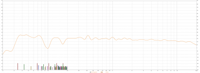
 - Introduction to designing crossovers without measurement]

Folks, this is an amazing thread, and there is literally too much information - making it difficult to comb through.

My question is this:

I have been using a miniDSP 2x4 HD active crossover, and biamping my 2-way transmission line Linaeum LT1000 speakers. I have settled the crossover design using REW with a miniDSP UMIK-1, and listening, and making custom driver EQ filters. These are loaded into the 2x4 HD and I have been listening to it for many months.

The crossover frequency is 440Hz (yes, really) and I am using 4th order Linkwitz Riley slopes. To be precise, the woofer is a 24dB/octave in the 2x4 HD - and the TLS tweeter is an 18dB/octave - and there is a 22uF capacitor in series with the tweeter. I am assuming this is effectively a 24dB/octave slope, as well.

The reason I did this was for our friend Justin Case. I didn't want to risk these tweeters, which are the definition of extremely rare.

*Is there a guide for how I would go about picking the values of parts to build an analog 4th order LR crossover, at 440Hz?

I am then going to need to add a resistor(s) to the tweeter, given it is 1-2dB louder than the woofer, and I am aiming at a so-called "room curve". In REW, I am using the default one they suggested: flat between 200Hz and 1kHz, with +1dB per octave below 200Hz (so a total of +3dB at 20Hz) - and a -0.5dB/octave above 1kHz (so a total of -3dB at 20kHz).

I am intending to build a MLTL cabinet for the Dayton Audio RS225P-4A woofer. I have all the data on these woofers. The challenge is for the needed data on the Linaeum TLS tweeter. I can obviously measure the DC resistance (I *think* it was around 6 ohms?) Do I need additional data to build the crossover?

Any and all advice and information you can tell me, would be greatly appreciated. I have only done the crossover in the 2x4 HD - which I highly recommend, by the way, for this purpose at least. I was highly skeptical of it - but it sounds really good! I think that the upside is that the amps power the drivers directly - the woofer in particular benefits from this, I think. Having the ADC / DSP / DAC stages may seem problematic (I had serious doubts!) but listening has proved to me, that I was wrong.


This is the in-room frequency response and waterfall measured with REW. The dips I think are the 32 year old TL design. I *think* I have got a new cabinet that will eliminate these, and extend the bass quite a bit lower. Which is going to be amazing, if it works as I hope. The Linaeum TLS tweeter is a Paul Paddock masterpiece.

Attachments

  • Response with 440Hz XOver.png
    Response with 440Hz XOver.png
    99.9 KB · Views: 303
  • Waterfall 440Hz XOver.jpg
    Waterfall 440Hz XOver.jpg
    698 KB · Views: 274

SigmaStudio usb

Hello,

I'm having problems connecting a ADAU1701 (Wondom) board to my computer using a programmer board.

When first time connecting, the SigmaStudio label (inside the software) turned green indicating the board was connected. I played around in SigmaStudio and everything worked fine. Then windows 10 tried to install a device driver, an unknown device pops up and the connection in SigmaStudio turns back to orange. Connections fail.

Then after reading forum posts here and elsewhere, I tried installing the CyUSB driver (after removing the device, before removing the unknown device) nothing works. The driver doesn't show up in the device manager.
I'm actually ready to ship it all back.

Anyone else had problems with windows 10, usb3 ports and drivers in SigmaStudio?

Kind regards,
Reinhout

Windows 10, usb3, ADAU1701 (Wondom) with programmer board

  • Locked
Power amplifier PSU SMPS

Hello,

100w ... 300w power using PC power supply transformer 2x30v + + fan temperature control pcb size 100x86mm for more power (400,600,800w) see files

test video (load, short circuit etc.)

IR2153 Audio SMPS Circuit 100W-800W - YouTube

923442d1613570464-power-amplifier-psu-smps-smps-pcb-layout-png


download file;
Just a moment...
Download | file.io
Gofile

Attachments

  • fls.zip
    fls.zip
    3.6 MB · Views: 504
  • SMPS-PCB-LAYOUT.png
    SMPS-PCB-LAYOUT.png
    90.9 KB · Views: 2,755

Reverse engineering Krell KMA 160

I was able to acquire a dead Krell KMA-160 for $0. The driver board of the amplifier seems to have set itself on fire. All the components in the vicinity of the last driver stage have been destroyed, including the transistors, several caps, and a few resistors, one of which is merely scorched, the other if which actually exploded. In addition, a diode in a power supply snubber -- the driver board has a power supply separate from the main power supply -- has exploded. Scary stuff indeed.

What's particularly interesting is there's nothing special about this amp. The topology is unremarkable and the quality of construction screams DIY. In fact the build quality of my Aleph-X monoblocks is, IMHO, quite a lot better than this thing.

Of course, the Krell precedes my efforts by 15 years 🙂

I hope to get photos and schematics up soon. So far I don't see any exotic parts. There's plenty of MJE 15030/15031 driver transistors, as well as A968/C2238 (these are not marked 2SA/2SC but they do have a great big capital "T" printed on the case. Are they Toshiba?) The small-signal BJTs are A970 & C2240 like you might expect. The power supply seems really basic, but I'll report more after I've diagrammed the whole thing.

Oh, and on the back of the board is the gross rework hack. Eww.

Anyone else have experience repairing, or improving, this unit?

Pile of T10001BD to repair

Got myself a project pile of T10001BD amps to be resurrected.

Thank you guys for all this wonderful info!

I managed to get one going from scrounged parts, which was cool, haven't fixed amps in a long time.

I have schematics for most of them, except the older 2005 models.

I was wondering if anyone one knew the part numbers to the switches SW100, SW101, and SW102?

Figured out the 4 gang frequency pot RV101 replacement, Bourn #PTD904-1015P-B203.

All these boards seem to have malfunctioning pots and switches, along with some have let the magic smoke out. Looks like the circuit board needs support in that area to keep from vibrating so badly. Repair first, then modify...

Thanks for your tjme

Attachments

  • IMG20210212162333.jpg
    IMG20210212162333.jpg
    1.1 MB · Views: 138

6.5-8" mid driver for 150-1500hz with high sensitivity

Hi guys, i am planning a 3 way with the PHL 4021 and the 18sound nsd1095 with xt1086 horn. But I am not sure about the mid driver. The crossover frequencies are approximately 150 and 1500. I don't need high spl, but high dynamics and very good transients. It shouldn't cost more than ~300euro.


mid drivers i consider right now are:
PHL 1120
PHL 2460
18sound nmb900 or mb420


What do you think?

Panamax M5400-PM Odd issue

I owned Panamax M5400-PM.
Which has voltage regulator function with
input voltage and output voltage indicator.

The thing is when input voltage is 120v, the unit think it's 110v, so
the unite up-trans 10v. So, output voltage indicator shows 120v but actually it's 130v. I checked with several multimeters.

Basically, the unit always think 10v lower than actual voltage.

There is no adjustment knob or switch to calibrate.
I asked Panamax and they just told me not to use the unit and buy new one.

Do you guys have any idea how to fix it or adjust it?

I ve changed every capacitors, relays, voltage regulator ICs.

Another possible failure components?
or adding some components to adjust?

Gentlon, a Power-Good Driven Soft-Starter

What is GENTLON?
It is an after-the-fuse power entry control board that gently turns on the power to an amp (or other devices).

Is Gentlon not just another soft-starter?

Yes, it is, if one doesn’t care a short list of a few little things more than what a usual soft-starter does, and the way that it does them. Otherwise, the list goes,

1. Power-Good driven: Gentlon soft-starts the power, but does not turn power full on until a subsequent Power-Good condition is established. If Power-Good fails to establish within 5 seconds after soft-start, the circuit gives up and returns to power off (standby) mode.

2. Has onboard Power-Good monitor that watches up to 4 DC rail voltages, 2 positive and 2 negative, detects rail droop/collapse and defeats Power-Good accordingly. The threshold voltages for Power-Good and rail collapse are user-defined (by resistor values).

3. Two wire headers offer off-board speaker relay drive, at 12V/100mA capacity each, also sustained by Power-Good,

4. A wire header offers off-board power relay drive if choose to have the power relays and the NTC thermistors installed elsewhere in the chassis.

5. Accepts speaker kill override.

6. Accepts power kill override.

7. Has on-board bulk capacitor bleeder, fully discharges rail capacitors in seconds at power off. (Can be defeated with a jumper)

8. Allows installing up to three 1-in diameter NTC thermistors, offering generous Joule handling capacity for even "ridiculously" large bulk capacitance on the power rails.

9. Has a NTC cool-off timer that blocks repeated, frequent power-on attempts. It gives the NTC thermistors chance to cool down and come back to normal resistance to help ensure adequate inrush limiting performance at each power-on event.

10. Rev.3 PCB offers relay-switched Neutral connection, in addition to the usual switched Live wire. (Rev.2 PCB does not switch Neutral, but it has a 30A relay.)

How does it operate?
A simplified flowchart:

Gentlon_FloChart.png

Note about the “Plateau”: A time delay placed after the soft-start before probing the PG status. If one wants to probe the PG and shunt the NTC sooner or later this is where to make the tweak. But it is up to 5 seconds, or the circuit goes back to Standby state.

Has it been built and tested?
Built a few Rev.2 Gentlon, all operate properly. I have one of them in a dual mono power amp (Meistersinger amp, my own design and build) with two 600VA toroidal transformers, followed by 120,000uF total capacitance on +/-65Vdc rails, in service for 5 years now. Have never built the Rev.3 Gentlon, but the only difference from Rev.2 is the added option of the switched Neutral, and a 16A relay instead of a 30A relay.

Gentlon_Thru-Ho.jpg

There are loads of SMD parts, can someone new to SMD build it?
Unlike most other SMD PCB designs seen in our forums that simply take standard IPC7351 compliant footprints, I make all SMD footprints specifically suited to DIY hand soldering/reworking. All land patterns in my PCB designs have ample pad exposure beyond the component body for easy iron tip access. The smallest size SMD part used is the large-ish and easy 0805, making the Gentlon a good SMD beginner's project. A usual temperature controlled soldering iron and a pair of fine tipped tweezers would be adequate for assembling this PCB (what I solder mine with). For advanced level builders in terms of SMD experience and equipment, this PCB is also suited to reflow assembly process.

Gentlon_SMD.jpg

What's being shared?
Schematic diagram

View attachment GENTLON_2.pdf

PCB fabrication data package (can be sent straight to a fab house to order PCBs, as well as the paste stencil if desired)

View attachment Gentlon_2_Gerber.zip

BOM

View attachment BOM_Gentlon_2_Raw.txt

An LtSpice power rail monitor schematic for simulating/altering resistor values to suit desired Power-Good voltages and the hysteresis, or the protection threshold. The un-altered circuit validates Power-Good at about 56.5V, and defeats it at about 55.5V.

View attachment GENTLON_2.asc

2. Assembly Options
Some functionality of the design can be opted out.
Don't want the Bleeders? Delete all components in the "Cap Bleeder" box in the schematic, with the exception of the four 10-ohm resistors and J11.

The amp has only one pair of DC power rails to monitor? Connect the DC power rails to J11, delete J10, D10, and D11

Use no more than one NTC? Use a proper resistance value and current rating NTC, delete the other two from the BOM and short their soldering pads.

Power rail on different voltages? Simulate for the desired voltages in the LtSpice schematic and change the resistors in the BOM.

What does it look like when in action?
Gentlon_in_Action
Sorry, ran out of hands...😀

Tweeters too bright

I recently purchased a set of older Marshall speakers with blown tweeters. I could see the 15" woofer is 8ohm but I had to guess for the tweeter. I replaced the diaphragms in the tweeters with 8ohm as well and now that I can finally hear them running they are really bright. I would like to avoid just getting a l-pad to fix it as although they are not super expensive to buy neither were the speakers and if I can I would prefer to just do it with resistors. My question is, can I use REW to analyse it and figure out how many db I need to turn the tweeters down (and from there calculate my two resistors) to get a better sound?

Cheers!

P.S. I am quite new to this and have only just started playing around with REW.

Carver 2000 issue with amp section

I just purchased a Carver 2000 magnetic field receiver.


it works fine until the volume control hits about 10/11 o'clock, then protection cuts off the relays for a few seconds while I lower the volume setting and then its fine until I take it back to 10/11 oclock again


I opened it up and visually it looks fine.


I measured the four largest caps and they seem fine with a standard cap meter


I set the voltage adjust to 69V


then I went to set the idling voltage and it acted weird.
I measured 0 volts on both channels instead of 4.5 but adjusting the two trimmers did absolutely nothing.


does anyone have any suggestions ?


thanks

My best bookshelf speaker.......so far

I thought this might interest owners of the Peerless 6.5” nomex mid-woofers.
I’ve had mine for several years paired with DX25 tweeter and they are ok, but nothing great.
I build some .5cuft out of some red oak boards and sculpted some leather covered mdf baffles after laminating three 3/4” thick sheets together.

Then, during isolation last year, I found an article about the “Distractions” speakers by Robert Dunn who paired the same woofer with Hiquphon OW1 tweeters back in 2012.

Coincidentally, I found a pair of OW1 tweeters, assembled the Distractions crossovers, and replaced the DX25s.

The final combination is the best standmount speaker I have built, along with the Ergo ix, courtesy of James of PFM fame.

This is the only time that I have heard the Hiquphon and it is magical how the soundstage is enhanced, improved imaging and shimmering percussion.

Attachments

  • 047C3B5C-A5A8-45EA-A02F-7B61823326BC.jpg
    047C3B5C-A5A8-45EA-A02F-7B61823326BC.jpg
    553.4 KB · Views: 516

6SC7 Phono pre amp

I built this pre amp mule while ago, and recently dug it out, rebuilt the PS and added a second channel,,, Played a couple dozen albums and find it to be a little lacking in bass response with a TechnicsSL-D30/P28,,, it seems to respond better with the Dual 502/Shure M91E...
I want to try a different coupling cap, replacing the .0047 to .0068 or .01 or so to see if there is any boost in the bass response...

Question is,,, Will changing that cap change the EQ of the pre amp? How about if the 22M grid resistor is left in place?

Some searching turned up this post,,,
"I noted that in the Tronola articles, the coupling cap in an Eico phono section was changed from a 0.05 ceramic to a 0.1 µf film cap. This made sense and improved the LF response. So sometimes it is beneficial",

Para phrase from...POST #15
http://audiokarma.org/forums/index....or-values-in-tube-amp-preamp-rebuilds.744091/
Any thoughts from the designers out there!!
Thanks for any info,,,

Attachments

  • P9090002.JPG
    P9090002.JPG
    79.4 KB · Views: 952
  • P9110012.JPG
    P9110012.JPG
    81.3 KB · Views: 907

Successful TU-8600 300b Build

Hello All,

I completed my Elekit TU-8600. I opted for all of the optional upgrades through Victor. Here is a summary of my experience.

This build was a bit more involved than the 8200, but not much. The board layouts were superb and made a lot of sense.

It was a bit slow going in the beginning when I had so many open slots to populate; as the main board began to fill up the pace picked up because I had less searching to do to locate the next spaces for placement.

I needed Victor's help on this one (not on the 8200). He was amazing. I felt that I made a friend. He calls and emails promptly. His passion for the hobby shines right through.

My left channel was not working upon completion. I had to go back through each and every solder because I could not locate the issue. I reheated each solder on the left channel. I also went at the solders that were close together and cleaned up the space between them (regardless of whether I could see much if any solder) to eliminate any shorts. I also took the main board out completely and flipped it and checked each and every through hole placement, etc. After about 4 hours of this I set everything back up and voila!-music out of both channels.

The amp sounded great out of the gate, yet a running in of 90 hours this week (night and day playing) has improved things more.

I have two issues to address. First, I'm getting a ever-so-small static crackle when I move the volume knob at higher volumes. I'm thinking that I need some insulation/gasket between the Alps pot body and the knob spindle to reduce static electricity. My Alps 100k didn't come with any nut or locking washer. Maybe that will help?

The second issue is paint color. I think that I will paint the unit for living room display in the future--maybe an automotive finish in a vintage color.

This amp is amazing. As Victor says, it places vocals front and center. I love, love love it with jazz. I have a pretty substantial main tube based stereo (~$20k). The 8600 sounds different in a good way. It draws me in much more and has even less listening fatigue (keep in mind my main system is all tube based and is of great quality making it low fatigue to begin with).

Last night I listened to some pretty popular albums--Vince Guaraldi's Charlie Brown Christmas and Muddy Waters (Buddy guy on lead guitar) Folk Singer. The sound was intoxicating.

I cannot find any fault with this kit or the end result. The only thing I would like to see is a second input so I can run a turntable/phono pre and a digital input.

If I can build this anyone can! Go slow and enjoy the process. It's a zen-like thing to build one of these.

Special thanks to Victor for all his help and sharing in the passion! Victor, you are the man!

Looking for a Dayton SPA-250 schematic

Not sure if this the right place but here goes... I have had four Dayton SPA250 Plate amplifiers over the years and they all fail after a while, usually five years down the road. They just blow the fuse and go dead.


I was wondering if anyone knows where I can find a schematic for the amp to see if i can get any of them fixed. I contacted Dayton and they would not provide me with one.


I guess I shouldn't complain too much as these amps seem to last for a while. My two SPA500s and SPA1000 are running about 10 years old and still going strong. My Polk subwoofer and Velodyne amplifiers had failed at only a couple of years.


Thanks in advance...

Sources and thoughts on transport buttons?

Working on my first project and I'm looking for a set of transport buttons. Searches at Mouser and DK haven't turned up anything.

I love the vintage look and feel of the ones on my Akai R2R - but assume they'd be either proprietary or NLA?

In a much more contemporary vein, the Arturia KeyStep has nice, soft internally illuminated buttons about the right size.

Any sense of where to get these sorts of buttons?

Thanks in advance!

RK

Attachments

  • AkaiButtons2.jpg
    AkaiButtons2.jpg
    399.3 KB · Views: 108
  • AuturiaKeystepbuttons.jpg
    AuturiaKeystepbuttons.jpg
    828.6 KB · Views: 115

Step-up transformer comparison

Recently I opened a new topic about my stats lacking bass punch:

Lacking of bass "punch" in my esl's

I got a lot of insightful replies. One of them was this one by bolserst:

Lacking of bass "punch" in my esl's

This post lists a few possible causes that contribute to the experience of "lack of bass puch" in stats, one of them being: step-up transformer compression/limiting.

I still have to continue reading this topic and doiing my research, but I started to measure and test my current three different pairs of step-up transformers:

1. AudioStatic 2x1:75=1:150 step-up
2. DIY #1: 1:120 step-up
3. DIY #2: 1:90 step-up

Transformer #2 end #3 were made by two different local hifi-enthousiasts.

In the attachements you will find:

* a saturation comparison. I put a 2 ohms resistor in series with the transformer and measured voltage across the resistor in order to calculate current. Voltage across amplifier output on x-axis, current through transformer is on y-axis (I put a wrong label on the x-axis). I measured with a 10 Hz sine-wave.
* an impedance comparison of the transformers (without load / esl)
* an frequency response comparison of the transformers

It seems the 1:90 transformer has both the best (highest) impedance and the best saturation behaviour. The AudioStatic has the worst saturation behaviour. The 1:120 DIY has the worst hf frequency range and a promlematic impedance. So at the moment I prefer / use the 1:90 DIY transformer on my current stats.

The next step would be to make a circuit which turns on a LED when saturation current is reached just to check if the transformers do saturate when playing music.

I will keep you informed.

Attachments

  • transformer saturation comparison.png
    transformer saturation comparison.png
    67.1 KB · Views: 365
  • transformer frequency graph comparison.png
    transformer frequency graph comparison.png
    82.8 KB · Views: 348
  • transformer impedance comparison.jpg
    transformer impedance comparison.jpg
    162.8 KB · Views: 352

FS: Doug Self Preamp Linear Audio 5 PCBs

Hi!

I have a set of PCBs for the preamp from this very popular thread:

https://www.diyaudio.com/forums/analog-line-level/280458-doug-self-preamp-linear-audio-5-a.html

Unfortunately I don't find the time to build it and I have to many projects in the pipeline.

I'm based in Europa but can ship them anywhere in the world.

I paid 50 USD + shipping.
You can have the PCB kit for 35 USD + shipping.

KEF B139 as subwoofer

I have a couple of these, which I could either sell if anyone is interested, or otherwise build subs with. I don't have space for a TL, so the sub would have to be IB or ported. Can anybody point me to a functional design that's as small as possible? I don't mind flat to 40hZ - don't listen to organ music and low E on the double bass is the lowest note I'm interested in. Thanks for all suggestions. Andy

Volume control of TAS5754 based amplifier

I have purchased this board - [wiki=https://store.sure-electronics.com/product/AA-AB32256]%[/wiki] - from Sure Electronics. It is based on the TAS5754 and is attractive in that it has an I2S input.

It also has an I2C input which I mistakenly thought led directly to the I2C port on the TAS5754. As I wanted to control the amplifier - and in particular - the volume from a microcontroller, this seemed ideal. However, the board I2C terminal leads to a microcontroller embedded on the board. Sure Electronics sells a volume control for it, but to have more general control possibilities I need to be able to generate the I2C signals myself. These seem to be a state secret.

My first question is: does anybody know where I can find out how this particular I2C port works (e.g. The I2Cs address, what data needs to be sent etc.)?

I have asked the manufacturer. They seem to imply that I can change the volume by adjusting the voltage levels. I’m assuming that this is the power supply (e.g. high volume = powered at 19V, low volume = powered at, say, 5v). I could then use a variable voltage regulator (suitably rated) and adjust the voltage (0 volume) using a digitally controlled potentiometer.

Is this a technique that could work? Are there any gotchas that I should know about?

Many thanks for any hints.

KSL Kondo Overture

Audio Note Japan KSL KONDO OVERTURE.

From 2011 and in absolutely ‘mint’ 10/10 condition. U.K. spec. Comes fully boxed, KONDO certificate signed by KONDO President Masaki Ashizawa, spec sheet and all relevant paperwork. Musical presentation is as beautiful as the aesthetics and engineering are exquisite.
This item is only for sale in The UK and is collection only from Harrogate, North Yorkshire. I simply would not trust any courier with the transportation of this fabulous amplifier. Psvane Phillips replica EL34’s are currently fitted and sound wonderful.
I realise collection in the current conditions are not favourable, though perhaps not impossible. However, so folks can give it due consideration, I’m posting this lovely amplifier for sale nevertheless.
I am relatively new to The diy audio forum, though being a ‘box swapper’ have a long history on U.K. forums.
I don’t have a PayPal account so it is payment by bank transfer. New price for Overture is a whopping £30.000. There are a couple more Overture’s for sale in The EU, this being the cheapest by quite a big margin. I am asking £9400.00 or close offers. At the asking price, I will also include a Quad of unused NOS SIEMENS EL34’s circa 1980’s.
Photos are of the actual Overture. I’ll post a pic of the rear of the amplifier when I find a minute. As this is a ‘For Sale’ thread and not a ‘Discussion Thread’, far better to discus via PM’s rather than on ‘open’ forums. Serious enquiries only please and by PM. Think that’s everything.
Thanks for looking. Mark.

Attachments

  • 8764E812-2895-4703-85A6-18B6346F6000.jpg
    8764E812-2895-4703-85A6-18B6346F6000.jpg
    654.1 KB · Views: 834
  • 89766D73-FC00-4370-8628-D4A099302CCF.jpg
    89766D73-FC00-4370-8628-D4A099302CCF.jpg
    635.6 KB · Views: 828
  • 04368772-07C7-433D-895D-097E09F2C47A.jpg
    04368772-07C7-433D-895D-097E09F2C47A.jpg
    676.5 KB · Views: 802
  • 1E236290-B9AF-4694-8534-4E2F10F34F4A.jpg
    1E236290-B9AF-4694-8534-4E2F10F34F4A.jpg
    644.4 KB · Views: 813

FS: Parts kit for Zaph ZA5.3c center channel (USA)

Zaph|Audio ZA5.3c Center Channel, Single
za5.3c
Options:
Accessories : Ported Enclosure Accessories Package
Crossover Version : Traditional Boxed Speaker Design
Tweeter Cap : Bennic XPP
Binding Posts/Input Cups : DB-CUP [Qty 1]

Full parts kit, brand new. Includes:
Included:
(2) ZA14W08 Aluminum Cone Midbass Woofers
(1) DQ25SC16-04 Titanium Dome Tweeters
(1) Professionally Assembled Crossovers
(5ft) Supra Classic 1.6 (15AWG) internal speaker wire
(2) 1.5" x 4" PT-F415 port tubes
(1) 27" x 42" x 5/8" Foam Sheet for lining the internal walls
(1) GOOP adhesive to glue foam to walls
(1) QC110R for + tweeter tabs
(3) QC110B Quick Connects for – tweeter & - woofer tabs
(6) QC187R Quick Connects for + woofer, + crossover & + binding post tabs
(4) QC187B Quick Connects for – crossover & - binding post tabs
(12) #8x1 Black Ox & Wax Socket Head & Wood Screws for mounting drivers to baffle

$140 shipped to lower 48 states

Paypal for payment

Mycelium speaker

Hey guys, I'm new here so excuse me if I'm posting this in the wrong sub.

I'm an industrial design student from the Netherlands working on a project in which I'm designing products with a new sustainable and biodegradable material called mycelium. It is a composite of fibers and fungi roots that is comparable to MDF except it has a lower density (I like to call it LDF). You can view it as a low-density MDF material that replaces the epoxy with fungi to hold the fibers together.

It has some interesting material properties that make me wonder if it's suitable for building speaker cases. It has naturally sound-absorbing properties (This might be a downside as well) and it is great at dampening vibrations, reducing problems with resonance in the case. It can also be grown in a mold, allowing you to make more complex shapes that might be interesting for base ports and the design in general.

I am no audiophile however, I am interested in a subject. Do you guys think this might be a relevant use case? What are the pitfalls? Should I approach a speaker manufacturer, and so can you recommend any in the Netherlands?

Thanks! Yvo

Edit: I am currently looking into transmission line speakers since it seems like making one from mycelium might be advantageous from a production point of view. Currently, transmission line speakers have to be CNCed which is an expensive process. Using mycelium grown in a mold might be a good solution. What are your thoughts on transmission line speakers? It seems like an outdated idea, what are the advantages/disadvantages?

Clarion amp, not powering up

Hi all, trying to repair a Clarion Apa4300 amplifier.
When attempting to power up the digital panel lights up,
The power on led stays off.
No audio output.

On internal inspection Q143 tested 0 ohms across all 3 legs so I removed it along with Q144

I've tested TL594, all measurements in DCV pins 1-16
1, 0
2, 4.9
3, 0
4, 0.1
5, 1.5
6, 3.6
7, 0
8, 12.9
9, 6.2
10, 6.2
11, 12.9
12, 12.9
13, 4.9
14, 4.9
15, 4.9
16, 3.5

Also checked dc voltage on Q812

1, 12.65
2, 13.6
3, 13.3

Apologies I had already started a post on this amp but my meter was on the wrong setting leading to much confusion so I've started a fresh thread.

Hopefully I can get the amp up and running again, and thank you Perry for your patience and support.

Passive Radiators in Front L/R 3-ways???

Silly question #3

Is it a bad idea to go with an 8" woofer and either 2 x passive radiators (or 1 bigger PR) in normal floorstanders?

I like the idea of not having a port (chuff chuff) but I haven't seen any DIY 3-way floorstanding projects with PRs.

2nd question

Is it a bad idea to have an 8" driver, an 8" PR on the same baffle facing forwards and another 8" PR on the side?

Thanks

Any links to floorstander projects with PRs would be good. I've tried searching but the forum search seems to return 100s of threads not relating to the search term!

What is killing my MOSFET (Tube CCS)

I have been trying to build the CCS according to the schematic found here:
diytube.com • View topic - EZ Sink: Depletion-mode MOSFETs and the LM334

LM334 is configured for 7mA.

First attempt, I built the circuit, connected it to the 6SN7 plate, applied 250V B+ to the drain of the DN2540...and poof. No more MOSFET. Basically have an expensive resistor.

Thinking there was some issue with the way current is applied from the cathode warming up, I subbed the tube for a 1000 ohm resistor as a load. Ammeter shoots up to about 15-20mA...and no more MOSFET.

To check that I have the LM334 configured correctly, I remove the MOSFET from the equation. I hook up the LM334 to one of my low voltage bench supplies, using it to source current to the same 1k resistor, and it behaves as intended. I get a constant 7mA from the max voltage of the power supply down to the dropout voltage of the device.

I pop in another DN2540 (source connected to the V+ of the LM334, gate tied to the V-, and consequently, the load) in circuit, and the MOSFET fails once again.

I've been testing the DN2540s cascoded as a CCS for about a week prior and outside of one oops, they had been performing admirably in the exact same role. My goal with the LM334 was to be able to have a repeatable current reference vs the variability I had run into with using a current set resistor (I was just using a trimmer to get the current set) based on whatever the Vgs was of the particular 2540 I had plugged in at the time.

I'm about to pull what is left of my hair out over this. I'm down to a single good FET now and really don't care to destroy it...however it is managing to happen. Any ideas?
Projects by fanatics, for fanatics
Get answers and advice for everyone wanting to learn the art of audio.
Join the Community
507,789
Members
7,888,656
Messages

Filter

Forum Statistics

Threads
406,250
Messages
7,888,656
Members
507,789
Latest member
flipzbird