Denon PMA-757 problem with the source

Hello guys. This is my first post, but I am a stalking the forum for quite some time. So, I have a Denon PMA-757, and I am having some problems with using my phone (LG V20) as the source. No matter where I connect it (DAD, PHONO, VIDEO/AUX) with a simple RCA to aux cable, I get severe distortion and almost no volume. Same happens with the speaker outputs. However, my dad initially used a Luxman T111L Tuner as the source, and it works like a charm, both with headphones and speakers. What could be the cause for the phone combo not working?

P.S. I hope I am posting this at the correct section of the forum

FS: Scanspeak 15w8530k01 and cabinets

Another Covid project for sale.
All drivers in great shape. 3/4” Peerless tweeters are fitted, cut-out will accept other tweeters with 94mm dia faceplate, such as Hiquphon OW1 and Morel CAT378.
Enclosures are 9L, 12x7.5x10, same frontal size as LS3/5A. Removable back.
3/4” mdf with vintage 1.5mm teak veneer. Glove leather covered baffle.
No crossovers. I used minidsp.
I will sell with or without the Peerless tweeters.
$290 with tweeters.
$260 without.
Plus shipping.

Stay safe,
Peter

Attachments

  • 7911977F-72C9-41AA-B595-C73846D06352.jpg
    7911977F-72C9-41AA-B595-C73846D06352.jpg
    864.1 KB · Views: 318
  • D9CD7872-4875-4157-A39E-D4B9BC9895C0.jpg
    D9CD7872-4875-4157-A39E-D4B9BC9895C0.jpg
    974.2 KB · Views: 295
  • 5C3AD696-F07D-4E1F-9407-3A536D2DDCB5.jpg
    5C3AD696-F07D-4E1F-9407-3A536D2DDCB5.jpg
    482 KB · Views: 282

TU-8000s tyvm Victor

Up and running a few weeks now with the TU-8600S.

When I put it together it would not power up and test voltages were off. I was in a state of semi panic/despair - I am no more a real DIY'er than someone who follows a recipe is a chef 🙂

Just wanted to say thank you to Victor. First for the good advice and fairly priced parts. Then when things didn't go right, he was kind enough to reassure me that "it would get figured out". I ended up sending the PC board to him and he did indeed figure it out. I think I had missed a resistor by the power LED. Funny how I can stare and stare at something and just not see it.

It's sounding lovely, it was overall a great experience and so thanks again.

Attachments

  • elekit.jpg
    elekit.jpg
    978.5 KB · Views: 173

mc-13s negative feedback

I see that the output transformer has taps that goto pin 4 of the El84 B tubes, and from my very basic understanding is that this helps reduce distortion, but some say does not sound as open.


Again, I'm trying to learn as much as I can and not sound like a total noob... is disconnecting that wire from pin 4 of the El84b's all thats required to stop ultra linier mode?


From the schematic it looks like if I wanted to add a switch I would need a 4 pole single throw switch?

Attachments

  • 10747450.jpg
    10747450.jpg
    161.6 KB · Views: 195

FS: 2x Avel Lindberg Toroid Transformers (30VA, 230V primary, 9+9 secondary)

I have a pair of Avel Linberg transformers for sale (Y236101 - 30VA, 2x 115V primary, and 2x 9V secondary).

Were used in a power supply for a DAC, which has since been decomissioned.

$25USD each + shipping

The items are located in Australia, so be wary that overseas postage may be high.

Attachments

  • IMG_20210202_104920.jpg
    IMG_20210202_104920.jpg
    433.9 KB · Views: 153
  • IMG_20210202_104926.jpg
    IMG_20210202_104926.jpg
    418.2 KB · Views: 157

Can you recommend a good AC/ noise filter juntion

I should be able to successfully pull one off with a little direction. To replace the cheap power bar I'm currently using.

I already have some parts including Hubbell wall receptacles, Hubbell male plug and cord (line to wall). Plywood, heavy guage stainless to add a little bling. And pretty much every guage in copper wire.

I will limit mine to two maybe three receptacle junctions (two inputs each).

I could use some advice on weather to include adding parts for a "noise suppressor" to filter AC routed to cable box DAC and disc player. Basically all source outputs.

I'm not even quite certain I want/ need a "noise" suppresser filter in it. Options on that are welcome.

Something that's effective in its simplicity is what I'm really after.

The Hazard, Or Lack Thereof, Of Thoriated Tungsten Put to Rest

I am hoping the knowledgeable members of this forum can clear something up for me once and for all, the "danger" of thoriated tungsten filaments.

I am working on an 801A A2 design, I laze about a few different audio forums. Whenever it comes up in discussion, I am warned about my radioactive triodes.

My understanding, and please correct if I am mistaken, is thorium is mildly radioactive, an alpha emitter. Alpha particles cannot penetrate skin and the hazard exists only via ingestion, particularly inhalation. I've noted that thoriated tungsten welding rods are still in use, and it is simply recommended that protection be used when being sharpened due to dust exposure.

I cannot see how an 801A, 845, 211, etc. could cause similar hazard when isolated in a glass bulb.

Can someone clarify if my understanding is accurate? Am I going to grow a third arm sitting a few feet from my amplifier? Thank you.

Edit: further reading, the CDC states that alpha particles pose no danger when outside of the body as they can only penetrate 1 inch of air. I may have answered my own question 🙄

Peavey Bass amp upgrade and/or repair.

I have a friends Peavey MAX112 bass amp in for repair. If you look at the power supply segment that I posted, 15V zener diode D9, (of the +/- 15 VDC section), shorted out, and C32 blew it's little pressure relief scoring. They also put a pretty good "burn" on the circuit board. Fortunately, it's just cosmetic. No real damage. D9 is a 1N4744A, that's only rated at 1W. Even though the +/- 15V supply is only powering three small op amps, (2x4560 and 1 LM3080), it seems like a somewhat cheesy way to make a bipolar supply.

Mouser was out of the 1N4744A's, so I ordered two of the 5W versions, plus two new caps.

So my questions are:

1. Do you think the upgrade to the 5W version will give a little better reliability and durability?

2. Would I improve the situation by going ahead and adding a true voltage regulator scheme in its place? I enjoy projects and this amp used to be mine. I'm just not sure if I should connect the 78/7915's after that 250 ohm resistor, or connect it differently. The raw 35 volts is right at the upper limit of what those 78xx series like to see.

Any advice would be appreciated.

P.S. This amp does use a nice LM3886 "Overture" amp IC for power. I was surprised to see that.

Attachments

  • Peavey_MAX112_Bass_Amp.png
    Peavey_MAX112_Bass_Amp.png
    27.4 KB · Views: 202
  • Peavey_MAX112_Bass_Amp_mod.png
    Peavey_MAX112_Bass_Amp_mod.png
    33.3 KB · Views: 163
  • Peavey_MAX112_board.jpg
    Peavey_MAX112_board.jpg
    202.2 KB · Views: 201

Rectifier voltage

Hello there,
I am tackling my first point-to-point DIY amp project with the JE Simple 45/2a3: JE Labs Arkiv (up to 2008): JE Labs Simple 45/2A3

The author kindly helped me with my choice of transformers, however I still have an open question.

My choice is now between a full set of Edcor (XPWR271 power, CXC125 choke, GXSE15-5K OPT) or a full set of One Electron (BFT-1B power, PRC-2 choke, UBT-2 OPT) iron. (There is a $300 difference between the setups but if it's worth it I might still go with One Electron.)

The question I have is that the schematics call for a 600V secondary, while the BFT-1B has 770V and 520V terminations. The author said I could use the 520V taps for the rectifier. Even though tube designs allow for a 5-10% error, that still seems quite far from the specs (13% less voltage).

What would the consequences of an under-fed rectifier be? Could I get the desired B+ by modifying the resistor values downstream?

Alternatively, is it advisable to use the 770V terminations with drop-voltage resistors? I think I have read about side effects of this approach, but I'm not sure.

Thanks.
gm

Steinberg/Yamaha UR22 repair.

I hope someone with more knowledge than I can help me out on this.

I bought this as not working on one channel. Various problems have been noted, with a couple of fried opamps and switches, parts for which are on order.

I have a vague theoretical knowledge, but am a bit stumped by some components which test as diodes but as they're terribly small SMD they haven't enough markings to allow me to replace them. The same with some possible BJTs, marked 'ABL' and 'CBG'.

I've drawn out the circuit from just beyond the input, to the opamp where both channels meet, as far as I can make out. I wonder if someone can look at it and tell me if it looks like a real circuit, or if I've misinterpreted some component type. This is for one of the two channels, with the 10k pot being the gain control.

As I'm getting different DC readings for both channels, I am trying to work out where the current is flowing when it shouldn't but can't replace components if I don't know what they are! If this circuit looks legit (perhaps a differential amplifier, though I'm guessing here) at least I can try dropping in some BJTs and checking the DC levels.

Attachments

18V SMPS 300VA.

This is to power tools normally running on batteries from mains 240V/120V AC.

Is there a SMPS compact enough to fit in a battery body like a 18V 5Ah battery for Ryobi power tools.
I am not sure about the power requirement, 300VA is just a wild guess estimate, I do not know the peak Amp of these tools. What do you think ?
I do not need the usual qualities required for audio.
I mostly need ruggedness.
A PSU made of a main power transformer and a 40A diode bridge would work, but too large and too heavy.

Bluetooth Modules and Ground Loops

I've been looking at Bluetooth modules for my projects. Modules like this Sure Electronics AA-AB41136 Bluetooth 4.0 Audio Receiver Board aptX +EDR 12 VDC sure are tempting. They're cheap and look like they're real easy to use. But I've read a lot about ground loop problems with these types of boards. It seems like the go to solution is to use audio coupling transformers, which I am not going to do.

I realize that a board like this probably doesn't isolate clean and dirty grounds. Combined with haphazard installation this could certainly create a ground loop problem, I would think.

Using a separate transformer winding to power the board is an obvious solution, but not usually practical. I presently have this Dayton Audio BTR01 Bluetooth Audio Receiver with 24-bit/48 kHz Optical Coaxial RCA Outputs which provides adequate service with no ground loop problem, but it's powered by a wall wart. As a DIYer, I obviously want to integrate the Bluetooth function into my preamp.

So I'm asking you to please share any experience or advice you have on this topic. Personally, I suspect that if I install it with my usual methods then I won't have the problem. I suspect that many people on the Web just don't know how to correctly wire audio circuits for low noise and distortion.

Thank you.

Jamo E875 - Replacing speaker driver

Hi gang,

Long-term lurker here on DiyAudio (on my phone normally). I apologise if this is in the wrong section.

I picked up some second hand Jamo E875 speakers in Australia but one of the drivers don't have it's cone piece anymore and is completely exposed.

I'm unable to find any direct replacement part for it - would anyone have any other recommendation on what could fit as a replacement?

https://i.imgur.com/ZMNBKyY.jpg

Thanks,
Hein.

Remote controlling computer audio

I need a way to enable others in my household to access and play music from my MacPro (not a laptop).
Background follows...

Technology

Mine

MacPro macOS
11.0.1 Big Sur​

My wife's

iPad Pro
iPadOS 14.2​

Stereo system

MacPro has a hardwired digital connection to my stereo system's Hypex plate amps with DSP.
As it stands the system has no other available inputs (wireless or bluetooth) into the stereo system.

So, I can not send music directly from any other device to the stereo system. The stereo has no other inputs remote or otherwise.

I use Apple's Music app. Works perfectly.

Goal

Enable my wife's or other's iPad Pro to remotely access my Mac Pro's Music app. So she can play music on the attached stereo system.

Note: She has a different AppleID than I do, but I would think a way must exist to permission her to control things.

I use Apple's Remote.app on my iPad to control the stereo when I sit in my listening spot (away from my desktop), but I can't figure out how to make this work from my wife's iPad.

Thoughts and guidance appreciated.

Linn lk-85

Hi i was looking at the part list for the lk-85 complete list of all components and was comparing the it to the parts in my lk-85 and i spotted 3 transistors that dont match , they are the input transistors C1SSB on the part list it says they should be 2C4391

can anyone help me find info on these C1SSB SMT transistors should i change them for the 2C4391

thanks

For DSP theory nerds: help me understand LMS decorrelation?

Hey folks. I've found this thing that I think is interesting, and I'm trying to understand how it works. I think DSP is fun and cool, but don't have any education in the how-it-works department.

Here's the thing:
Stereo to 5.1 Channel Converter in Max/MSP

I'm particularly interested in the LMS-based upmixing section, mostly about center channel synthesis. I wasn't able to download the MAX patch from the link, but but I was able to recreate the important bits in MAX, once I figured out the gen~ function. I emailed the author about the broken DL link, but no response.

(Max / MSP What is Max? | Cycling '''74 pretty cool tool for sound monkeying on yer computer. Free evaluation.)

From the link:
"The least-mean-square (LMS)-based method uses a decorrelation technique using the LMS algorithm. One of the original stereo channels is used as the desired signal d👎, and the other is considered as the input, x👎, of the FIR filter. The output y👎 represents the correlated part, which is used as the center channel, whereas the error e👎 that is the uncorrelated part is considered as the surround channel."

So I though that center channel y👎 would contain the common content and I could subtract that from the L and R channel (and double it) and play
(Left only content) - (L/R common content) - (Right only content)
across a 3 channel front and it would be cool.

But it doesn't work like that. Why? I made a patch with a tone generator with a L/R panner on front feeding into the modified LMS upmixer (ctr subtracted from L and R), running into a set of meters on the upmixers output, and it doesn't seem to function like I expected. (It doesn't seem to work right on listening to music either.) In fact, the REAR channels are set up as Left minus Center, hmmm.

Trying to figure out how it works leads me to more detailed questions, but I figure I'll try to get some educated individual to take the bait here before I spend a lot of column-inches laying out my ignorance. This is already getting into TL-DR territory.

Anyone out there interested in explaining this thing?

Wiring a Planar

I had some magnets left from earlier projects, so I made this contraption for fun.
Its a bass driver with nine rows with 19 magnets in each row. The magnets size is 4x10x40mm, and a 12Um Mylar sheet stretched 4 mm over the magnets.

The perforated metal is a shelf from IKEA called "Bottna".

Today, it has four loops of 0.32 (28 gauge) copper wire. Each loop has four turns in the magnet gap. The loops are connected in series, giving a total of 5 Ohms and sensitivity around 85 dB/2,83 volt

The wires are taped to the Mylar using Kapton tape for easy replacement. (works surprisingly well, with very low distortion)

The big question: How to make the most Spl efficient wiring? Maybe using thinner wire in parallel?

Any suggestions?

Regards/ Jonas

Attachments

  • IMG_1655.jpg
    IMG_1655.jpg
    661.4 KB · Views: 605
  • IMG_1656.jpg
    IMG_1656.jpg
    513.7 KB · Views: 589

Happy customer ?

I recently sold a USB PC oscilloscope pcb on ebay.
Got an email and it said he was very happy with the scope after fixing all the dry solder joints !

I have been soldering for 40+years.
I have a Radio, TV, electronics examination board pass in practical electronic skills from 1981.

If it was so bad how come it was fully tested and worked ok for me ?
I can only guess the electrons were jumping the gaps ?

Two chassis preamp grounding

I am building a preamp with a separate power supply chassis. I searched for threads discussing this topic, but didn't find one that was a good match to what I am planning.

My power supply chassis will have a custom transformer to drive four dual-rail supplies (filtered, but not regulated) for analog circuits and one single-rail regulated supply for digital circuits. The IEC ground will be connected to the chassis ground. I am currently planning a 14 conductor umbilical so all supplies will have their own ground connection, so all these supplies will be floating with respect to chassis ground and to each other.

The preamp chassis will use four dual-channel UltraBib regulators - two for each channel (one supplying +/- 17v for Salas DCG3 amps, and one supplying +/- 10v for op-amp circuits).

I'm assuming I want to have a single star grounding point in the preamp chassis to provide a common grounding point for each of these separate circuits. Do I need to somehow connect the preamp chassis ground to the PS chassis ground? If so, I assume I will need a 15th conductor in my umbilical and connect through a ground-break circuit, but I'd rather avoid this unless it's really necessary since I'd have to use a bigger umbilical connector.

Thanks.

How to connect headphones to power amp output

When some simple power IC project is finished people often need to connect headphones to it. There is more than enough power and in that way one does not need to build separate headphones amp, saving hardware and work. I compared several schematics used by Japanese companies and noticed that usually headphones output is connected in parallel with speakers output using just one series resistor in the range from 220R to 680R rated 0.5W or 1W. This is simple and indeed works quite well in practice. There is one downside that phones are driven from high impedance and that creates some frequency irregularities. Is there better way to connect headphones in parallel with speaker outputs. Would it be better to use two resistor voltage divider which will have impedance matched to the impedance of headphones? Any ideas?

Help building high pass crossover

Hello,
My first post for home audio. I currently have dual 4-10s made by Tekton. I'd like to high pass these speakers to work from 50hz into a 4ohm load maximum rms by amp 300watts.

The Tekton Design 4-10s have a low pass crossover up to 200hz. So, I'm thinking I could crack open the subs and add a passive high pass from 50hz. That way the subs will be bandpassed from 50hz to 200hz. I'm thinking a 12-24db crossover slope would suffice.

I'm looking for hows to build my own. Parts and diagram if you'd be so gracious to help out?

Overview: I have Tekton Design Ulfberht mains. And I have dual 4-10s which I'd like to bandpass. I'm looking to add dual subs from 50hz and below and is why I am here inquiring on how to passively dual bandwidth the 4-10s.

Much thanks in advance,
William

IRFP240/9240 Amplifier (simulated on TINA)

Hello guys,

I modified a MosFET based 100w amplifier, I'd like to know if the resulting simulation is good enough for an actual build. Any thoughts?

Many Thanks!

Attachments

  • VERTICALFET_AMP.JPG
    VERTICALFET_AMP.JPG
    90.2 KB · Views: 3,820
  • VerticalFet_AC_Transfer.jpg
    VerticalFet_AC_Transfer.jpg
    51.4 KB · Views: 3,593
  • VerticalFet_Transient.jpg
    VerticalFet_Transient.jpg
    36.1 KB · Views: 3,139
  • VerticalFet_offset.png
    VerticalFet_offset.png
    155.5 KB · Views: 3,157
  • VerticalFet_Fourier.png
    VerticalFet_Fourier.png
    178.3 KB · Views: 3,123

JPW ML310 updgrade

I'm a DIY Audio newbie after buying a pair of JPW ML-310 speakers on eBay. I've had them apart to check out the drive units and crossovers and and now thinking about what to upgrade. See attached photos.

The crossover is pretty straightforward and I think I will definitely replace those electrolytics for polypropylenes . They've got to be 20 years old apart from anything else!

I am also wondering about making some improvements to the crossover to reduce the baffle step in the response but don't want to do anything until I've got datasheets on the drivers.

The bass-mid appears to be a Peerless unit, KO-100 PL. I can't find a datasheet other than for the KO-100 WFR which has a different frame so not sure it's Thiele parameters and response/impedance curves will the same. Anyone know where I might get a datasheet for the KO-100 PL?

The tweeter looks to be a variant of the Peerless SR-19 DT, which I do have a datasheet for, but the marking on the back (T - 19) isn't what I expect when I compare it to other images of the SR-19 DT on the web. Can anyone definitively identify it?

The cabinets appear well built out of chipboard with the front baffle strengthened with an MDF skin. Isn't that what Wharfedale are shouting about in their latest Diamond range? 😉 There is a decent amount of wadding in there too as well as a rear-facing reflex port. Haven't worked out what it's tuned to yet. Will measure the internal dimensions and port dimensions and plug the numbers into WinISD or Speaker Box Lite to find out!

They sound only just about OK at the moment; the midrange and treble sound a bit congested to me. I'm hoping changing the caps will sort that out. I may also experiment with the value of the tweeter series resistor and/or change it to be an impedance-matching L-pad configuration instead.

Grateful for any thoughts or comments!

Attachments

  • image.jpg
    image.jpg
    106.3 KB · Views: 406
  • Tweeter #1.jpg
    Tweeter #1.jpg
    494.9 KB · Views: 286
  • Tweeter #2.jpg
    Tweeter #2.jpg
    452.5 KB · Views: 299
  • Woofer #1.jpg
    Woofer #1.jpg
    545.6 KB · Views: 349
  • Woofer #2.jpg
    Woofer #2.jpg
    399.6 KB · Views: 272
  • Woofer #3.jpg
    Woofer #3.jpg
    526 KB · Views: 309
  • Crossover #1.jpg
    Crossover #1.jpg
    397.5 KB · Views: 328

DIY Ultrasonic Cleaner (Vinyl) - Filter Fibers Problem

Hey All,


For the past 6 months I've been working on a project to build my own Ultrasonic Vinyl Cleaning machine.


To summarize: it works very well. I bought a 6L Ultrasonic tank, built my own motor assembly for rotating the vinyl in the liquid and piped the tank drainage through a pump and 10inch water filter for filtration.


However, (and this is where I need help), I'm having issues with small 'fibers' in my cleaning liquid after filtration. I've tried a number of different brands and types of filters (also different grades), but I keep having the same problem.

The fibers are very small, you really need to look hard at the liquid to see them, however, they are there and they are numerous. Even using 0.2 micron filters cause the same problem.


Any ideas what is happening? Alternatively, does anyone have a suggested brand / make of filter that I should try?


I live in Europe, so I'm kind of limited by what's available here.


Cheers,


Fish

Power Amp clean without load... quiet and fuzzy/poppy with load

I've gone through this power amp and replaced the following parts that tested bad:
-the PNP driver transistor tested open and was replaced with an MJE15029. It was already an old NTE replacement when I received it.
-the two 1n914 diodes around it also tested open

I'm getting sound. However it sounds like a very poorly biased transistor. It's fuzzy/spitty sounding with low volume. The volume is only full for a split second when it powers up and powers down.

Where do I look?

I have a scope, but it's packed up. I will get it out if I have to. For now I've got an earphone protected from DC by a 0.1uF cap in order to probe around the circuit and listen to the signal. I have good sound at the output (loaded by R27 -- a 1.5k resistor) with no speaker attached. If I attach the 15" 8 ohm speaker I get the sound described above.

EDIT: to add...
All caps test good (no shorts. electrolytics range up and range down on an ohm meter). All diodes test good. All transistors (including the OP transistors pulled out of circuit) pass a diode test. Rail voltage is correct.

Attachments

  • Screenshot_2021-02-24_00-36-15.png
    Screenshot_2021-02-24_00-36-15.png
    190 KB · Views: 176

Hot plate as speaker load

Anybody else do this?
I bought an old hotplate at a yard sale which is essentially some nichrome wire wrapped at about one turn per 1/8" over a 3/16" mandrel. The coil is weaved into the the channels of the ceramic base. I measured the resistance cold - 16ohms. I ran a variac into it to see how much the coil impedance changed over the 75W output of my variac. It increased about 1ohm. It gets hot with 2.5 amps running into into it. Doesn't turn red.
Anyway I think it's a great noiseless 16ohm load to test a power amp at full output swing with.

Help with Power Acoustik A3000db Repair

Hello, I'm trying to repair my PA A3000db. The power supply transistors were all destroyed so I will replace those 16. I checked the resistors in parallel and they are all within tolerance. The output transistors checked out fine except for 2, so I will replace those. Resistors checked out fine.

Two out of the five larger capacitors are bulging at the top, so should I replace all 5?

Also it looks like the black stuff from the outside of all the capacitors melted and got everywhere. Is there any way to remove this?

In general how do you figure out which are the driver transistors? I want to replace them.

Is there anything else I should check before ordering parts?

Thanks for the help.

CIMG0295.jpg

2.1 system with magnet-to-magnet full range drivers

Hi,

I appended this in Design & Build => Construction Tips, but did not get a reply. Trying here in Loudspeakers => Multi-Way ...

I'd like to try a modification to the Parts Express "Blast box". It would use the same amp (Class D 2.1 Amplifier 2x50W+100W, PE #320-635) and Subwoofer (DCS165-4 6-1/2" #295-198). I'd use a 10" passive radiator instead of an 8". The main enclosure would be ~0.5 cu-ft (14.1 cu-liters).

Rather than two midranges and two tweeters facing forward, I'm planning to use four full-range drivers "magnet to magnet" as with the "b8r".

I have been really impressed with the Tang Band W3-881SJF 3" drivers (#264-911). I was planning to use two ~200 cu-in (3.28 cu-liter) sub-enclosures, each with a center support having four holes and the magnets within 1/8" (3.5mm) of them.

Here are the TS numbers for the Tang Bands:
-Resonant Frequency (Fs) 100Hz
-DC Resistance (Re) 6.6Ω
-Voice Coil Inductance (Le) 0.8mH
-Mechanical Q (Qms) 6.44
-Electromagnetic Q (Qes) 0.41
-Total Q (Qts) 0.39
-Compliance Equivalent Volume (Vas) 0.07ft³
-Mechanical Compliance of Suspension (Cms) 1.32mm/N
-BL Product (BL) 4.47T·m
-Maximum Linear Excursion (Xmax) 0.5mm
-Surface Area of Cone (Sd) 32cm²

I don't know how to calculate the ports on the sub-enclosures. What would be the best way to port them? Any other recommendations?

ANY feedback will be appreciated.

-Mike Mac

Changing SMPS output voltage

I have a number of different chinese SMPS boards, they are very affordable seem to perform well.

I've noticed the description on the pcb's listing 2 output types.
That leads me to believe that the output voltage can be set by changing the value of a resistor on the board.
Or
This is a multi-purpose pcb and the other option on the board requires different components altogether

Is it possible to change the output to 36 or 48 volts by changing resistors?

Just to be clear; there a 2 different smps's in the picture. One is listed as 24V 6A, with 48V 4A as a possible alternative. The other one is 24V 9A, with 36V 7A written on the board as alternative

If it is a matter of changing a resistor or 2, I'd like to know where to start experimenting

Attachments

  • 4de04c56-7bc1-4aad-80c3-32f8ebe612ce.jpg
    4de04c56-7bc1-4aad-80c3-32f8ebe612ce.jpg
    227.3 KB · Views: 241
  • 3fbaf67a-309e-40a0-a39b-711a363f2669.jpg
    3fbaf67a-309e-40a0-a39b-711a363f2669.jpg
    297.9 KB · Views: 259
  • a906416c-ab1d-4303-b0b6-39b28e540462.jpg
    a906416c-ab1d-4303-b0b6-39b28e540462.jpg
    281.1 KB · Views: 238
  • 4853f49f-37e9-461e-aa2e-30d4ddb0bb73.jpg
    4853f49f-37e9-461e-aa2e-30d4ddb0bb73.jpg
    173.8 KB · Views: 213

Convert Eltax floorstanders into bookshelf speakers

Hi,

This might sound daft!!

I've got a pair of Eltax Symphony 6 speakers, to my ears they sound ok/good.
The problem with them is that we have just moved to a smaller house and they are way too big for our sitting room.

Here's my plan...turn them into bookshelf speakers.

The cabinets have 2 speakers, a tweeter and a 6 1/2" bass/midrange and a port. I don't have the spec for either speaker apart from what is printed on the back of each speaker Music Power 150W, Sinus (RMS?) Power 80W.

I've come across several resources which deal with the design and construction of speaker cabinets but all need more in depth specs for the bass/midrange. This I don't have.

A few questions to get me started:

Where do I get the spec from?
Can I do some tests to get the spec I need?
Is there a generic model for people like me!?

Many thanks

Ron

PS I'm a furniture maker so the woodworking side is something I should be able to do.

EL166 MTM ML-TL

Got the pair playing in my office today.

Woden Design's Twin EL166 ML-TL (with my own variations). Executed as an MTM with an FF85KeN. We started this one before FF85 was discontinued, you could use your favorite mid-tweeter -- i think Alpair 6M should be a good candidate -- or a tweeter of your choice.

Lots of good well controlled bass. Even thou XO work is still at early stage, i am quite happy with them.

195454d1289116224-marks-proto-6-5-woofer-1-silk-tweet-combo-el166-mtm-front.jpg


195455d1289116224-marks-proto-6-5-woofer-1-silk-tweet-combo-el166-mtm-close.jpg


dave

Mr. Rod Elliot's Amplifier "modding"

Headphone Amplifier
Hello, I recently build Rod Elliot's project 113 (headphone amp, low power speaker amp)
I've tested it on my speakers in series ( I only made one channel to test the schematic) 12ohm, around 2 watts, the sound is gorgeous..
Would putting more BD's in parralel increase power? Or Can I make a darlington design from BD's and some power transistors?
What about swapping the BD's with TIP41/42 for example, or I need some drivers even for the tip's.
At +-18v I can get around 25w which is enough.

Current state of the art Class D?

I haven't looked at Class D for a few years and wondered about the current state of the art.
Not which amp has the best performance (seems to be the Purifi 1et400 at the moment) but the circuitry and techniques used.
There is a lot of interest in the SMPS world in Zero Volt Switched and similar circuits - of which there is a remarkable number of different variations.
But not all of the SMPS concepts work well as Class D amps.
Is the audio world still stuck on what is essentially a bipolar version of a buck converter?
I notice that at least one tech company has a ~6 MHz 😱 ZVS Class D amplifier for industrial use EPC9065 High Frequency ZVS Class-D Power Amplifier but their audio amp looks quite ordinary.
The specs of the Purifi 1et400 are pretty impressive, does anyone have any information about the circuit?
The switch speed is 500 kHz which is not exceptional, so is the amp essentially similar to the earlier nCore Hypex amps that achieved low distortion from careful feedback loop optimisation?
If so then there's a reasonable case not to bother with expensive SOTA semiconductors or ZVS complications, just stick with silicon MOSFETs.


David

Excel spreadsheet finds ALL possible series and parallel resistor solutions

The attached Excel file will show all possible resistor combination that (within a specifiable margin) fits the given/requested/wanted/mystery value.

There is one .xlsx file (no automation) and one .xlsm file (that contains automatic filtering) in the attached .zip archive (but you may not want to run 'foreign' macro's on your system, in that case you need to do the filtering by manual excitation of the keyboard and mouse).

The manual 🙂
1) Set the wanted value in cell A4
2) Set the wanted range (E96, E48, ... E6) in B4
3) Set the precision (margin that makes the calculated value shown) in C4
4) Set the precision (margin that makes the calculated value adored) in C5
5) Goto; Data -> Filter -> Advanced -> List Range = $J$5:$J$774 and then check 'Unique Records Only'
6) Done

Post #8 has an updated version http://www.diyaudio.com/forums/soft...-parallel-resistor-solutions.html#post5008844
Post #9 has the macro-code as text http://www.diyaudio.com/forums/soft...-parallel-resistor-solutions.html#post5008855
Post #15 has the latest version http://www.diyaudio.com/forums/soft...arallel-resistor-solutions-2.html#post5014775

Attachments

ONKLONE

Hi guys,

First point, I'm french, and I'm not a big user of English Language, so I will try to be the more comprehensive as possible xD

After some reseach, read topic again and again, I will try to make an amplifier with the parts for an old ONKYO SR606.

My goal is to make an amplifier with the specs below

- 2x80/100W under 8R
- Analog input in the beginning
- Get the parts from the ONKYO, but with a LME49811 that I have in stock
- DIY !!
- Use the project linked here for base : Project 8 – BuildAudioAmps

The voltage after the bridge is 2x55/56V. The LME are genuines.
All schematics are on the second post below 🙂

I will use an ESP32 for check the voltage, temp, delay start, and maybe the preamp for a next part.

Concerning the box, I have assembled something with a subwoofer heatsink and some metal parts 😀
A beautiful paint all will be nice 🙂


IMG-20210214-113905.jpg


IMG-20210214-113912.jpg


IMG-20210214-113923.jpg


IMG-20210213-112019.jpg


IMG-20210213-112225.jpg


I created this topic for shared the information, and for find help and solution if I have some question, I hope ^^

Ciao!

Hi there!
I'm Jtore from Italy, I've been passivley using this forum for a bit now, then I decided to sign in and hopefully contribute.

I'm not new to audio or DIY but new to tubes and willing to learn.

I'm addicted to KICAD and sometimes I send my design for production.

I'm sure I will enjoy my time here and want to thank everybody for the useful info anyone can find in here.

Y'all have a great one!

Ciao
Jtore

What's your opinion on the stock exchange trends?

What is happening these days exceeds anything I've seen before. I knew the stock exchange is mostly decoupled from the real economy, being mostly a speculation playground, but what is happening these days is insane.

Melvin Capital went under the water after being caught in the GameStop crossfire. A $1-5 (according to BofA) stock of a retail company, affected by the malls crisis and the games downloading business, traded up to $380, 600% up since January 12th, whoever was short is FUBAR.

https://www.washingtonpost.com/business/2021/01/27/gamestop-amc-reddit-short-sellers-wallstreetbets/

How Reddit and WallStreetBets blew up GameStop’s stock - Vox

KOSS, EXPR, AMC, FOSL, NOK, CVM, NAKD, maybe others, all stopped from trading, after unbelievable trade volume numbers.

I myself didn't see such a mess since the 2008 disaster. WTF is this going, only God knows, but certainly it doesn't smell kosher.

I'm back! I told you I'll be back.

About 10 years ago I had an itch to do car audio from my former 90s teenage self which all started when my friend gave me a Hifonics Thor X that wasn't working right (in 2010ish). Then almost immediately came a Soundstream MC140x followed by some Rockfords, Orions, Precision Power, etc. There were a lot of broken amps out there and I knew with my highly limited skill and nature to attract 'useless' hobbies that fixing amps would become a 'thing' for me!

That and of course we all owe our spare time in fixing these pesky amps to Perry. - Without him, we'd be treading through Facebook Group mayhem and thinking about landfills and recycle shops piled high with rare car audio amplifies. Thank you Perry, and I hope you are yours are all doing quite well! :wave2: :wave2:

The years that followed ~2010 through about 2012 I burned myself out. During that time, the hobby, turned addiction, turned into a side-business. I started fixing amps for stereo shops, and random customers who dropped by etc. Some folks I still talk to, but many others left much to be desired. I didn't have business cards or anything, in fact it was a shoe-string budget business. The spare change made was barely enough to keep a few bucks in my pocket. While it did make me a few thousand bucks (maybe) on maybe about ~100 amps I fixed or attempted. it wasn't worth it in the end.

There were also scarier times where I'd drive around shops, sometimes not even in the best of areas, often finding no work, or loads of junk. I met people who had the amps, but lets just say - many were shade-tree installers. I mean, look at the clientele of your average bass-head is all I should say here. It drove me mad sometimes. I remember one time I fixed a RF amp for $30 bucks and the owner only wanted to give me $10 or nothing. It got a little scary from time to time, and so I stopped doing it all together. I sold all my main gear (Except my Fluke meters) to the 'next' guy.... and then that was that.

Fast forward to the now, and I find myself in a situation where I'd like to re-birth the hobby; but this time in a way in which I can stand for and enjoy it. I don't need the pocket cash, but that doesn't mean I have deep pockets either. No more will I be working on all the junk, nor will I travel to shady shops etc. I'm going to do this for myself, for my own, and be highly selective in what I work on. I'll only look at what I personally call are interesting amps - USA and possibly European only. Any amp that has a company history - or back story will be my desire. Nothing from Asia. No class D unless its an interesting and quality made one (Nothing from Mmats lol). I only want to work on stuff which I would actually use, or something that has useful life for a/my collection or another collector.

Orion
Soundstream
Zed Audio

To name a few.

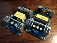
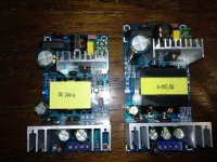
I'm going to be building my bench test gear, dedicate about a 2x5' space in my shop for electronics repair. I have a nice Weller solder/desoldering station, a Fluke 16, some 12v Pb batteries, charger, and a 14v 40A power supply I pulled from a wrecked camper (BTW thats a good way to find some pretty beefy simple on/off PS units for practically no cost). I'm going to set up this area with some switches, relays, etc to minimize clutter for testing and such. Shelving with spare parts and equipment (which I will purchase as the needs come in based on what the amps need for testing). Basically I'll probably need an Oscilloscope and a frequency generator more than likely. I used to do this out of piles, boxes, baggies, and tool boxes... but now I want to do this with active shelving, parts organization (Or perhaps parts via JIT from places like Mouser etc).

Does anyone have a recommendation for hobbyist setups?

What causes BJT based amplifier distortion?

The obvious answer is active device non-linearity, but this is too generic and abstruct. BJTs have an exponential input characteristic, which means, the more current passes through the base, the easier it is to pass more. The output characteristic, that is, the collector current at a constant base current, is not a horizontal line. It is neither a line with a positive gradient, but a curve albeit with small positive gradients. As if these imperfections were not enough, there is also a voltage dependent capacitance formed by both depletion layers at the emitter-base interface and at the base-collector interface. Since, a transistor silicon chip is thin, the emitter-base depletion layer and the base-collector depletion layers are in close proximity, and the electric field at the latter affects the electric field at the former. All these unwanted characteristics of NPN and PNP doped silicon crystals contribute to a transistor operation that is not simply linear, but depends on device voltages and applied frequencies.

Since, this forum is intended for enthusiasts to build their own amplifiers, I would like those who have primarily the understanding of the concepts to comment. The question is how does amplifier topology circumvent these unwanted transistor properties? I would like the discussion to first consider simple three stage amplifiers, differential inputs, VAS and the power stage including its driver.

Please note, I am not asking to repair my amplifier. That, thanks to this forum, specifically, Mooly and mjona and other contributors, still works and is daily filling my home with beautiful music.

GU-17 8wpc push pull transformer input

Wanted to share this project I designed and built about a year ago.

I wanted to use the GU-17 a very cool tube. It’s the size of a el84 but has two plates and 2 control grids. It’s has only a single cathode and screen grid however.

This means a pentode push pull output stage can be designed with a single bottle. This little guy can make a pretty easy 8w maybe even 10w if pushed hard.

I also used a input transformer on this design. It’s not performing phase splitting duty this time though. Only voltage gain and loading the feedback network.

The driver and phase splitter is a LTP using a 6H8C dual triode.

For the power supply I used a capacitance multiplier for B+ and a simple regulator for the screen supply.

The output transformers I used are vintage units out of a GE receiver. They measure very well.

I’ve included the circuit and the PS as well as some FR/distortion/noise sweeps at 1,6&8w.

This amp also has clip indicating LEDs in the screen circuit. Very interesting to see how loud the amp will play before those light.

Attachments

  • 310A2FA1-5E27-4550-9A7C-8BBA1FE159B9.jpg
    310A2FA1-5E27-4550-9A7C-8BBA1FE159B9.jpg
    537.3 KB · Views: 213
  • B9E64965-6C1A-4036-8D89-746E56361A0B.jpg
    B9E64965-6C1A-4036-8D89-746E56361A0B.jpg
    584.6 KB · Views: 290
  • 7E86D8E8-3C51-4EC7-9872-E48200E25C20.jpeg
    7E86D8E8-3C51-4EC7-9872-E48200E25C20.jpeg
    152.5 KB · Views: 356
  • DC3DF164-B33E-4EAD-B046-1DA2E2E0CC56.jpeg
    DC3DF164-B33E-4EAD-B046-1DA2E2E0CC56.jpeg
    131.5 KB · Views: 323
  • 9A91434B-1598-464C-AF00-092006B44F17.jpg
    9A91434B-1598-464C-AF00-092006B44F17.jpg
    767.9 KB · Views: 238
  • 28D74164-8D17-4F79-AA72-8314C0691565.jpg
    28D74164-8D17-4F79-AA72-8314C0691565.jpg
    658 KB · Views: 181
  • C3A679A6-4FC1-4484-9467-18A86989827D.jpg
    C3A679A6-4FC1-4484-9467-18A86989827D.jpg
    1,004.6 KB · Views: 185
  • 234D2046-59CC-4EB8-A02C-11257146584F.jpeg
    234D2046-59CC-4EB8-A02C-11257146584F.jpeg
    627.2 KB · Views: 168
  • CDE90B8A-C19B-4F96-9374-5DA0D2900C75.jpeg
    CDE90B8A-C19B-4F96-9374-5DA0D2900C75.jpeg
    687.5 KB · Views: 145
  • FACE59BD-8889-40CF-B778-A922A5376DDC.jpeg
    FACE59BD-8889-40CF-B778-A922A5376DDC.jpeg
    697.5 KB · Views: 152
  • Like
Reactions: ziffel

Problem with my audio amplifier

Hello, I recently designed a power amplifier with capabilities of around 120W. The problem came as I connected the speakers and turned it on. What happened was the speaker started moving and making noise without any input signal. I also measured the voltege between speaker terminals and my multimeter showed the same voltage that was on the positive output of the power supply, sience Im using dual polarity type psu.

I hope someone here has some insight on the topic, it would be really helpful.

agdr Audio sales thread

I'm collecting the sales information for my various posted projects here, going forward. 🙂 This is mainly so folks can buy bare PC boards to DIY if you don't want to lay one out yourself and have it fabricated. The schematic, BOM, and layout of my boards are all posted at the project links below, along with build instructions for each project.

If you need a board, or want to buy an assembled unit, please visit my website: http://www.agdraudio.com/ .

Happy DIY'ing! 🙂

-agdr


OPA1688 Super CMOY project, with the TPS3701DDCT comparator (DIP-6) adapter PC board

Project thread: http://www.diyaudio.com/forums/head...y-2x-9v-real-ground-headphone-relay-pcbs.html


******************************************************

Inverting Version Of The NwAvGuy O2 Headphone Amplifier project

Project thread: http://www.diyaudio.com/forums/head...avguy-o2-headphone-amp-vs-original-thd-n.html


******************************************************

O2 Booster Board project

Project thread: http://www.diyaudio.com/forums/headphone-systems/244473-o2-headamp-output-booster-pcb.html


******************************************************

O2 Desktop Amplifier

Project thread: http://www.diyaudio.com/forums/headphone-systems/229934-version-o2-desktop-amp-oda.html


NAD C352 not turning on

Hello!
I recently got a non-functional NAD C352, and I plan to use it as a project to get better at electronics and amps.

When turned on, the orange light turns on, but it never turns green. If I’ve understood it correctly, it can’t get out of protection mode(?). I’ve fiddled around with the amp for several hours, but don’t know where to go next. Do any of you wonderful people know where to look? Are there for instance any specific capacitors I can check out which usually causes this problem?

All help is appreciated.

USB - I2S interface for output and input

Hello,
I want to build my own USB soundcard for Windows 10 with at least 384kHz/32 bit DAC, like PCM5102 or similar, and for at least 192kHz/24 bit ADC.

Now I have XMOS interface, which only supports output. I like XMOS, it sounds good, it has no noise, it works well with Windows 10, which I am using. But the problem is, that it has no input.

I have module with WM8782 ADC, which is 192kHz/24 bit ADC with I2S output. I don't know how to connect it to my computer. I was searching, I found interface CM6631, but I didn't found any module, which has wired input interface. Only output one. I also found that some guys overclocked it's output to 384kHz/32 bit, but I didn't found any modules or projects, that uses input and output interface. Do you know any? How can I use CM6631 as input?

Second chip I found is CM6635, which supports I2S input and output at 768kHz/32 bit, but I didn't found any datasheet or projects with it. Do you have any informations about this chip?

Thanks.

Group buy filament regulator for DHT tubes

I have developed a regulator for directly heated tubes that is capable of 1.5A continuous output current. The topology is that of a voltage controlled current source that is high impedance for all but the lowest frequency's of the audio band.


It has a tracking pre-regulator in the negative return consisting of a LM337, this is connected to an adjustable shunt reference and keeps the voltage over the output transistor of the constant current source at a constant voltage.


See the attached images of my prototype, it works flawlessly. The heatsink is a
RAD-A5723/50 STONECOLD AVAILABLE FROM TME.EU


Specs are as follows:


Dropout voltage : 4V worst case scenario
Output voltage : Adjustable between 2.5 and 7.5V higher is possible
output current : 1.5A continuous, about 2A short circuit

Output noise : hard to measure, its below the noise floor of my instruments. There is some popcorn noise on my scope but its low amplitude.

Input voltage : 6.5-30V with no troubles, if the input electrolytic is rated for 35V


Features: Slow start of filaments, thermal overload protection and short circuit proof on a sizeable heat sink up to 7.5V output voltage. The Current source is hard limited to 2A of output current, and the 337 will also limit the current at about the same voltage.


Drawbacks: Higher input-output voltage than some other regulator designs due to the addition of a tracking pre-regulator, you lose about 2V extra due to this addition. But this also means that the LM337 soaks up most of the dissipation at higher input voltages. And gives the benefit of the LM337 internal protection circuitry.


Parts kit contend.

the parts kit will consist of a green ENIG-ROHS board and all the parts pictured on the prototype except the heatsink and m3 stand-offs and to220 thermal silpad. The schematic will be included. And you just have to solder everything yourself. Its all through hole with generous pads so it shouldnt be a problem for anyone who has ever held a soldering iron. One note: the resistors will all be in the same bag so you need a ohms meter or be able to read the color codes for assembly.


price

the cost of one parts kit for one module will be €15. Shipping at current postage rates through POSTNL or DHL whichever is cheapest.


Currently taking firm orders with no down payment, for any questions please ask them here and i will answer them when i have the time.

Attachments

  • photo_2020-10-27_10-19-03.jpg
    photo_2020-10-27_10-19-03.jpg
    168.8 KB · Views: 505
  • photo_2020-10-27_10-19-21.jpg
    photo_2020-10-27_10-19-21.jpg
    154.1 KB · Views: 506
  • photo_2020-10-27_10-19-25.jpg
    photo_2020-10-27_10-19-25.jpg
    243.8 KB · Views: 500

Cyrus 8 Power input sensitivity

Hi,

in these days I'm enjoying my 8 Power Cyrus. Great sound, I love this amp so much

Nevertheless, a small problem. I drive it using one of my vintage preamps: a Meridian 101, a Hafler DH-101 and a Quad 33. With any of those sources, the Cyrus' input sensitivity is quite high, so I'm forced to use only a small portion of the volume potentiometer. Nothing serious, but annoying a bit

I've opened the Cyrus cover, and I've seen several links on the board, some with a jumper installed. I am wondering if any of those is intended to set the input sensitivity

Anyone knows something more?

Thanks a lot for the attention, Paolo

Gutted Golden Tube SE-40 (looking for suggestions)

I have a gutted but good transformers GT SE-40. The outputs are 1.9K and good for around 40W even though I think that’s optimistic. They have a cathode feedback winding off the secondaries as well as a UL Tap. The B+ is around 475-495V.

I’m soliciting for ideas for finals in a project using sweeps, or something different. I know I can use a pair of KT88 or three EL34, 6L6 per channel, but I’d rather have some fun.

Maybe three 6AV5 in UL per channel?

Thanks for any suggestions and I’m not picky about filament voltage. I can swap out the filament transformer.

Woo Audio WA 2 humming/buzzing at loud volume!

Hello

I just bought woo Audio wa 2 and its new, but I'm now experiencing hum/buz when my volume is at clock 11 or higher, my sources are A&K KANN ALPHA and Burson Conductor C3 ref, I have noticed when using KANN ALPHA the Buzz is less noticiable than when using BURSON C3 REF.

any idea what's wrong with my setup, is something to do with the grounding?

I also tried with 2 pins power plug but noise is same and when I touch the WOO WA 2s Chassis I can feel the current I'm assuming the W2 is not properly grounded?

Also whe not using any inputs the Buzz/Hum is almost gone.

Should I buy isolation transformer? Will it help?

Excursion HXA5k, soundmagus X3500 output driver board capacitor value

Hi guys,

2 questions:
- Does anybody know the capacitor value from the photo?

- Both output driver boards work on one side of the amplifier (creates a PWM), but when plugging them into the other side of the amplifier they does not create an output PWM.

6n137 optocoupler replaced, driver transistors replaced. All resistors read the correct value.
INPUT pins of the driver boards has the correct GND, VCC, PS PWM and output PWM.

Attachments

  • 16140774274136738668339584858782.jpg
    16140774274136738668339584858782.jpg
    418.4 KB · Views: 59
  • 16140774897078657177241982947833.jpg
    16140774897078657177241982947833.jpg
    468.3 KB · Views: 59
Projects by fanatics, for fanatics
Get answers and advice for everyone wanting to learn the art of audio.
Join the Community
507,772
Members
7,887,869
Messages

Filter

Forum Statistics

Threads
406,201
Messages
7,887,869
Members
507,772
Latest member
Hypertone