ARC SP8 PSU upgrade

Hi,

I have recently purchased an ARC SP8 Rev 3 from the '83 in working condition that I Would like to upgrade with some modern parts and ideas. I have already recapped the preamp PSU, upgraded 2 OPAMPS, changed the rectifier diodes and put new valves on it, I first Would like to concentrate on the PSU. Voltage references based on noisy zener diodes is my next step. I Would appreciate it very much to have some feedback on several points I Would like to share with you.

My strategy is to replace 2 zeners and a LM329 with the attached circuit (vRef):

1. 2 B+ voltages (phono and line) are regulated using 1 12BH7A and 1 ECC83 (this one working at 400 V, far over specs ?!) together with a couple of tl2071 OPAMPS. Both cathodes of the ECC83 are paralleled and biassed with a noisy 10V ZENER. I Would like to replace the ZENER with the low noise referred equivalent. To provide enough current to the voltage reference I plan to get additional 6mA from a 24v available regulator.

2. An additional 24V ZENER is used to power a tl071 OPAMP attached to the base of a darlington set acting as a HT voltage regulator. I believe the circuit proposed above can provide lower noise at the OPAMP power supply.

3. A LM329 is also used as a fixed reference of an inverting tl071 input. It is a nice device but also a bit noisy.

I Would appreciate your comments / suggestions.

Kind regards

Toni
Barcelona

Audiolab 8000X7

I have been tasked with the repair of one of these lummoxes.
Principal symptom - gradual loss of positive going swing on L channel as
it heated up. Found that some of swing returned if I cooled the + side predriver
(MPSA92) so I replaced it, and the adjacent current sources (BC556x2) This
helped a lot but when I gave L and R a good roasting, found the same fault
appearing on the R channel. Transistor replacement did not help. I'm beginning
to suspect some deeper systematic issue. Audiolab could(would?) not help and
referred me to a service dept in Germany (I'm in New Zealand!). Does anyone
know of any "known issues" with these amps?.
Cheers, M.

Fixed bias vs. auto bias

iam sure this question has come up before or is even unanswerable but i will ask regardless.

Iam planning to build a kt88 amp, i found the circuit for the modified williamson circuit on the Plitron website. A friend mentioned to me that fixed bias was for guitar amps and i should convert to auto bias. Should i keep the fixed bias or convert it back to the williamson? Your thoughts, opinions and past experiance would be greatly appreicated.

Lab 15 design suggestions for HT use?

Hello,

I have a Lab 15 just waiting to be put into use in my HT. I have played around with designing an enclosure for it. But until now I didn't have an amp. Now I have a TA3020 amp and SMPS800RE on their way to me. This should be plenty of power for the sub.

Design goals:
For use in a home theater, so the lower this can go the better.
I am looking to keep this around 5 cf. (6 cf max.)

I am looking a making a TL with a response down to 20 Hz. Total size is ~5 cf.
A br including the port models about the same size and fr.

I am looking for anyone that has experience with TL or tapped horns for home theater. In searching the forum I found a some people using these for pro audio use. But not much info on HT.

Later tonight I will try to post measured T/S and box sims.

Driver Design

Hi All, this is my first post. I am attempting to design a speaker and I have some questions. I have searched the Internet and have not been able to find adequate answers.

The first question is in regards to the voice coil. In order for me to get a comparable Mms to stock speakers I need to use a thin wire (36 awg) to obtain a value of 6 ohms Re. This wire gauge is rated for only 0.21 amps, yet the stock speakers are rated at rms power values reflecting currents ten times this value. Am I correct in assuming that because a music signal is so dynamic one does not consider the rated rms current of the wire? If this is the case just how does one determine if the wire gauge is adequate for the application?

My second question is in regards to the suspension of the diaphragm assembly. Other than centring the voice coil in the gap, are the any intrinsic benefits to a spider? Are there alternatives to a spider?

Lastly, the only information I have found technical enough to design from are the two papers “Green Speaker Design” published by KLIPPEL GmbH. Are there any other good design guides out there?

Thanks

Dynaudio D76 AF - New - NOS - pair in prig boxes

Selling a pair of Dynaudio D-76AF dome midranges.

They are new - NOS, never used. In original boxes.

They were part of a Dynaudio Xennon-3 speaker kit project that was started, but never finished. A friend of friend purchased Dynaudio raw drivers and Xennon cabinets to build these and never finished as he passed away.

This pair was never mounted and originally purchased as spares to another set of D76 that were mounted in cabinets.

I measured DC resistance of each with Fluke DVM. Each measure 5.2 ohms. I also briefly applied low level music to verify proper sound and no distortion. Both sounded fine.

Just as an FYI, I also have the 24W100 woofers and D-28 AF tweeters. These are new - NOS in orig boxes as well.

Asking $425 OBO. Selling as a pair. Prefer to sell here instead of that auction site.

Will post pictures in the next day or so. Or message me and I can email some..

Willing to sell the cabinets as well, but I won't ship those. Need to pick up in the mid-atlantic area (Baltimore - Wash-DC). Willing to drive part way if you want to buy the cabinets.

thanks.

Attachments

  • Xennon3-a.jpg
    Xennon3-a.jpg
    156 KB · Views: 298
  • IMG_1380.jpg
    IMG_1380.jpg
    799.9 KB · Views: 231

Lowrey MX-1 Organ Parts wanted

Hello
At present, I am restoring Lowrey's Orchestration Plus Project, and I am looking for Second Hand Lowrey MX-1 Organ Parts.
I am particularly interested in the CPU Board, the Memory Board, the Parallel Interface Board, and the Orchestration Plus Boards.
If Anyone can help, I am quite willing to send them the proper Antistatic Packing Materials to safeguard the assemblies during shipping/transport.
Thanks, and Kindest Regards;
Telnet100

A New Take on the Classic Pass Labs D1 with an ESS Dac

A new run of these boards is now available! Please see the following thread for details:

http://www.diyaudio.com/forums/soli...ble-here-bal-bal-se-se-lpuhp.html#post3516741


Hi Guys,

After having messed around for quite a while with several variations of Nelson's D1 with various modern DACs, I've finally come up with one that I think is worthy of being posted for everyone to use.

I've combined the excellent transconductance of a power mosfet, with the low distortion of a JFET buffer to get to the circuit below. It's basically a low impedance D1, with a different mosfet, and a B1 buffer in place of the old mosfet based buffer. You could probably call it a D1B1.

The circuit below provides about 2 VRMS at 0dBFS output when used with a ES9006 run in stereo mode. Performance is superb, and all the measurements are attached. THD+N is 0.000515% (-105.5dB) at 1kHz -8dBFS. This is without matched fets, and a seriously kludged home-made PCB, which means it can be made better with a decent implementation. Even the way it is, I think it sounds excellent.

This circuit could easily be adapted to work with any DAC, and provide almost any gain needed. The gain was set so low to minimize voltage swing at the DAC output.

The source of the mosfet sits at 1.65V which is what the DAC wants to see, and the drain sits at a little over 9 volts which allows direct coupling of the B1 input to the drain. Gain can easily be increased by increasing the value of R1, R2, R3, and R4 while maintaining the same ratio.

I'll be starting a PCB layout with this circuit and the ES9018 DAC which should provide some pretty incredible performance.

Anyone feel like helping with the digital side of the DAC?

Cheers,
Owen

Attachments

  • DAC IV.JPG
    DAC IV.JPG
    75.1 KB · Views: 15,397
  • PICTURE.JPG
    PICTURE.JPG
    40.1 KB · Views: 14,657
  • DAC THD+N Ratio.jpg
    DAC THD+N Ratio.jpg
    60.2 KB · Views: 13,838
  • DAC DPR.jpg
    DAC DPR.jpg
    58.2 KB · Views: 12,944
  • DAC SNR.jpg
    DAC SNR.jpg
    47.9 KB · Views: 12,709

NAIS Relays - DS-2E-M-DC12V-1C

i have one packed with 50 NAIS relays - DS-2E-M-DC12V-1C / AG 205344B99 (silver (Ag) with gold plating) for sale. High sensitivity: 200mW input power Type DIP-1C can be used with a 14-pin IC socket. Only complete packed is for sales. Relays were still made in Japan. Asking 100€ + Shipping + PayPal + 4% fee. I still have 2 packs more of these Nais relays, all of which were bought from Arrow / Spoerle Electronic in Germany. Shipping only with registered mail by DHL from Germany. Shipping prices are different depends on the country.

Attachments

  • IMG_20210301_124834.jpg
    IMG_20210301_124834.jpg
    407.7 KB · Views: 92
  • IMG_20210301_124839.jpg
    IMG_20210301_124839.jpg
    376.8 KB · Views: 89
  • IMG_20210301_124918.jpg
    IMG_20210301_124918.jpg
    224.8 KB · Views: 88
  • IMG_20210301_125011.jpg
    IMG_20210301_125011.jpg
    367.8 KB · Views: 86
  • IMG_20210301_125025.jpg
    IMG_20210301_125025.jpg
    257.6 KB · Views: 89

Alternatives to the 2SK2700

I'm interested in putting together a powerdrive circuit for an 845 amp that I've got built. I'd like to replace the fairly tame class A1 capable driver stage that I'm currently using.

I've discovered though, a lack of 2SK2700 mosfets.. I could order on ebay, but I kind of hate ordering stuff from China.

Are there any other compatible mosfets out there that would be suitable for the powerdrive as implemented on this page 845 SE | Tubelab ?

I've been searching online to find equivalent mosfets, and I'm coming up with stuff that is severely lacking in many of the specs I've found for the 2SK2700.

One suggestion was the STP3NK90ZFP.. But it's got a much lower power dissipation rating, and much higher drain-source resistance..
In trying to match up specs on Mouser's website, I've found parts like the Cree C3M0065090D http://mouser.com/ProductDetail/Cre...fT7raD8v7sJKQWPXTvN7IFrDEDiDpnHams%2bSBZJ8w==, but rds-on is higher 90mOhm, power dissipation is lower @ 125W, but continuous drain current is MUCH higher though 36A..

Or the Fairchild FQA11N90_F109 http://mouser.com/ProductDetail/Fai...=sGAEpiMZZMshyDBzk1/Wi2h9uecfVnmSNyG138FKIdM=.. Which looks somewhat similar, although higher rds-on..

What are the important specs with regard to the powerdrive circuit as implemented in the 845SE tubelab page.

Any suggestions?

Crown I-tech repair advice

Hi guys,

I'm writing here hoping that someone found the same behavior or can give me any advice to repair a Crown I-tech 6000 amplifier.

The amplifier came to me not turning on at all. Power diode D1005 from BCA output stage was shorted. I replaced the bad one and the one that is in parallel. After some preliminary tests everything looked OK with one exception. The repaired channel (CH1) is overheating and in ~ 2 minutes it reach over-temperature and is shut down. I must stress out that it passes clean audio until it is cut down by overtemp protection. Cooling system is ok and is throttled progressively to max speed.

First thing to do was to adjust overlap/underlap according to service manual. No improvement. After that I swapped the front-end PCBs between channels and the problem moved on CH2. I made a lot of measurements with oscilloscope and compared with the working channel but nothing came out. Feedback, differential drive to gate drive boards, VP/VN voltage was measured and everything looks ok. Also each component ohmic resistance from bad front-end was compared to the same component on working front-end and nothing. I have no idea what can cause excessive heat dissipation in this BCA topology.

Now I'm out of ideas and ask for diyaudio community help.

If someone needs the full service manual please write me a private message.

Vifa SS D75MX-41-08 FR info + 4 way design critique

Does anyone have a FR plot of the 3" Vifa Scan Speak dome with an appropriately sized rear chamber on it? All of the published graphs are without a chamber and that doesn't show the full low end rolloff potential to incorporate into the xover design.

I'm planning a 4 way mid field monitor build with these drivers.

Woofer - SB 34NRXL75 up to 200 Hz
Low mid - B&C 8NDL51 200 to 900 Hz
Midrange - Vifa D75MX41 900 to 3500 Hz
Tweeter - Seas T35C002 3500 Hz and up

The crossover planned is fully passive 2nd order LR slopes (if i can get away with it) and the option of biamping LF section separately from the low mid with either passive or active filtering. I could have built a 3 way with a better mid driver, but I need 110dB capability (mostly for tracking drums) with low total HD across the whole bandwidth and the D75 mid dome won't cope with sub 900 Hz xover and still play loud enough due to limited xmax.

I didn't have access to the Volt 752 dome or better yet the big ATC, both of which would have been my first and second choices. I've heard the 3 inch Vifa SS dome in other designs and like it alot if run above 900 - 1000 Hz. It can play very loud and clean as long as its not pushed too low. I have 2 pairs of them in case I decide to do a 2.5 way MTM to get more low end and help with BSC while trying to keep up with the midbass section. I'm aiming for -6 dB power response from 100 Hz - 10 kHz which sounds the most natural to my ears.

The tweeter choice was after hearing the shear dynamic capability and low HD of the large T35 Seas dome, even without a waveguide (which I still may use). It has ample HF extension on its own, especially with some passive filtering EQ tricks and it will live a long life crossed over at 3.5k 2nd order LR. I really love the way these large domes sound in general. Im not a fan of most cone mid drivers mainly due to HF cone break up plus the way they beam at higher frequencies. That doesn't mix well with the driver it needs to mate up with and hurts power response as well. I was tempted by the big Beyma TPL150, but it sounds too aggressive in the lower mids to my ears, plus the limited vertical dispersion kills it for me.

Im open to suggestions. If anyone has some constructive input I'd really welcome it.

Modeling of a ML tapered line

Guys,

I am trying to diagnose a loudspeaker that I bought as a kit. I believe there may be an issue with the engineering of the bass unit. The woofer has been fitted in a more or less standard cabinet (for that supplier) and does not sound right to me.

I have spent vast amounts of time reading up. I have found many references to the work of Martin King, George Ausperger, Bob Brines etc. Unfortunately the alignment tables, worksheets etc. mentioned can be found nowhere, and now I am stuck.

I hope that someone could point me in the right direction. If the documents are free for sharing, I hope that someone is willing to do so.

I am a practical guy looking for a solution. I am willing to share the details of the design (drawing of box) and woofer. Maybe someone is willing to help?

I have measured the line length, SI and SO and the terminus size.

4 way design

Putting together a 4 way design using SB acoustics SB34NRX75-6 12" woofers, thinking of using an SB17NRXC35-8-UC uncoated mid woofer AND a Silver Flute W17RC38-08 to handle the upper bass region.
A pair of Morel CAM 558 2-1/8" Soft Dome Midranges and a pair of Dayton RS28F-4 1-1/8" Silk Dome Tweeters.

Have the woofers in cabinets, plan on ordering mid woofers next week.
My thinking on using two different mid woofers is to smooth out any resonances or nuances.
Any thoughts?

YAPLA - Yet Another Peerless Line Array

And so it begins...(?)

For quite a while I've been reading through the various threads on the DIY line arrays based around the the original IDS-25s (Wesayso, Fluid, AttilaM, et. al.) . After giving it a lot of thought and working through some numbers I decided there was no more standing around on the sidelines - time to get in the game. 😀

As a bit of a Xmas present to myself I just put in my order with Madisound for a whole bunch of TC9FD18's. Price was $7.85 USD each for quantity>=45 with free shipping. As much as I was hesitant about line arrays due to the total driver cost, when I started putting together the full build sheet I came to realize that the other expenses, coupled with time and effort needed made the issue of driver cost relatively minor (or at least more palatable) in the grand scheme of things.

Got a cabinet design laid out on paper. The plan is to keep it relatively straightforward - a dampened plywood box, plenty of bracing, front-mounted drivers on a single layer baffle. About 2.2L per driver stuffed.

We'll see if this plan survives first contact with the table saw. 🙂

I'll try and keep this thread updated as things progress At this point I don't expect much construction to happen until the week before New Years.

-b

Crossover software with low latency and presets

Hello all-

I'm hoping to find a PCXO solution that has the following features-

-Presets changeable via key command (I'd like to use an Elgato Stream deck)

-mutes outputs during preset change (presets will get changed with music playing)

-ASIO support or other low latency audio driver option. I think WASAPI should work (I'm not familiar with it), but ideally I'm trying to get my full latency on an IIR preset down to sub 1ms.

A little background, this is for a recording studio with multiple users. I can get a KVM switch for troubleshooting, but ideally the PCXO will be run with no mouse or keyboard. Being able to use the Stream Deck (or similar) then is important because it creates a simple interface that anyone can understand, and limits access to someone messing with the routing etc.

Worse case I can use a daw with assignable midi mapping, like Studio One. But it seems that a dedicated solution might be less messy.

Thanks!

Morel MDT30 v Morel ET338

For quite a while my speaker design was settled. It's three way with a sub; main speakers being SEAS L18, Morel EM1308 and Morel MDT30. I won't bore you with the xover details but the sound was seamless from top to bottom, plenty of depth and ambience and a wonderfully natural timbre - especially piano and acoustic guitar. Jazz made you feel like the performers were in the room with you. Very inviting and enjoyable.

So about 15 months ago I decided on an upgrade. The MDT30s were about 20 years old and probably past their best, so I replaced them with new ET338s. Changed the capacitors from Ansar Supersound to Jantzen Silver z-cap and the resistors from Jantzen superes to Mundorf Supremes.

I can't tell you how disappointed I was with the sound. That ability to put performers in the room was diminished, piano sounded dull and rounded and acoustic guitar just sounded wrong. The sound as a whole was a bit light and 'weak', lacking body and dynamics. Very polite is a good description.

I've spent hours fiddling with the crossover to try and get back the sound I had. I did improve things but never felt happy. Along with the horrible thought of how much all the new parts cost I was about ready to give up. I even changed the caps back in case it was them, but it made no difference. Last week I came to the horrible conclusion that all else being exhausted, it must be the tweeters. So I decided to go back to the MDT30 and give them a try.

First problem to overcome was the cabinet. The MDT30 faceplate is quite small and no longer fitted the cabinet. Thankfully the faceplates on Morel tweeters have similar fixing holes and I was able to fit the ET338 faceplate to the MDT30 body.

So how did it sound? Firstly a slight negative: the MDT30 isn't as sharp at the very highest frequencies. It's a known MDT30 trait and isn't really problematic unless you are listening for it. But, and here we go, my 'in the room' sound was back, piano was full and resonant and guitars totally natural. Sax comes along with solidness and the ability to convey expression - much the same for vocals. Finally, I am able to relax and listen to music again!

One small added benefit. The MDT30 has an even low frequency roll off, but is a bit ragged. The different profile of the ET338 faceplate cures this though I'm not convinced it alters the sound in any way.

new member from UK

Morning and thanks for letting me join.I am not new to electronics,and loved tinkering for years but i am,i would suggest a novice.
I am currently learning from scratch using 'Al's electronic course on Udemy (not sure if this is known by you guys and if its considered any good).
I am learing just for my own benifit, to eventualy build something, repair items and just do it for fun realy.
I am currently repairing old NAD amps, particularly, 3130,3240pe and 3020 versions
🙂

FIRST WATT F2J build

This weekend I have completed F2J. The sound reminds me of my EL84 with no NFB, but with more details and tighter bass. Really sweet sound, the midrange is magical, female voices are perfectly clear and natural. I tried the amp with Karlsonator, but F2J waits for Alpair 12P in some fancy cabinet 🙂 I also tried with ordinary speakers with XO but as expected the sound was rather dull, too dark.

First Watt F2J with Karlsonator 0.53 3FE25 - YouTube

One problem is that - and it was also the problem in the simulation - that the pot is out of the range, so I can't set a perfect clipping - photo attached. So I think I need to reduce the value of R5 to 1.8k or... increase R4. Also, my JFET has the gate reverse leakage current below 0.3mA (at 25 °C, Vgs=-15V, Id=0), so I am thinking about increasing the value of R6.

Mr. Pass, thank you very much for this amp.

Attachments

  • F2J-blue-01.jpg
    F2J-blue-01.jpg
    62.2 KB · Views: 437
  • F2J-PCBs.jpg
    F2J-PCBs.jpg
    160.1 KB · Views: 393
  • clipping.png
    clipping.png
    45.2 KB · Views: 364
  • left-1W.png
    left-1W.png
    19 KB · Views: 318
  • right-1W.png
    right-1W.png
    18.4 KB · Views: 327
  • left-PCB.png
    left-PCB.png
    34 KB · Views: 181
  • square-wave-10kHz.png
    square-wave-10kHz.png
    36.1 KB · Views: 188
  • square-wave-50kHz.png
    square-wave-50kHz.png
    36.7 KB · Views: 151
  • left-3W.png
    left-3W.png
    19.5 KB · Views: 216
  • F2J-schematics.png
    F2J-schematics.png
    151.1 KB · Views: 376

Driving Tactile Transducer with Class D bass amp?

Guys, I'd like to get a somewhat portable system for driving a pair of Aurasound 50w 4ohm bass shakers, aka tactile transducers. I already have a big, heavy Crown amp but I'd like to go smaller and lighter. Before I waste time and money I'd like to know if a class D bass amp, such as the Trace Elliot Elf, could do the job? I'm wondering just how well it could handle it since the caps aren't that big so repetitive shaker "hits" might not be possible. I don't want cheap Ebay amps. I need something better built, which is why I thought maybe these small class D bass amp heads might do the trick. Any thoughts or suggestions appreciated. Thanks.

NAD 3020 series 20

i recently purchased a nad 3020 series 20 amp that was not working,mainly to see if i can get it going, a good learning tool for me, the problem is i am way confused.The service manual i have for it lists different components than what is installed, actualy they more match the 3020A, but even this isnt totaly acurate, so i am wondering if someone else messed about with it before me, which is very possible i guess.so i am at a loss which service manaual to use.should i totaly believe the original?.The other real issue is the little LED board that is installed.when you look at the parts list it shows for example that D803 should be a diode, but is in fact a 2w-680 ohm resitor, and C807 should be a capacitor, but looks like a diode
the service manual only goes up to C805.see attached.So as you can see i am a bit confused .com.

I have attached photo of the board and the 2 alternative parts lists

Appreciate any help or comments you may have, thanks, paul.

Attachments

Comparing some Class D amps

fbb7afa18865c.jpg


fbbdb8597704d.jpg


Hello.

From several month ago, i have found Class D amp for me.
Finally i arrived journey's goal.

For comparison amps, bought its from Aliexpress and ebay for 3 months,
TPA3116, TDA7498, TPA3255(EVM), TAS5613, STA516B (AB32516).

First time, i bought 3116, 7498. 3116 was just bought, not use.
7498, It's not bad. but, when it's bass sound reached some area,
gave feeling stuffy. maybe it was caused by circuit design and Chinese
electronic parts on PCB.

Then i wanted new 7498 have well designed circuit. But, by seller's problem,
it had to changed to TAS5613. It was better than cheap 7498.
i had used 4 months, But, still not satisfied in detail.

I gathered more information about Class D amps form diyaudio.
Got information 3255, bought it. and same time EVM, too. haha.
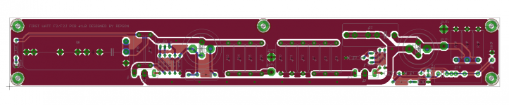
During wait delivery, i saw post mentioned AB32512.
I interested, but, there were 3 models 32512, 32514, 32516.
32512'sound quality was verified many people.
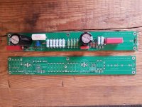
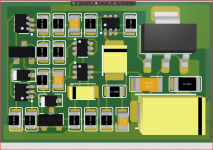
then i wondered how about 32516 in new line up.

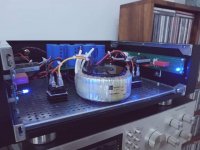
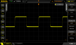
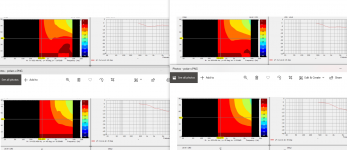
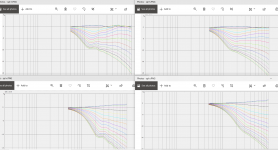
Finally, i had six amps, tested, then concluded 32516 is best in i have.
3255 was good. EVM was better than 3255 from China.
But, 3255's tone was quiet for me. Both were same.

and 32516, it was good. powerful at all range, and detailed.
In long time, i excited first time.

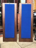
my speaker's output is 100W. any amps can drive it in my small room.
Compared with amps' output, it not large. it couldn't make 32516 warm.
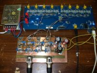
it stayed in cold. same reason, Meanwell 600SE-48 was overpowered.
Too much fan noise, i installed fan controller, then down fan speed to lowest.
But during play music, it stayed in cold, too.

Someone interest to 32516, i recommend smaller power than expected.

Debating a LineArray

Hello, im debating, building a line array. I would like to try a design that has been built and tweaked. I mostly listen to folky male artist Ray LaMontaign, type music.
My room is a dedicated hometheater that sounds great, but i would like more. Im definitely doing two different systems. One audio two channel and my existing 7.1.4 theater.
I like vintage type gear, parasound has some great powerful solid states and theres tons of tube preamps too.
I was looking at the chb-50 build by markaudio just beginning to look around

FS Mundorf AMT 23CM1.1 R tweeters

SOLD Mundorf AMT 23CM1.1 R tweeters

I am selling a pair of Mundorf AMT 23CM1.1 R tweeters . I bought it recently from its first owner because the price was very good. I have decided to sell it because I am not going to use it, I just made some fullrange speakers and I love their sound. Very good aesthetic condition, I do not have a box but it will be packaged well for shipping.
250 € pair, shipping paid by the buyer.


Another hybrid design, this time SE

I've seen this article:
r-tec2102_(07)superT-ULD-amp_KurodaT.pdf - Google Drive

taken from this site:
記事録 2021-2022

and I decided to simulate the circuit at page 109, because I already have a SE pcb that can be modded to adopt that design.

These are the results of the hybrid SE amp with EL84 at 4.3 Wrms:
Code:
Harmonic	Frequency	 Fourier 	Normalized	 Phase  	Normalized
 Number 	  [Hz]   	Component	 Component	[degree]	Phase [deg]
    1   	1.000e+03	8.272e+00	1.000e+00	   -0.52°	    0.00°
    2   	2.000e+03	1.318e-01	1.593e-02	  -90.87°	  -90.35°
    3   	3.000e+03	3.921e-02	4.739e-03	    0.15°	    0.67°
    4   	4.000e+03	1.057e-02	1.278e-03	   89.51°	   90.03°
    5   	5.000e+03	4.913e-03	5.939e-04	 -175.41°	 -174.89°
    6   	6.000e+03	2.385e-03	2.884e-04	  -95.19°	  -94.67°
    7   	7.000e+03	2.314e-03	2.797e-04	    7.19°	    7.71°
    8   	8.000e+03	3.984e-04	4.816e-05	  -95.69°	  -95.17°
    9   	9.000e+03	5.549e-04	6.707e-05	  178.40°	  178.92°
Total Harmonic Distortion: 1.668950%(1.669417%)

Attachments

  • Hybrid-LSK30AY-12AX7-EL84-SE.jpg
    Hybrid-LSK30AY-12AX7-EL84-SE.jpg
    63.3 KB · Views: 446
  • 6bq5_5w_amp.asc
    6bq5_5w_amp.asc
    3 KB · Views: 58

BiB build starting

Hello.... and the urge to build some boxes is upon me. I am a "tube head "---"audio heaven" is low power tubes and back loaded horns..----I have horns (Kirishima /F206 enabled) and a pair of horn shoppe) and a pair of Tekton double impacts gotta keep up with the competition !!!

I have (found) a pair of never used fostex 168ez drivers the BiB on the spreadsheet makes these a good beginner speaker ( learn how not to loose digits and get a positive build experience.....) (Godzilla of course)

looking at the BiB drawings for the double fold no specs but looks to be in the same box size? then I looked at the pic of Mr Cain's proto (the inverted pic) looks like maybe he just expanded the the terminus to scale for a double fold??? am I thinking right here? the longer length would expand the terminus accordingly ? found a pair of 206e's so may try them too ! would love to hear your thoughts
PS have done my own acoustic improvements best dollar return I have ever put into audio!! James

4 khz Visaton crossover wanted

I have a project where I need help calculating a 4 khz crossover.
The configuration is

1 DT 94 8 ohm and
2 W 130 S 8 ohm in parallel.

The volume is 13 liter and I use two BR 6.8 tubes

I know that a 3khz Visaton crossover looks something like this, but the W 130 S sounds very good up to 4khz.

An externally hosted image should be here but it was not working when we last tested it.


What would a 4khz Visaton crossover look like for this configuration ?

EL Jordan JX92S w/ Aurum Cantus G2si ala Jim Griffin w/ Cabinets and Crossover

DIY based on the James R Griffin design. Cabinets are braced 0.75” MDF with a maple veneer that is oxidized to a light neutral gray. Speakers are on spikes.

Two pairs of terminals. Ones on the bottom are to use the Jordan’s full range. The crossover is mounted to the back of the terminal plate for easy tweaking.

These drivers are legendary I just need to make room for other projects.

The veneer got over saturated with the oxidation mix when it was being applied and picked up a minor ripple. Seen in the photos it’s only noticeable up close.

I am happy to answer any other questions.

I am happy to pull the drivers and crossovers and just them or ship the speakers fully built. I can quote shipping, but prefer local pickup in NYC tri-state area for cabinets.

Comment when DM and make me an offer.d

Attachments

  • IMG_0323s.jpg
    IMG_0323s.jpg
    365.4 KB · Views: 201
  • IMG_0324s.jpg
    IMG_0324s.jpg
    304.5 KB · Views: 214
  • IMG_0325s.jpg
    IMG_0325s.jpg
    277 KB · Views: 195
  • IMG_0326s.jpg
    IMG_0326s.jpg
    260.5 KB · Views: 195
  • IMG_0327s.jpg
    IMG_0327s.jpg
    326.9 KB · Views: 191

47uf 450v & 200uf 450v Capacitor for CLC

Hi guys,

I am building a RH84 V2 EL84 valve amp and need to source a 47uf 450v motor run capacitor and a 200uf 450v electrolytic or motor run capacitor for the CLC Power Supply. I am struggling to find a suitable 200uf 450v capacitor. Should I install two 100uf in parallel or is it better to use a single 200uf?

For the 47uf 450v I am thinking of using this Kemet motor run capacitor

C87_series_SPL.jpg


KEMET 46uF Polypropylene Capacitor PP 450V ac ±5% Tolerance C87 Series

RS Stock No. 911-9421 Mfr. Part No. C878BF35460SA0J

KEMET Motor Run Capacitors, C87 Series

C87 Series Polypropylene metallised film with cylindrical aluminium can type filled with resin; faston, plastic deck or cable terminals and overpressure safety device.

Features and Benefits:
High capacitance density
Self-healing metal layer
VDE, CQC and UL810 approved
Rated frequency of 50 Hz and 60 Hz
Safety device protection

C878BF35460SA0J | KEMET 46μF Polypropylene Capacitor PP 450V ac +-5% Tolerance C87 Series | RS Components
It does have 4 tab connections so I am not quite sure how raptors connect it

I have found a CD60 capacitor on Amazon that all look similar made in China with a 5% tolerance. They dont say if they are polypropylene film unlike the one further below which is more expensive.

51j3p-4olsL._AC_SL1024_.jpg


Capacitance: 200uF ±5%
Rated Voltage: AC 250-450V
Rated Frequency: 50/60Hz
Operating Temp. Range: -40℃ ~ +85℃
Size: 10.2x5cm/4.01x1.97"

FATTERYU 250-450V AC 200uF Appliance Motor Start Run Capacitor CD60: Amazon.co.uk: Kitchen & Home

Or this one here which is more expensive and 10% tolerance
Polypropylene Film CD60 Motor Rub Capacitor
51OgzpL32KL._SL1000_.jpg


Product name: CD60 motor start SH capacitor
Rated Capacitance: 200uF
Rated Voltage : 450 V AC(Compatible with AC 250V)
Tolerance: 10 %
Rated Frequency: 50/60 Hz
Size:1.7 x 3.9 inches
Wire Length: 7.8 inches
Color:White
Other: Non polar capacitor, Safe, durable and reliable,Widely used in washing machine/air conditioner/air compressor for better working motor
Package content: 1 x Capacitor

CD60 200uF MFD Polypropylene Film Motor start Capacitor AC 450V/250V VAC Volt 50/60Hz 2 Wire Safe Durable and Reliable: Amazon.co.uk: Business, Industry & Science

Out of these two which is the best to use, or should I go with a well known electrolytic from Vishay, Rubycon or Nichicon ?

Finally, is it worth adding a parallel suitable film cap around 10% of the value on these as well or is that not needed or beneficial in the psu side of things.

Thanks for your help.

Newly built amp hums n hisses

Hi everyone

I just built a small minimalistic ecc82/83 ecc99 combo, but it hums and hisses a lot! Tried a lot of things like elevating the heaters and tried to switch up the preamp heaters.
I have checked all the ground cables, but I still think there is something with the grounding that is of.. if I plug in certain pedals the hum almost goes away!
Anyone have any idea?

Cheers
Gustav

Zener diodes as protection clippers

Someone recently asked how much distortion might be introduced by using a couple of zeners as voltage limiting elements at the output of a preamp. Since this isn't something that can be guessed at from an armchair, everyone went very quiet. I was interested to know the answer, so I did a few measurements using some ordinary 10V and 16V zeners. There's nothing special about the zeners (BZX79Cxx). I just chose them because I had them to hand, and they seemed like suitable values that might be used to protect downstream solid-state equipment.

Here you can see distortion versus level at 1kHz (measurement bandwidth <10Hz-80kHz, 100k load resistance). The rise below 1Vrms is purely noise added by the series resistor. Above this distortion rises, but is lower than most valve distortion up until the clipping point. I was actually surprised at how well the clipping point is defined.
Zener_Clipping1_zps486c8f59.png


Here you can see distortion versus frequency at different signal levels below the clipping point. Offhand I suppose the rise with frequency is due to nonlinear diode capacitance. For signal levels up to 1Vrms the distortion is certainly less than valve distortion.
Above this, distortion at high frequencies could intrude, but since high frequency contect on music typically falls at 40dB/octave above 2kHz, I doubt you would ever hear anything. How often do you send out signals to SS equipment at 5Vrms?
Zener_Clipping2_zpsad21c017.png


Unsurprisingly, for the least distortion, use the highest zener voltage you can get away with, and use the smallest series resistance.

Transistor help needed

I am driving some nixie tubes off of an arduino and some bjts. I am using A5T5058
transistors driven off the Arduino output pins. It works but is kind of dim. Can someone explain to me how to size the base resistors and the resistor on the 170volt supply line? See attached.

Thank you.

Jeff

Attachments

aca v1.8 help

first amp build not going so well...
the led's work.... and that's it.

Ive looked at this for hours and don't see any glaring issues.
anyone see any obvious problems? before i send it out to a pro.

also, any recommendation for service?

ty

Attachments

  • 20210208_171958.jpg
    20210208_171958.jpg
    57.7 KB · Views: 309
  • 20210208_172010.jpg
    20210208_172010.jpg
    70.9 KB · Views: 300
  • 20210208_172025.jpg
    20210208_172025.jpg
    110 KB · Views: 299

Yuichi A-480FL + CD11nd driver

Yuichi Horn 480 finless
Beyma CD-11Nd driver.

CNC machined horn. Ready for sanding and paint or stain.
MDF. Body can still be split in half for easy sandy.

Sold

see attachment for on axis and 30deg
Thanks

Attachments

  • Photo Feb 12, 09 53 04.jpg
    Photo Feb 12, 09 53 04.jpg
    983.4 KB · Views: 285
  • Photo Feb 12, 09 53 08.jpg
    Photo Feb 12, 09 53 08.jpg
    983.2 KB · Views: 266
  • Photo Feb 12, 09 53 41.jpg
    Photo Feb 12, 09 53 41.jpg
    1 MB · Views: 262
  • Photo Feb 12, 10 04 06.jpg
    Photo Feb 12, 10 04 06.jpg
    919.2 KB · Views: 293
  • Untitled.png
    Untitled.png
    12.3 KB · Views: 262

Tantalum capacitors in audio signal path

Hi everyone.

For the last 30 years, I've been using a AVI S2000 HIGH POWER power amp. It has served me very well so far but I think it's time to give it some service and perhaps some upgrades. Besides power supply caps, and based on what I've read, I thought that the two tantalum caps located right after the input signal could be replaced as a sound upgrade. They are 10uf on the + and 100uf on the - both 6v. Given the limited space, what would you suggest ? Since there is a bias trimmer nearby, should there be any adjustments after cap replacement ? Also, any suggestions about other caps replacement. I'm an amateur but very cautious enthusiast and I'd really appreciate your advises. Photos are provided. Thank you.

Attachments

  • 20210225_102153.jpg
    20210225_102153.jpg
    879.7 KB · Views: 634
  • 20210225_103234.jpg
    20210225_103234.jpg
    812.8 KB · Views: 487
  • 20210225_103349.jpg
    20210225_103349.jpg
    607.8 KB · Views: 505
  • 20210225_103734.jpg
    20210225_103734.jpg
    815.6 KB · Views: 471
  • 20210225_102137.jpg
    20210225_102137.jpg
    901.7 KB · Views: 485
  • 20210225_095313.jpg
    20210225_095313.jpg
    997.8 KB · Views: 338

Salas shunt reg for TDA1541A question

I've searched the forum, but I found no info on this (granted I didn't spend hours searching).

I have this (PCB designed by dvb-project) fully populated, except for the current limiting resistors. I left those unpopulated as I don't know what values to use. The LED's are matched and the 2SK170BL's are all matched within 0.01mA(not that it's needed, but I had 16pcs matched within +/-0.01mA).

So, if anyone knows what values to use for the 5W current setting resistors, I'd be grateful if they'd share that information.

Attachments

  • Salas_shunt_TDA1541A.jpg
    Salas_shunt_TDA1541A.jpg
    397.9 KB · Views: 195

Hammond 370BX - winding resistance for rectifier calcs

Does anyone know the primary and secondary winding resistance for a Hammond 370BX (with a 230V primary)? I am trying to work out what would be needed to meet the minimum resistance for a valve rectifier (EZ80, and yes I know it has a 5V winding but I will be using additional filament transformers). I can't spot anything obvious in the datasheets.

Salvaged CD-6 DAC board

Hi all,
I salvaged from a Cambridge CD-6 (brocken transport) a dual TDA1305 balanced DAC board.
Since I cannot find any hi-res image of the schematic, could you help me to find where to connect the input signal? Dac pcb has on-board psu and is very similar to the Dacmagic one.
Here's the only service manual I found:
Cambridge Audio CD6 Compact Disc Player Manual | HiFi Engine

The idea is to connect a Broskie's unbalancer before the opamps...

Cheers,
Vincenzo

Cross-over design software with actual measurements

Hi all, newly signed up but have been reading posts here for years. Many years ago a buddy of mine and I did some work on replacing the crossovers on some speakers of mine and it made such a huge difference. I want to do that again for the recent speakers and wondering what software people would recommend. I see lots of options for cross-over design. But I want to be able to measure the performance of the drivers in the cabinet and use that response curve to simulate the actual final performance of the system/cross-over. We did that before with raising up the speaker up into the air and measuring the frequency response. Our "poor-mans" anechoic chamber.

So there are really two elements I'm looking for, maybe one package can do it all but happy to get separate software if it will work together.

1. Software to measure the response curve of the drivers, I have the mic and audio interface already.
2. Software to design the cross-over that uses the frequency response curve from step one, not a simulation of the driver based on parameters. (Maybe that is standard now?)

Hopefully I didn't miss something but I see lots of software options but really not sure how to compare them to each other.

Thanks

Dynaco PAS 3X - help with an old modification

Hi

I have an old Dynaco PAS-3X I brought some years ago. I think it is time to fix this and get it running again.

When I look at it I do see some old modifications. I have no luck in finding any info about this old mods. Hope someone of you can tell me something about it.

The first mod is on the power supply. The old owner put in an extra electrolytic cap, and also an extra coil. Now the schematic looks like this:
An externally hosted image should be here but it was not working when we last tested it.


Is it OK to have it in this way? Is it good, or should I do anything else? Maybe back to original?


Next old mod is on the PC5 - Line board. Here is a bunch of resistors and caps changed to new valeus. My plan is to change all of the components to better ones, but so far I didn´t notice any mods to the line board, just on the RIAA-board. Does anyone recognize this mod? Should I keep these values or change them back to original?
I DO want to keep the tone controls. Especially while it is a PAS-3X, so I have the possibility to center the tone controls and take them away from the signal path.
Here is a pic whats on the line board in my amp:
An externally hosted image should be here but it was not working when we last tested it.


I also add a picture with the original values:
An externally hosted image should be here but it was not working when we last tested it.


Anything else you may see that is wrong or also is an old mod?


My plan for this PAS is:

- Do the curcioaudio.com mod for the RIAA
- Change volyme-pot to an ALPS
- New electrolytic caps instead of the old ones
- Rewiring the input and maybe change the selector switch (it is in good condition)
- Take away Tapeswitch, Filterswitch and Loudnessswitch from the signal path.


Best regards.
Rampitsch

DIY Tonearm: Double Vertical Spikes - Help Needed

Hey All,


I'm working on a tonearm design which uses a combination of ball bearings for horizontal movement and spikes for vertical. I will share my ideas for feedback soon.

Right now, I need some assistance in sourcing 'spikes' for the vertical bearing. I would like to use something similar to what is used on a Kuzma 4Point tonearm (see below photos). Any ideas?

Having read through existing threads, there are some ideas that might work (football boot spikes for example). However I thought I'd open this one up for any further specific suggestions.

The main criteria from my perspective (in relation to my planned design), is that the spikes need to be small (with a small tip radius) and hard.


Cheers,


Fish


Kuzma Bearing Spikes SMALL.jpg

Base stopper resistors are necessary for output stage emitter followers

Base stopper resistors are necessary for output stage emitter followers, especially in output stages with several complementary emitter followers in parallel. Ideally, an emitter follower should not be driven from a low source impedance without either a ferrite bead or resistor in its base -- or both.

Read the following:

https://www.analog.com/media/en/technical-documentation/application-notes/an47fa.pdf

Attachments

How to filter out radio noise

I've just finished a NE5534 buffer feeding into a couple of NE5532s and everything works as advertised except..when I touch the chassis, I get a sports radio channel through the speakers! The station is well tuned, sounds like AM and comes on and off by touch.

I implemented an input filter before the DC blocking cap with fc=72KHz (1k/2n2 - I ran out of 1nF).

The circuit is fed from single supply 12v. There is 100uF on the rail as well as 100nF directly at pins 4 & 7 of the NE5534 (pins 4 & 8 of each NE5532).

The PCB has a single sided ground plane which is covered by solder mask (but might have incidental contact with the chassis). The input / output / power are attached to a plastic faceplate. The housing is a small Hammond enclosure:

attachment.php


This is the first part of the schematic:

attachment.php


Any suggestions on how to get rid of this radio station?

Attachments

  • 9287825-40.jpg
    9287825-40.jpg
    5.1 KB · Views: 382
  • Front end.png
    Front end.png
    64.9 KB · Views: 414

Magnavox Amp 169 AA schematic

Hi!
Can anyone help with Magnavox Amp 169 AA or Magnavox Amp 169 BB schematic.
Tubes used: 6AN8 (pre and split) - 6V6GT X2 (push-pull output) - 5Y3GT (rectifier)
I've got a Magnavox AMP 169 AA that I am planning to rebuild.
Could only find in poor resolution, many values are unreadable (
Thank in advance !)

Attachments

  • Magnavox Amp 169 AA_Scm_Small.jpg
    Magnavox Amp 169 AA_Scm_Small.jpg
    40.5 KB · Views: 785

DAC as a preamp???

I need a new DAC. I use my computer for volume control, but do not trust it. I want separate volume control. The 90s me would have immediately thought preamp. But since I need a new DAC, my question stands ... DAC as a preamp?
I've posted more info about my system below.
I need some advice on the best way to go about getting volume control for these powerful asp1000 amplifiers. I've read about the high input impedance. I use a computer for my source playing Flac, wav or hi-res audio files. I'm using a very simple dongle Style USB DAC that sounds okay. I have choices, but do not know what my best bet is. For simplicity, it would seem I should just buy a better desktop DAC, such as and SMSL M500 and use the volume control knob on front. Or ANY other DAC with a volume control for that matter. I know I can use my volume control the USB. Provides through the keyboard on my computer. But with amplifiers this powerful, I figure I should have a volume control to prevent issues such as full volume noise blasts, which have happened before when the computer glitches. My second option would be to purchase a regular preamp. This would be the most expensive option, as I would want something at least as good as the Schitt Freya +, and that is $900! I would still need a decent DAC upgrade. This gets expensive with my health issues at hand. The last way I could go, is something like an all tube gain stage. I would still need a DAC, but a simple gain stage kit should only be a few hundred at most. The other two options I can think of, would be the pass B1 buffer clone kit preamp for 150 dollars, but I don't know if it would play nice with a high input impedance of the icepower amp. The most simple and cheapest route, would be be using the Sure digital volume control option. But I do not know how high fidelity that would be. I could really use some help. I've been out of this hobby for about 10 years now. I feel a bit lost and appreciate everyone who has helped so far.
  • Like
Reactions: DblAA

Small Syns 3d replacement waveguide

Small Syns 3d printed replacement waveguide

I thought I would put this here as to not clutter up the main Small Syns thread until they are done.

I am attempting to design a drop in replacement for the horn in the SmallSyns, as it is all but impossible to purchase it now. I'm hoping to just get it close, so no (or a very minor value change) is needed to drop into Bill's design.

The original horn was the SEOS15 sold by DIYSoundGroup, and designed over at AVS Forums by committee. The end product design work was done by jzagaja. Final specs were listed here, but there is a lot of wiggle room there. Later talks put the throat at 16deg with a small conical section before the transition to the OS profile. It reads like this was for the fiberglass horn, so I assume the plastic molded horn used the same profile.

I have never seen an SEOS15, so this should be fun.

I have went through multiple dozens of designs, done in several different ways, and narrowed it down these two to try out. They were designed in two different series, and both are close. These are the targeting shots.

From left to right they are models 15b and 15bb3.

Polars shown with the same layout with Horizontal up top and Vertical on the bottom. No cd throat length added here.
The pink trace is 45deg. 5deg spread from 0deg on up.


Test measurements and explanations starting in post #15

Attachments

  • Capture.PNG
    Capture.PNG
    132.3 KB · Views: 262
  • polar.PNG
    polar.PNG
    231.1 KB · Views: 261
  • SPL.PNG
    SPL.PNG
    332.5 KB · Views: 247

Tone burst as a non-stressful test of maxed output

A software generated tone burst can take the stress out of some types of amplifier testing. An example is when checking loadline performance and operation in to pentode saturation region where continuous tone testing may stress valves and other circuitry.

I was just using REW software's tone burst function to generate 2 full sinewave cycles, along with a digital scope to capture output stage anode voltage and cathode current in a fixed-bias, class AB, pentode push-pull amp of nominal 100W rating. The ears also get it easy if a test speaker is being used instead of a power resistor.

A few different test conditions came to mind during testing.

The amp I had on the bench was a quad 6L6GC, and the 1.7kohm PP output transformer wasn't nicely aligned for such a quad (which would have preferred 2.5k PP from the datasheets for 400V screen and 450V B+). Testing with the output stage overdriven clearly showed max cathode current and min anode voltage to be hitting the pentode curve either over or under the knee when rated or 2x rated secondary loading was applied.

Plots below show orange trace as anode voltage (approx 200V/div), and blue trace is cathode current (100mA/div) for one 6L6GC. Idle condition on LHS of each plot is nearly 500Vdc and 25mA. 0V and 0mA is one division up from bottom. Left plot is for rated 1.7kohm PP of output transformer, and right plot is for 3.4kohm PP (16 and 32 ohm resistive loads on a 16 ohm speaker tap). 2 cycles of 1.5kHz with gross overload of output stage.

V5%2017%20ohm.BMP
V5%2034ohm.BMP


The saturation region performance of each valve in a quad can also be compared by noting the individual max cathode currents. The quad I had was vintage and certainly showed some variation in individual max current levels.

If your scope can present captured waveforms in XY mode, then theoretical loadlines become reality measurements. Plots below are for 1.7kohm PP loading (16 ohm speaker), and the speaker load alters the voltage and current waveforms a bit when the left plot is compared to resistive load plot above. In the XY plot presentation of the same data, the Y-axis is 100mA/div cathode current (blue trace in LHS plot), and X-axis is 200V/div plate voltage (orange trace in LHS plot) but origin (0V) is two divisions from left side.

V5%2016ohm%20speaker%20high%20level.BMP
V5%2016ohm%20speaker%20XY%20high%20level.BMP


Perhaps more for guitar amp applications, capturing grossly overloaded waveforms can be insightful, and a little less stressful than compared to turning up a volume pot and watching a scope waveform for a few seconds and then turning the volume down.

Now I need to think up some test situations where I can get one or both primary half-windings to exceed the normal voltage window limits from 0V to 2x B+, as I'd really like to test the use of MOVs for over-voltage protection across each half-winding of an output transformer.

Ciao, Tim

HH Scott 299C

Decided the best way to have my own 299C was to fab one from the ground up. The PC boards were designed by North Reading Engineering and sourced from US suppliers. Chassis plate is 1/4" Aluminum alloy, CNC machined with brushed finishes.

Haven't decided if selling the amp either as assembled, a kit or partial build but here's the webpage I made for it.

North Reading Engineering

I've got a pair of Lundahl OTs on order for the amp as well and may offer a version using them also.

Some photos:

build2_34.jpg

build2_16.jpg

build2_38.jpg
Projects by fanatics, for fanatics
Get answers and advice for everyone wanting to learn the art of audio.
Join the Community
507,792
Members
7,888,742
Messages

Filter

Forum Statistics

Threads
406,257
Messages
7,888,742
Members
507,792
Latest member
Quentinsommers