Volume control behaviour on Roadstar RCR385.

About the product:
Roadstar RCR385 is a radio cassett recorder with a CD player. The product is from 1994.

i) Since the CD player could not play music CDs, I removed it altogether. Instead, I am using a portable mp3 player.

ii) The volume control started developing issues after about 2 years of use. The multiresistor pot was replaced with another one, but the latter is completely different. The original one was a tailor made component which seems to have been designed to make the product almost useless after about two years of use.

The Issue:
To power the mp3 player, I tried the internal built in power supply, 12V DC, with a linear voltage regulator to reduce the voltage to 3.7V DC, which is required by the mp3 player. This means, the common ground terminal of the radio cassett recorder merget with that of the mp3 player.
Playing audio tracks revealed that when the volume pot is set to minimum, that is, the signal output from the pot is shorted to ground by the volume pot, the actual audio volume does not go down to no-signal and an appreciable loadness is presented to the speakers.

Trying instead, an isolated DC power supply of 3.7V to power the mp3 player does not affect the volume pot with the latter duly presenting no signal when it is set to minimum.
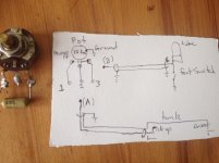
The Question:
Can anyone explain why having a common merged ground, as is common practice in electronics, made the volume pot to fail to reduce the signal to zero (silence)? It seems, with a common ground the audio signal uses another path besides the legitimate one which uses the volume pot to achieve a truly zero signal.

Buzzing hum from Creek 5350se integrated amp

I have a Creek 5350se integrated amp bought new in 2002 and used regularly since. Within 10yrs it developed the intermittent left channel drop-out that's endemic to this amp (crappy ALPS inout switch), and the also-endemic sh!tty static-y feedback through l/r channels when manually turning the volume pot.

I've lived with both problems, on occasion opening the case and applying Deox-it to ALPS switch and volume pot, which seems to alleviate symptoms for up to a year or more. I re-seated the ribbon cable from ALPS inout to main pcb a few years ago - that didn't make any difference pro or con.

Recently a new problem has developed: when amp is powered on an audible buzzing hum issues from about center of amp. Sound seems to get louder the longer the amp is left on, and there may be some correlation between the sound's dB level and ambient room temp (louder when room and hence amp is warmer). At peak loudness I can hear the humming buzz while standing next to amp, ear height about 30" from top of case.

Transformer? Caps failing? Both failing? I'll open the case and inspect but appreciate any comments in meantime. Thanks!

How would you finish this?

More importantly, how should I finish it. I do not have experience sanding back paint all the way to a piano lacquer gloss type finish. I want my cabinets to be all black. I have the cabinet divided 50/50 but not directly down the front panel . Instead I have drawn a 2-inch line down one side which then curves between the woofers in an S and then continues the same two in down the other edge of the speaker front . So it's a dividing line with a dinner plate size curve in the middle one side of the line starts on the right , then curves across the front panel and keeps going down the left. The curve dividing line down the middle is supposed to separate a high gloss black, and a satin black. Wow I could paint it, I have never been able to get perfect results with paint. I was thinking trying to vinyl wrap this, but do not know if those curves on the front panel would create a nightmare to try to get to stay down. Can you please advise me? Thank you very much

Harman Kardon Citation II - rebuild questions

Harman Kardon Citation II - my rebuild thread

Hello audiophiles...

I have a Harman Kardon Citation II amplifier that I wish to rebuild.

A little history: I found it in an estate sale about 12 years ago. At the time I was taking classes in basic electronics, and I had help from an instructor who was very familiar with tubes (WWII radio man). When the bias winding is connected, it hums like a chocolate bunny filled with jumping beans. I managed to limp it into life after replacing the top hat diodes with NTE5814 (overkill I know, I like safe rather than sorry and they fit in the holder nicely) and using a secondary transformer to run the bias but the tubes would always end up glowing hot after about 30 minutes of playing. Between moves, smashing some of the old 12BY7's, it has ended up just being a floor anchor. Now some years later I have a pair of Logan Martins that I'm DYING for this thing to run.

I have been reading THOROUGHLY through the QuadESL and Jim McShane sites, forums, google, etc and I stumbled across Carver's Hotrod edition. That is what I want to build!

So my plan is:
Full rebuild replacing all resistors with modern carbon film resistors, all 5% tolerance. (I notice the Deuce uses a TON of 10% resistors on the schematics)

Recap the entire unit with as much capacitance as I can cram on that board for a reasonable amount of money (10-20% more than the McShane kit, but using more common brand caps)

Fresh tube set - have a matched sextet of 12BY7A RCA black plates ordered already, will order KT120's closer to end of build (the stock 6550's are still testing good and will allow me to test first)

DC restorer circuit, change Bias resistors to bring the tube bias current WAY down, and current inrush limiters to be installed, change transformer taps to take advantage of the extra power available in the KT120's

I am doing this rebuild on an EXTREMELY tight budget, but not so tight that I am willing to skimp on necessary items.

First I'd like to ask anybody thats done a Deuce rebuild or modifications for any advice they would offer someone doing their first rebuild.

Second is I need help with the schematics. I have sifted through the entire internet (see for yourself, The Last Page of the Internet ) and I have found only one schematic that is supposedly the key to the KT120 upgrade. If Bob Carver is listening (or anyone that knows), is this all that needs to be done for the KT120 upgrade on the Deuce?


Thanks
Caleb

Edited to change the title since this is becoming a documented rebuild

Attachments

  • hk_citation2_mod1-2.jpg
    hk_citation2_mod1-2.jpg
    560.5 KB · Views: 1,460
  • hk_citation2_mod2-2.jpg
    hk_citation2_mod2-2.jpg
    518 KB · Views: 1,314

Differential amplifier understanding

Good evening to everyone.
I started this post because i got some problems in designing my class Class AB amplifier, in particular the differential input stage.
the amplifier is running with a single supply of 50v and therefore the problem i encountered in my input stage:
i tried to understand and look ad other schematics that use the differential input stage with a single supply or at opamps such as lm324 wich on his input has a differential amplifier connected from positive rail to ground.
the problem is that when i use softwares as ltspice or pspice to simulate my circuit everything seems fine , the frequency response and the attenuation of peaks and high frequency oscillation is beautiful.
when it comes to reality when i build my differential input stage such as the schematic 2 things happen.
first of the output of the driver transistor goes to all the way to ground or vcc and this causes my Vas stage to not be centered and claim current trough my upper ccs wich causes the output stage to explode in a loud and visibly spectacular explosion.
on the other hand when i bias the bases of the output transistors by lifting up the ground trough an equal resistor divider the amplifier works fine but the feedback applied by the differential changes from what i calculated using the softwares. i want to really know why because i tryed many many polarizations and configurations but i still get the same problem. i'l post the schematic.
Thanks very much and sorry for my bad english :wave2:
An externally hosted image should be here but it was not working when we last tested it.

add aux out jack to mono circuit

I have a radio/cassette player. It's one of those Thomas Home Collectibles replicas, designed to look like a cylinder phonograph. It's just mono, and more or less junk. But unfortunately, it also happens to be the only functional cassette player in the house, and I can't afford to get another. I have hundreds of cassettes, and would like to transfer some of them to my computer for conversion to mp3. But there is no output jack, so no way to connect it. Everywhere I have searched, all I find is info on how to add aux in, but nothing on how to add aux out. Open to any suggestions. (I'd have enclosed a copy of the schematic, but it's inside the unit, and not accessible right now. Couldn't find a copy online.) I could manage to install an output jack... if I knew what it needs to connect to!😕 Thanks!

Filament supply recommendations

I just finished a tube DAC with 10 tubes, and I'm using a Pete Millett DC filament supply. The DAC calls for 6.3VAC at 3 amps, but can be replaced with DC supply. I'm feeding the Pete Millett supply with 7.5VAC 80VA, and the diodes are getting too hot for my liking. My thermapen, which isn't really meant for hard surfaces, shows about 180-190 F. Within the operating range, but they are heating up the caps nearby.

Are there any other recommended 6.3V supplies? I looked at the TentLabs, but ordering is kinda weird with them.

Pioneer PRS-D2000SPL problem in protect

I have amplifier PIONEER PRS d2000SPL in protection. I found defective driver IC861 (TND505) it's not on sale anywhere, I decided to put tnd506. Put, voltage appeared all. But again triggered protection. Voltage jumps. I disabled the feedback 2 leg protection transition loop but the music has not appeared. Please tell me what can be done?

BLOCK DIAGRAM HERE:
https://drive.google.com/open?id=0Byp6dPywKnEPOWFjMVh6WWRSZFU

Jamo D7 volume control removal

Can anyone give me any advice?

Going to send my Jamo D7 sub off for repair, but the company only need the electronics from it. Everything else came out all ok, but the volume dial seems to be held in place by a circular plastic surround from the inside. I do not want to force anything and end up breaking it, so has anyone ever received it? If so, how?

Lastly, if anyone has by some very slim chance has one of these spare please let me know.

6BQ5, 8BQ5, 10BQ5 amp heaters

About a year ago I got a deal on a case of NOS 8 and 10 volt BQ5 tubes from a local guy in Indiana. So I'm thinking of making the Broski 5 parallel tube SE schematic from back in 1999. Because its parallel tubes I want the heaters in series per channel so they all go out if you pull a tube out. To make the amp able to use 6, 8 or 10 volt tubes I'm thinking of getting an Antek 30 volt transformer and an Antek 10 volt transformer. These have dual secondaries. Five 6 volt tubes in series is approx 30 volts, 8 is 40 and 10 is 50. so the 30 volt transfprmer would be in circuit all the time with the secondaries in parallel. If I install 8 volt tubes then Ill add a 10 volt winding to get 40 volts, If I use 10 volt tubes then Ill add both 10 volt windings to get 50 volts. Then trim the strings with resistors experimentally. I was thinking DC heaters but that has its own set of problems with power loss. (Ill be using a one-Electron OPT UBT-1).

Does this sound like the way you would do a 6, 8 or 10 volt filament option using stock transformers?

Capture.PNG

AS-1230 - 100VA 30V Transformer - AnTek Products Corp

AN-0210 - 25VA 10V Transformer - AnTek Products Corp

Embarking on a massive vintage RCA build

hello all. I'm new here, so I am not sure if this is the best place for this or not. please nudge me elsewhere if appropriate...

I have been collecting old rica preamps, power supplies, and mixers for a little while now, and I am ready to build... something? by the end of it, i am hoping to build a summing console with a pair of ba-23 line amp followers), and a mess of outboard preamps.

I have these things to mess with:

an old mixer carcass (a BC-B3 that has been gutted, except for switches and pots, meter, etc)

1x ba-21 tube preamp
2x ba-23 tube line amps

2x ba-73 preamps with the appropriate power supply (bx-71 maybe?)

3x bn-6b 4 channel germanium mixers (one in perfect working order, 2 others need to be capped and probably a few transistors replaced)

1x bn-16 4 channel mixer (needs caps and such, but has the "ladder" style attenuators)


I have some professional development funds available to me from my school. I would like to find someone whom I can pay to walk me through some of this. I do have pretty extensive soldering skills, and can read schematics fairly well, though I do love a good accompanying diagram...

would anyone here fit this bill? or can anyone nudge me in the right direction?
"cold call" emails to a few places have gone unanswered. I don't blame them - it's a weird cold call!


basically I would want to wire up the console as, well, a sweet summing mixer.
and get the other bn-6b's working. then get the other preamps up and running, and POSSIBLY find a way to put direct outs on the bn-6b's, though I understand the is not practical for the bn-16.


well, I guess that's a hell of a " howdy folks", but " howdy folks"!

REGA RCA INPUT REPLACEMENT

Hope all are well.


Has anyone successfully replaced the RCA inputs on a REGA MIRA 2000 thru MIRA 3 integrated amps?

Most of the RCAs on my Mira 1 have broken loose or missing insulators inside the jack, and I want to replace them. But I have never done something like it, and there is zero info I can find on what kind exactly they are to replace them.


Any ideas or experience?

Much appreciated!

Big Sounding Speaker

Hey there!

Looking to build my first DIY soeaker and have been looking at a few kits, such as the solstice, the Statement II's, the Satori SBA 951, and Troels DTQWTs. I do plan on complementing these with subs and I am going to drive them with some IcePower 1200AS amps.

One thing I was wondering is I have noticed in hi-fi shops, like the wilsons and some of the other big speakers really sound big. I am not sure if it is 100% the room or the speakers themselves. One theory I had is maybe it is related to really good off-axis response. I have some Spendor S8e's now and am looking to get a bigger sound that feels more real and more like a live experience with my new build.

Any advice you have would be appreciated.

6112 and 6111 Mini-preamp

Had a go at designing a basic line level preamp to give me a taste of 'tube' sound with one 6112 front stage and a 6111 as a twin cathode follower, SY will love this.

Could have gotten away with using only one 6111 but decided on two, making the total complement 4 tubes for stereo operation, and seeing as I would like this portable, a 12V gel battery will power the heaters nicely.

Going by the data sheets I think I have everything close to right, although they could be totally wrong, anyone have any suggestions? Open for opinions on the HV supply from 12VDC.... I'm trying to follow the KISS principle on this one, no SS, single end. Nice and simple with reasonable sound......

Sorry about the photo, no scanner at the moment so used my camera...

Cheers 🙂
Minitubepreamp.jpg

Are Mono Blocks worth the effort ?

So I'm gonna build a "high end" amplifier for 2 channel listening.
Solid state with the best components I can get. Most likely a "dual mono "configuration with 2 transformers if it is to be in a single chassis. So the cost difference is in the chassis.
Currently listening to a Pass F5 single chassis that I built a couple of years ago and looking for a "covid" project 😀

When it comes to the chassis, is it worth the effort and extra cost to build Mono Blocks verses a Single channel chassis ?
Even if it's not about the cost are there big advantages to mono's ?

I hear that there is less cross talk and some other small differences but is there some real world gains to be had ?

Adding resistor to 16Ohm speakers when powered by Pass Labs' 30W amp

Accordind to a video by 'Steve Guttenberg Audiophiliac', Nelson suggested putting a 16Ohm resistor with Zu Audio speaker (16Ohm) when driven by First Watt SIT 3. The results were supposedly great.

The Audiophiliac finds bliss with a 30 Watt amp - YouTube

I have a similar situation. My amp is Pass Labs Aleph 3 and my speakers are Rogers LS3/5A 16Ohm. Shall I also put a resistor parrellel to the speaker to reduce the impedance to 8Ohm?

New DIY Amp based on EL503/EL520

Hi!

I know EL503 tubes are quite rare nowadays and maybe it is stupid to base a new project on them. But some years I got some old guitar amps for free, they were named Faylon P200 and they were not really good sounding amps.
But the amount of power (200watts on 4 tubes!) and pretty special specs in the 4 (!) EL503s in the power stage made me interested to test them out in a diy hifi amp.
They seem to be like one of the last new tube designs before solid state took over! EL520 and EL503 seems to be exactly the same thing by the way.

I got two guitar amps working well and sold those, sold another set of 4 EL503s (I got good money for the last 4...) and I’m now left with remnants from two amps, minus one set of tubes. So 4 EL503s, two PTs and two OPT (IIRC 1.7kohm push pull). Stock they were configured as parallel push pull.

I can’t restore another amp, enclosure and all is so rotten and I’ve already brought two back to life. So I would like to design a hifi stereo amp around these four tubes regardless, just for fun/for teaching myself.
I’m learning designing tube stages based on load lines etc, but I am a rookie right now. I have constructed one ef86+el34 se amp and one el84 push pull just from others schematic. This is my first own design. I’ve heard it described as the last evolution of the EL34, which sounds good if there is any truth to that...

I’d like to hear simple SE amp with these, just one per channel. Maybe hard to get suitable OPT for that? If I understand correctly they do seem to be pretty easy to drive. I have two e80cc that i could use as drivers, maybe need more gain?


I was thinking if anyone else have had this idea before and maybe have a schematic or an opinion on whether or not it could make a good amp or not?
All critisisms are welcome!

Data sheet:
https://frank.pocnet.net/sheets/010/e/EL503.pdf

See attached image for schematics of the original guitar amp, notice only one ECC83 for all those power tubes! There is some solid state preamp circuitry before that as well if I remember right.


Best regards,
Lars

Attachments

  • A5C84374-90BB-4C4E-B49D-10DD03C75EBD.jpeg
    A5C84374-90BB-4C4E-B49D-10DD03C75EBD.jpeg
    370 KB · Views: 775

Question about DAC chips

I've been a long-time lurker but just recently made an account. I want to know why doesn't TI start making the PCM1704 chips again? Or Philips with the TDA1541.. Looking at the current demand, they can probably sell a lot of units..

P.S. I'm not an expert in how chip manufacturing works so sorry if my question was bad or I posted this on the wrong section..

DIY Public Service Announcement: Beware Fake Low Noise Regulators

Part Numbers: MIC5219-3.3 MIC5219-5.0 MIC5205-3.3 MIC5205-5.0

This message is intended for those who are not already aware that there are fake low-noise regulators on AliExpress, eBay, etc.


These fake regulators “work” as basic regulators but are not low noise and do not meet the specifications. In other words, cheaper regulators are packaged and labeled to appear as more expensive ultra-low noise models. Since they regulate the voltage most of the users will probably be fooled unless they employ sophisticated tests with an LNA to determine that they are not really the ultra-low noise model they are supposed to be.

In this case they are faking these models of ultra-low noise regulators: MIC5219-3.3 MIC5219-5.0 MIC5205-3.3 MIC5205-5.0.

Since they are faking these less expensive and less known models, I would be shocked if they were not faking the more expensive and better-known low noise regulators that have more demand and higher profit…


The photo shows an example of the fake “MIC5219-3.3” model. A real MIC5219 has a bypass connection to lower the noise. On the fakes there is no connection to the bypass pin. The seller was one of my most reliable online sources. (Reliable based upon extensively testing the products received.)


When these are not fakes they are often used as low noise supplies and references for high performance ADC and DAC such as where they are seen inside the E-MU 1616m and 1820m recording interfaces.

Attachments

  • Open Circuit No Connection To Bypass Pin On Fakes.jpg
    Open Circuit No Connection To Bypass Pin On Fakes.jpg
    376.2 KB · Views: 267
  • Datasheet From Manufacturer.png
    Datasheet From Manufacturer.png
    51.4 KB · Views: 279

my gilmore class A amp

This is a amplifer desined by Kelvin Gilmore in headwize's article. I made it myself last month. It used 2SK170/2SJ74 in place of 2SK389/2SJ109. Sounds very exellent. very comfortable and smooth. more wide more airy. I love it. It's one of the best in my DIY headphone amp collection.^^

Attachments

  • 1.jpg
    1.jpg
    104.8 KB · Views: 1,930
  • 2.jpg
    2.jpg
    104.8 KB · Views: 1,857
  • 3.jpg
    3.jpg
    121.1 KB · Views: 1,821

Cayin 270P left channel dead, -10VDC on output

My 18 years old Cayin 270P power amplifier has stopped working in left channel.

Please see attached schematics (uploaded to this forum by a nice Norwegian back in 2012)

Left Channel :
I can measure -10VDC on the output.
The PSU's are all fine, that is +-70V and +-55V.
On Q209 base is -14VDC, on Q208 base is -10VDC

On the working right channel, the same figures are -1.2VDC and +1.2VDC

Any suggestions would be appreciated.

Best Regards
Poul

Attachments

18'' Rear Loaded Horns designed with HORNRESP - help needed!!

Hi everyone,

As previously said in other posts, I've already designed and built 2 Front Loaded Horns with 15'' drivers which sound great ! Thanks so much David for releasing and always improving HORNRESP.
To pursue my bass quest, I'm planing to build up 4 others bass bins with 18'' drivers but this time with Rear Loaded Horn. The aim is to get proximity response and bass pressure feeling with the direct radiating driver combined with the horn's long range abilities - not looking for a wide range of frequencies as usually in HiFi designs : 35-110Hz should be enough!
Some informations : Drivers are Precision Device PD186 / The design below is for a stack of 4 bins in half space.

First, I'm not sure to use HORNRESP correctly in case of a Rear Loaded Horns... 😕
- regarding the 4 drivers in parallel in hornresp, to get the sensitivity of each box + 6 dB for the full stack, should I fix Eg = 2.83 v or 2.83x4=11.32 v?
In other words Eg=2.83 v gives the sensitivity of the complete stack (4 speakers) or hornresp assume that 2.83 v is provided to each speaker ?
- is a T=0.33 not too small… what are the incidences on the results?
- Vtc/Atc… I chose for Atc, the smallest section crossed by the waves going through the horn (Atc = S1). So that Atc also defines the limit of Vtc (minus the driver volume) - is that right?

About the results :
SPL looks correct to me even if some oscillations of +/-3 dB appears in the frequencies range (assuming that half space calculations is a bit rude). But what about the other results… some interpretations would help me a lot!
- Delta Phase response < 180° but pretty close to boundaries!!
- Group Delay??
- Acoustical Impedance??
- To get the combined response of the direct driver and the horn what length/distance should be enter in hornresp as the Horn Mouth and Driver are in the same plan? L=0m?
- Any other important recommendations?


Many thanks to everyone for this forum and the help provided… 🙂
Oliver

Attachments

  • BBC.RLH118_shape.jpg
    BBC.RLH118_shape.jpg
    28.8 KB · Views: 1,001
  • BBC.RLH118_Hornresp_param.jpg
    BBC.RLH118_Hornresp_param.jpg
    53.5 KB · Views: 1,030
  • BBC.RLH118_Hornresp_SPL.jpg
    BBC.RLH118_Hornresp_SPL.jpg
    112.2 KB · Views: 984
  • BBC.RLH118_Hornresp_phase.jpg
    BBC.RLH118_Hornresp_phase.jpg
    45 KB · Views: 906
  • BBC.RLH118_Hornresp_AcImpedance.jpg
    BBC.RLH118_Hornresp_AcImpedance.jpg
    120.2 KB · Views: 850
  • BBC.RLH118_Hornresp_GpDelay.jpg
    BBC.RLH118_Hornresp_GpDelay.jpg
    38.4 KB · Views: 247
  • BBC.RLH118_Hornresp_Impedance.jpg
    BBC.RLH118_Hornresp_Impedance.jpg
    102.3 KB · Views: 260

THAM12 - a compact 12" TH

Hello all !

For some time now I have been pondering the concept of a 12" TH, I have also noticed several threads poping up regarding 12" TH's, so why not make a contribution ?

A coupple of weeks ago my good friend Johannes Rodin really kicked it off by sending me the spec's for the Beyma 12P80Nd driver, and this driver became the base for the development, but then I realized that it was rather expensive.

The THAM12 is roughly half the size of a THAM15, but it should still provide a good alternative to the other great designs out there, especially if you are after a very compact solution.

Thanks (again) Johannes for providing great ideas and helping out with the balancing of different driver proposals.

This is the THAM12 :

Martinsson's Blog -THAM12

(includes drawings and simulations of numerous drivers)

example with B&C12PS100 in 1PI env. :
THAM12_FINAL_HRSPL1PI_BC_12PS100.jpg


Enjoy! // Martinsson

Current (Apr '21) recommendations for good self-build DAC board or product

Hi all

The number of threads here recommending DAC boards is a bit overwhelming. And when you follow the eBay link it is inevitably dead, even for some quite recent posts.

So I would like to ask the experienced here, which board (in April 2021) is a good choice for a self-build and experimentation project. Of course I would prefer to hear about actual experiences rather than web hearsay etc.

My criteria are:

  • Uses good parts not a risk of fakes or out-of-spec - for the digital chips in particular
  • Is currently available from a reputable seller
  • Has balanced output (either voltage or current but I suspect the latter is more likely)
  • Has a good chance of excellent sound quality with the right attention to power supplies and the audio stages
  • Is not much more than £60 to purchase unless it's really special
  • Has at least SPDIF electrical and USB inputs - optical would be nice too
  • Will manage some of the most recent digital standards and hopefully some of the ones coming along soon too

I am agnostic about R-2R or delta-sigma (or whatever else is out there) and I'm not allergic to good digital filters as they are very effective at what they do if well conceived.

My plan is to focus on good power supplies and particularly the audio output stages. For a current-out DAC I'm going to experiment with a top quality step-up transformer and active transimpedance amps either discrete FETs or fast high spec op amps and passive filtering. If it was possible to have very low or no DC on current outputs that would be great but I'm not sure how likely that is.

I guess a recommendation for a good second-hand commercial unit that has all the right digital parts but where the audio out can be tweaked is also of interest.

Many thanks in advance for all the insights!

Michael

DAC linearity test CD

I am thinking of creating a test CD for checking DAC linearity. It would contain 15 tracks. The first track contains:

0000000000000001 repeated 15 times
0000000000000010 repeated 15 times
0000000000000011 repeated 15 times

That is a "mini-triangle" containing 3 discrete analog levels, something like this:

oooooooo____ooooooooooooo____ooooooooo
oooo____|oooo|____oooo____|oooo|____oooo
____|oooooooooooo|____|oooooooooooo|____

Don't look at the o's, just the bars to imagine the waveform.
45 samples make up about 980 Hz. One step is about 43 uV. I suppose this needs to be further amplified (probably with a simple op-amp gain stage) to be viewable on an oscilloscope. This track will check the 2nd digit. The second step should be exactly between the first and third step.

The second track contains:

0000000000000011 repeated 15 times
0000000000000100 repeated 15 times
0000000000000101 repeated 15 times

That is the 3rd digit is checked for linearity.

With 15 tracks one could check all the bits from LSB+1 to MSB.

What do you think about this idea?

Thoughts on these crazy cheap transmission line cases?

I had never seen this site before today, but I was shopping around for toroidal transformer covers and I came across iwistao.com
They seem to have a lot of cool and inexpensive audio gear.
These speaker cabinets caught my eye. Less than $70, and they seem like they'd be great for a full range or coaxial driver as part of a smaller desktop or nearfield setup.
What do you guys think about these?
speaker_kit_1024x1024.png

0.75" Tweeter - Baffled (pun intended)?

I think I have finally settled on an outline design that seems to suit my requirements and sims well with a 0.75" dome tweeter.

So the question is - It models well with an Hiquphon OW2 (and OW1) but is there a noticeable difference between this and the Scanspeak and Linn equivalents? Supplementary question, is there any difference between the various scanspeak models?

So not sure what the differences are between the following -

OW1 vs OW2 - easy this one - slight increase in sensitivity in the OW2 - match Pairs £300.

D2008/8511(Non-ferro), D2008/8512 (ferro), D2010/8511 (Non-Ferro), D2010/8513 (ferro) - All pretty similar, D2010/8513 seems to be the smoothest with latest breakup (marginally) - £65-75 each

Linn D20-LP1-1 (OW1?) and D20-LP1-2 (OW2?) - can get these second hand around £100 per pair

So what's the difference as many retailers sell them as interchangeable items for Linn/Naim/Proac/Spendor speakers and I can get most to sim OK with my design - are the OW1/2 worth twice the Scanspeak.

I know sound/worth etc. are subjective but would like to hear views on these tweeters.

X-over for SUbwoofer

Hi,

I am not that familiar with x-over filters from Subwoofer, commercial or DIY design. Questions please:

1. What kind of filters do high-quality commercial subwoofer use in their sub, e.g.BW 12db(-3dB at F3) or something else if so what? Please explain.

2. If I build a subwoofer from scratch and use an external DSP filter what kind of filter should I set if my main speakers are sealed? DO I have to phase invert if necessary, how to make sure the phase is correct? BTW I have a measuring instrument, microphone and REW s/w. Please explain.

This would help me to integrate my Sub with the sealed Main speakers.

Thanks to those who can answer my questions?

Omni direction cheat

Hello,
I’ve been taking a long read of the linkwitz lab pages over the last few weeks and started to obsess over whether I can cheaply test out the omni directional approach without a completely new build.

The idea I have settled on is to take my existing diy loudspeaker project (a 2-way JX92S/ XT19 + minidsp) and add a narrow face-plate wide-range driver on top.

The idea is that due to the narrow faceplate, the wide-range driver will be acoustically small over a good part of its range, resulting in diffraction and a spherical radiation pattern.

The minidsp setup will allow me to easily compare different configurations of the 3 drivers.

How would you build 2 amps for a wet/dry setup?

Hi everyone, as the title implies, I'm looking to design a couple amplifiers for a wet/dry rig I want to build. Right now, my plan is to design and build two amps, with each driving one side of a 2x12 stereo speaker cabinet I have. The first amp, I want to be essentially a decent pedal platform with a good clean tone and as much headroom as I can muster. The idea being to have a channel to put all my time-based effects without having too much distortion after them in the chain. The second, I want to have a good crunchy overdrive tone, and have a decent variety of overdrive tones.


Since they're both going to be feeding identical speakers, my plan was to build both with 6v6, push/pull output stages. Right now, my plan was to have the dirty amp something similar to a 6v6 plexi, but with cathode-biased output stage, and for the clean amp, build something with minimal preamp gain using 12at7's.


So does any one have any thoughts? What would you do differently? Is this concept even worth pursuing? Any general advice?


Thanks!

First Watt F4,5,6 or M2 for biamp

I am contemplating biamping my magnepan's mid/tweeter panel.

The F4,5,6 or M2 appear to have sufficient and similar power at 4 ohms, though I'm told there are subtle differences between them.

Is there any particular model that would excel in the mids and tweeters?

Presently, I don't have the time to devote to a build. I've heard that many forum members have legacy amps in their closets, having built many amps over the years and acquired a personal preference or experiencing system compatibility of one design over another.

From. what I understand, Mr Pass does not object to the sale of legacy amps as long as it is not a for profit business. enterprise, and sell them to fund their next First Watt project.

To that extent, if anyone wants to sell their legacy amp to a good home, please PM me. I promise to feed them a lot of signal and exercise them regularly. 😁

Because of shipping costs, I'm confined to amps living east of the Rockies or the West Coast.

OK, criticize my OTL Headphone Amp please

I made this cathode-follower based headphone amp about 20 years ago. It developed a wiring fault that made it so the thing got no power, so it was in for repair. The repair was quick and easy, so I turned my attention to improving the design.

The B+ is 180V, made from full-wave rectifying the 120V secondary of an isolation transformer rated for 0.4A. The higher than expected voltage results from drawing only 170mA or so total plate current through the transformer.

1) I replaced the output cap from 470uF 100V to 100uF 400V. I figured having a 100V rated output cap was just asking for trouble, even though the voltage at the cathodes is about 75V. Still, what is it at power on? Probably up near 200V for a few seconds. Yikes. Now there's no drama.

2) Added opposite-polarity 15V zener diodes across the output, to keep giant voltage spikes from blasting downstream from the outputs. Adding them did not change the sound one bit.

3) To try to keep oscillations in check, I added an 82 ohm build out resistor. Then to keep output impedance down as low as possible, I bypassed the build out resistor with a 91uH choke (it's all I had off the shelf). Adding those didn't seem to change the sound one bit (much to my surprise).

4) The big change was adding 13dB of plate-to-grid negative feedback. By my calculations, three 6DJ8 triodes running as cathode followers with 11mA plate current each should result in about 30mA gm total. That would mean the output impedance would be about 33 ohms. As predicted, this amp sounded awful into 32 or 50 ohm headphones. Weak, like it was wheezing trying to drive them.

13dB NFB should reduce the output impedance from 33 ohms open loop (with no build out resistor) to around 8 ohms. The gain was reduced from 12X open loop to 3X closed loop (as predicted). And, as predicted, the amp is now able to drive 32 ohm headphones to acceptable levels without sounding completely stressed out, and actually sounds quite good driving my pair of Audio Technica ATH-30X headphones (70 ohms DCR). It sounds really good driving my pair of Sennheiser HD650.

5) The heater supplies are stupid, but it seems I got away with it. The amp does not hum, but the heater voltage is a bit low at 5.9V DC. I'm too lazy to try replacing the diode bridges with Schottky diodes. It seems to be OK the way it is.

Attached is a schematic of the amp. Does anyone see any horrible gaffs?
--

Attachments

  • 6DJ8 Headphone Amp - schematic - 2021-04.jpg
    6DJ8 Headphone Amp - schematic - 2021-04.jpg
    164.4 KB · Views: 442

Audio lab equipment help

Hello,

I've been fixing some audio equipment for the last few years and wanted to get a bit more serious about it, so I decided to buy some equipment.
The bare minimum would be a good multimeter and a soldering iron but I want to be able to calibrate a few things if possible (r2r's, compressors, analog crt scopes etc.. ) . My budget for now is around 2k max which I know isn't too much but I hope to make do.
After looking at the options I'm completely lost but have settled on some possibilities.

Keithley 2015 can be found for around 600 bucks and does seem to be worth it for me because of the extra thd functionality.
I'm not really sure though if the thd function is adequate , I think it goes down to 0,001% noise with external generator, but is this enough ?
Other option would be a new 5 1/2 digits dmm around the same price but I would need to find instruments for thd/noise/db measurements.

On the soldering side I can find the jbc cd-1bqe for about 300 euros which seems good. I would love to have a desoldering pump but can't find any station under 1k so that again is not an option .

I already have a ds1054z and for now it serves me fine so not looking to upgrade that right now.
I can see for audio analysis and signal generation a computer with a sound card could be adequate(?) . I have an orion 32 I could use.
Also looking at the de-5000 for my lcr needs.

Is any of this really a good idea ???
Thank you .

Single Ended Screen Drive?

I finished TSE-II 300B Monoblock #2, sounds great as expected, so on to the next Tubelab Project; one of the following:

(1) TSE-II (Stereo) with 2A3s or 45s.
(2) Universal Driver P-P monoblocks with 6L6GC/KT66/KT88
(3) Universal Driver P-P with 6AV5s or 6BQ6GAs; mono or screen drive (?)
(4) TubeLab SSE with 6AV5/6BQ6GA in SCREEN DRIVE

That last one popped into my head because I have a well-abused breadboarded SSE board already equipped with outboard driver sockets.
Plus, several dozen 6AV5s and at least a dozen of 6BQ6s (their top-cap cousin).

Maybe a nice fill-in project...

However, I've NEVER SEEN a single-ended screen-drive, and don't know if it's even POSSIBLE.

With the breadboard SSE, a screen supply is pretty easy.

If Power Drive (with MOSFET) is required, I could just INSERT it in place of the coupling cap; already have a prototype Power Drive board built & tested in my old Point-to-Point TSE clone that I'm not using.

Is SE Screen Drive possible?
Is it worth doing, or should I just work through the UD P-P progression, i.e. 6L6/KTs/Sweep Tubes?

Attachments

  • 6BQ6GA.jpg
    6BQ6GA.jpg
    559.7 KB · Views: 286

How to "add tube sound" to a system

I have finally purchased the components in my system. I went to solid-state again. I am asking what the most simple, yet have a decent way to add tubes to a solid-state system, and Tube roll? I do not know the terminology very well. I don't know if I'm looking for a buffer, or a line stage, or something else. All I'm trying to accomplish is to be able to add tube warmth, and tube roll, without degrading sound quality. Is a small something made that goes between the preamp and amp? Or between the DAC and preamp? Or does a tube product need to be large with a big power supply just to sound decent? I'm not looking for a full size 19 inch component, but something simple if that is made. I did search First, but did not find what I was looking for. Thank you for your help. Oh yeah, I'm running everything balanced XLR

FS: Pass Amplifier F1J Clone for Repair/Parts

SOLD One Channel drifts about 0.6V at the speaker outputs as the amplifier warms up. I was able to identify that one of the SemiSouth E120R100 mosfets was sensitive to temperature changes using a diagnostic “freeze” spray. I am the second owner of this differential F1J amp clone which I purchased as a backup amp several years ago and used it less than 10 hours total. The chassis gets HOT measuring 136F with the top cover off. Aluminum cover is included.
I added large potentiometers to be able to adjust DC offset to the speakers from the back. I have no schematics or diagrams for this F1J, however, there is a detailed schematic on the First Watt web site.
Amp is powered by a PLITRON 300VA toroid transformer with input of 2X115VAC and 2X18VAC outputs.

Asking $200obo plus shipping (25 pounds)

Attachments

  • F1J-top.jpg
    F1J-top.jpg
    564.9 KB · Views: 297
  • F1J-Back.jpg
    F1J-Back.jpg
    272.5 KB · Views: 301
  • F1J-Transistors.jpg
    F1J-Transistors.jpg
    246.2 KB · Views: 299
  • F1J-Plitron.jpg
    F1J-Plitron.jpg
    183.5 KB · Views: 300

Infinity RS-IIIb strange measurements, amp stress

http://infinity-classics.de/technik/manuals/RS_IIIA_technical_sheet.pdf
There is a link to the PDF, not sure why the attached file isn't working, maybe too large.
Infinity RS-IIIb speakers.
One channel ran hotter on previous amp.
Built F4 amp clone, sounded great with 6SN7 tubes in preamp. Increased gain with 6SL7 tubes and listed to rock at high volume.
Left channel fades out, temperature of left F4 amp channel is 25 degree F hotter than the right channel.
Recreated problem a couple of times, but now it happens within two minutes instead of the 20 minutes noticed the first time, I shut down the amp before it gets out of control.
Was troubleshooting preamp and amp when a board member suggested I measure resistance across speaker terminals.
First I measure DC on left channel and get 4.5v which drained.
Resistance on left channel tests as "open loop"
Resistance on right channel starts in 1.5 M ohm range and climbs to 4.5 M ohms over half an hour.

Where to begin?
Here is schematic:
attachment.php

Good PA speaker cabinet

I'm looking to possibly build a pair of PA speaker top cabinets to compliment the Keystone subwoofers that I'm currently building. My first thought was to build the Syntripps but that level of cabinet work is out of my depth. I'm thinking something simple like a 2-12" plus horn or 2-15" plus horn. Even a single 10'', 12" or 15" with horn would be fine if I can pole mount it, it might even be a better option weight wise. Any recommendations?

Marantz PM6006 Flashing standby light after storage

Hi, my friends brother bought a new PM6006 and played it for a few months until renovating his house so he stored it away for about 12 months. He's tried to set it up again and the amp has a blinking red standby light and is in protection.

He didn't want to send off for the warranty of the unit after the sale and wanted me to have a look at it.

He says he hasn't shorted the speaker terminals, played it hard before and unplugged the units before undoing any wires etc.

I've noticed the little flap on the optical output is missing and a lot of what looks like loft insulation sitting on the circuit boards inside and nothing visible signs of a fault.

What is strange is as I tried to get some voltage measurements. I got a little shock from the top of the rear panel chassis, which leads me to think something is shorted to the chassis' ground.

Has anyone experienced something like this before?

Attachments

  • IMG_20210422_095134.jpg
    IMG_20210422_095134.jpg
    635 KB · Views: 470
  • IMG_20210422_095144.jpg
    IMG_20210422_095144.jpg
    832 KB · Views: 401
  • IMG_20210422_095151.jpg
    IMG_20210422_095151.jpg
    785.1 KB · Views: 329
  • IMG_20210422_095208.jpg
    IMG_20210422_095208.jpg
    666 KB · Views: 320
  • IMG_20210422_095229.jpg
    IMG_20210422_095229.jpg
    811.6 KB · Views: 424
  • IMG_20210422_095239.jpg
    IMG_20210422_095239.jpg
    585.4 KB · Views: 278

Question about guitar chipamp schematic

I have recently been poking inside a small guitar amp. It's a VOX pathfinder 10.

I am currently experimenting by adding some good practice parts, like proper psu, proper bypassing etc.

What I am curious about is its output circuit.

I assume that C22 is the zobel, expecting the pcb lines to form the 1R resistor (or I could be wrong)

What is the purpose of the 10R/1W resistor in series with the speaker. Does it just reduce the volume making the speaker appear like an 18R one? Or does it have some other interaction with the rest of the parts?

And what is the purpose of R23 and c23? Are they simply there to work when the headphones are plugged in?

Here is the relevant part of the schematic

I measured the speaker at 100Hz giving 235mH. Impedance is 10R at 100Hz and 8,3R at 1KHz. Rdc is 7,5R

944812d1619037847-question-guitar-chipamp-schematic-pathfinder-10-output-png


Thanks in advance for your help and time

Attachments

  • pathfinder-10-output.png
    pathfinder-10-output.png
    43.1 KB · Views: 669

ORION 7005 part identification.

I'm. Working on a Orion 7005 that has some power supply issues. No shorted transistors nothing but a open resistor and a burned up safety capacitor. C30 and R63. Can anyone help. Me with these values? I placed a 2200pf in place as the other surrounding caps are 222j400v

Attachments

  • 16192007833411478700518899316456.jpg
    16192007833411478700518899316456.jpg
    997.1 KB · Views: 89
  • 16192008326065323820003949815030.jpg
    16192008326065323820003949815030.jpg
    630.6 KB · Views: 77
  • 16192008699595130644837456588438.jpg
    16192008699595130644837456588438.jpg
    989.4 KB · Views: 79

help with 3 tube reverb pot wiring

hi,


i de-soldered the 10ka pot to test a while back because i though the reverb wasnt working and now cant find the photo's i took of the wiring. the reverb was fine, i didnt realize its only connected to the 2nd channel. here is a diagram if anyone could help that would be great thanks.


i have labeled the wires A and B and the pot normal 1 2 3

Attachments

  • IMG_1711.jpg
    IMG_1711.jpg
    603.2 KB · Views: 81

Troubleshooting an Alpine MRV-1505

Hello,

I am having a strange issue with my MRV-1505.

When you first start the car the amp powers up normally.
If I cycle power of the car (remove remote signal and reapply) the amp will no longer power on. You need to wait ~10 minutes for the caps to discharge and the amp will only power back on with a 60% success rate.

The issue is completely eliminated if chassis ground is tied to signal ground.

When the issue is occurring the current draw is ~60mA and the green power light is lit.

I was wondering if there is a known fix for this issue. I have read other forums suggesting shorting chassis ground to signal ground. This method works but I have a slight ground loop after trying this. The amp works normally otherwise.

Thank you,
Steve

Soundstream xtr 360.4

Hi all
This amp going into mute with no reason. Checked opto and replaced and also the transistors connected to it all are fine. There are totally 3 npn that are responsible for muting. Collector of one is connected to the remote with 24k resistor and the same is connected to the base of another npn. If I short the opto and release the output is enabled and stays good until the amp switch off then it mutes again. I changed the resistor from 24k to 2k and everything works normal. But I know it is not correct. Any suggestions will be highly appreciated. From rca shield to terminal ground I am having 3v.

Attachments

  • 20210423_115035.jpg
    20210423_115035.jpg
    986.3 KB · Views: 73
  • 20210423_115045.jpg
    20210423_115045.jpg
    985 KB · Views: 80

Strategies for dealing with DAC output offsets

Hi

I am planning to drive high quality o/p transformers from a differential o/p DAC. Most of the current o/p DACs seem to have a fixed current draw on their o/p and perhaps the same is true for voltage offsets on voltage o/p DACs.

Audio transformers will want to avoid almost completely any DC current through their primary. Assuming a primary with a centre tap or two separate primaries that can be joined, there is an option to connect the centre tap to ground or not. I am told that some current o/p DACs will not work without this ground connection (e.g. PCM 1794) whereas others will (e.g. ES 90x8). I don't believe there is enough information in the datasheets to know why this is. In the latter case it seems that no DC current should flow to ground.

As an example, in my old Marantz CD94 using the TDA1541 each o/p apparently draws ≈2mA. So the designers have organised a 4k7 and 2k7 resistor in series from +14V to each o/p (with a 10µF cap to ground between the resistors). The behaviour of this is a bit mysterious to someone used to dealing with voltage-based circuitry but clearly 2mA across 7k4 ≈14.8V meaning that the o/p should be sitting somewhere near 0V and it measures at -0.4mV at the virtual earth. However, what happens when an AC current signal starts to appear into the virtual ground of the chip that carries out the I/V conversion? Is this resistor from +V a recommended method or just a crude get-by? I have experimented with a much larger cap here for better power supply decoupling and I got gross distortion - so I think I must be misunderstanding something about this circuit element in terms of it's AC behaviour.

Anyway that's a side issue, what I'm really interested in is if there are any recommended strategies for dealing with/removing/cancelling DC voltage offsets or current flow in the transformer connected to the DAC o/p's. I'm considering a PCM1794 but as I say above I believe it will need to have a ground connection from its outputs through the primary and they draw more than 4mA with no signal.

TIA

M

help bias setting

Goodmorning everyone.
I apologize in advance for the incorrect use of the English language, as I help myself with my knowledge and the use of the translator.
I need help setting up a self-built class A amplifier. The scheme was taken from a magazine from the 70's and it seemed valid to me. The problem is that I am not sure how to measure the quiescent current which is 1.5 A. There are two transistors per branch (BDW83 - BDW84) and the power supply is +30/32V e -30/32V. The emitter resistances are 0,22 Ohm. I don't have an oscilloscope but only an analog and another digital meter.
After shorting the input and without load, can you tell me step by step where to place the tester and what values should I read?
I hope in the meantime to find out how to post diagram and photos to also have an opinion on the circuit and any possible improvements.
Thank you
Carlo

6S19P budget SE.

Should be OK for a bit over 2W. No scanner so I'll describe the circuit, from the OPT towards the back.

OPT: Edcor XSE10-16-8K, run into an 8 ohm output for a 4K primary Z.

B+: 310V (allow 5V for OPT loss)

6S19P. Bias at 85Vk, 220Va-k, 40mA with one 100R/1W + 2K/10W, bypassed with 220uF/160V and .22uF/400V Solen. I'm counting on a voltage swing of 150V pk-pk to bring this puppy to full output power.

5687 Driver: RC coupled to 6S19P grid with .47uF 400V + 220K 1/2W. It itself is a standard grounded-cathode stage, direct-coupled from the previous stage, so Rk (unbypassed) will have to be high enough to bypass past the grid voltage, which biased is the high cathode voltage of the top tube in the SRPP. I assume a 5687 has enough grunt to handle a 6S19P.

6N2P (12AX7) Input. SRPP layout. Haven't decided the identical resistor values, but the bottom resistor IS bypassed by a healthy-sized electrolytic and 1/1000 value film cap for higher gain. I'm considering implementing feedback, so I'd probably want to split the bottom resistor into two resistances in series, the one closer to the cathode unbypassed, so I can run feedback to that spot. Input to the 6N2P is straight from the RCA jack, except for a 10K 1/2W carbon composition grid stopper right at the tube socket.

The layout of this amp will probably be a single 5687 in the middle, with a 6N2P to the left and right and a 6S19P at the extreme ends.

The PSU should only need to be around 150mA 350V (choke-input). A 273BX at 350V 175mA should do nicely. A further 1.5H 56R LC filter will be used for each channel's B+, with the capacitor bypassed by a Solen film type. A further LC will feed the 5687 driver, with probably around 15H 1K and 100uF. A last RC tacked off of that will feed the 6N2P SRPP.

All PSU caps will be generic electrolytics.

This amp shouldn't cost too much. I have the 5687's and 6S19P's and just need two 12AX7-types. The OPT's are the cheap Edcors. It'd be nice to splurge on a DIY Enclosures 1712
( http://www.diyenclosures.com/products/chassis/diy1712/ )
BUT it's $115 and might go against the budget-2A3 mentality of this amp - Hammond aluminum seems more my speed. I love symmetry also so might want to just use one 5687 per channel paralleled - quite a lot of current available. Heater voltage should just work out. The 6S19P's will take 2 amps, and if I use two 5687's, that's 1.8 more for a total of 3.8. That leaves just .6A for each 6N2P, which is fine since they take only 340mA each to heat.

How does this sound? Let me know if I ought to sketch this out. I would come up with better values but I left TubeCAD at home...

WONDOM AA-AB32291 temp problem.

Hi!

I need some help with WONDOM 2x 250W Class D Audio Amplifier Board amplifier IC IRS2092 AA-AB32291 . I ordered my first amp from Audiophonics. It worked great and the sound was very good. I decided to buy one more to run them in bridge mode to get more power out of them. I ordered one more but this time from Ebay, Sure-hifi.

The one from Ebay runs very hot in stereo compared to the one ordered from Audiophonics. The capacitators CP7A and CP7B is well over 110 degrees celcius. It works and sounds great but runs very hot.

I use the exact same set up and the one from Audiophonics is around 60-70 degrees celcius on the same caps under the same conditions. The setup is. Torodial trandformer +-50V 5 A, rectifier AA-AB41122 and 6 ohms speakers.

Any one in this forum that guide me in the right direction?


Regards

Lars

Attachments

  • IMG_20201126_140629.jpg
    IMG_20201126_140629.jpg
    707.2 KB · Views: 213
  • IMG_20201126_140724.jpg
    IMG_20201126_140724.jpg
    714.3 KB · Views: 226

Zener as reference for ADC

I did not know if this is the right forum, I hope it is!

I am designing a simple ADC stage, using the MCP3562R IC. It is 24-bit, but of course only in theory.

My analog input voltage will be in the range of 0-3V. I am planning on running the IC at 3.3V, and using only one regulator for both analog and digital power supply (possibly performing a star ground at least to improve their isolation).

The voltages that will be fed into the inputs of the ADC will be generated from a ~15.6V reference, created by using two BZX84B15 diodes in series (one forward biased, one reverse). The voltage source powering these diodes will be a discrete series reg.

My goal is to achieve at least 100uV sensitivity at the ADC inputs. Meaning that the digital output should be able to distinguish changes of 100uV at the analog inputs. In my understanding, this means that I should aim for at least 15 usable bits, that provide 32768 levels - 3/32768 is close to 92uV per step.

So my question is, would it be a good idea to use my diode reference as the ADC reference (after bringing it down to 3V of course), or would I prefer to use the built-in one? It specifies a noise of 14uV, but I don't know the BW that this spec refers to.

According to specs, using an OSR figure of at least 64 would give me an ENOB figure of 18 bits. So all this is about how good my reference and input noise levels need to be in order to guarantee 15-16 bits out of this IC.

I plan to also use an opamp to feed the ADC inputs, probably the OPA4991, with an offset voltage of 125uV - meaning about a step of error. Or OPA4192, which only has 5uV offset.

6AS7 OTL Headphone

Hi,

I know, I know again the 6AS7 OTL headphone amp. That’s the problem I’m not sure which one I should use for my build.

I have heard that the Bottle…that offer kits sound very good specially when using the CCS but I also read that it’s very clean sounding and the bass are sort of weak.

On the other hand, the Darkvoice 336SE seems to provide a warmer sound based again on people’s online review

The bias of the 6AS7 seems very different between both amp, the cleaner one is biased around 33mA and the warmer one around 70mA

The cleaner amp is using a 12AU7 and the warmer one a 6SN7.

My headphones impedance ranges from 150 ohm to 600 ohm (Mostly Sennheiser and AKG Sextett) I’ve never heard an OTL therefore I’d like to build it properly to see what the fuss is all about.

I’m attaching a schematic which is mostly based on the warmer amp with some option like a CCS for the input tube and a LED cathode bias.

Is there anything I should modify before buying all these components and using this schematic?

Thanks for your help.

BR,
Eric

Attachments

  • 6AS7 OTL.JPG
    6AS7 OTL.JPG
    207.6 KB · Views: 1,428

Need advice on power transformer current rating

So last night I was trying to clean up my room and I realized that I might have enough parts on hand to build a parallel push pull 6E5P amplifier in class A. I would use an input transformer for the gain and phase splitting, so no preamp tube to worry about.

The only hesitation I have is the power transformer. I have a 100VA 300v antek power transformer.

It has 2 300v windings both rated at 170ma each. If I put the two windings in parallel, and use a choke input filter, I should have 319.6ma available.

If I have 8 6E5Ps all biased at ~40ma of current, that would be 320ma which is obviously just high of the limit. I could obviously bias the tubes a little bit lower, but I am still very close to the saturating current of the transformer no matter how you look at it.

I normally overrate my transformers by quite a bit, but since this is a junk box amp, maybe it doesn't matter all that much. What do you guys think?
Projects by fanatics, for fanatics
Get answers and advice for everyone wanting to learn the art of audio.
Join the Community
507,765
Members
7,887,443
Messages

Filter

Forum Statistics

Threads
406,176
Messages
7,887,443
Members
507,765
Latest member
aleminx