Online course for Speaker and Crossover design

I discovered this series of Speaker Design courses on Udemy recently.
I’ve read many books on loudspeakers, and built half a dozen kits from experienced designers, and recently did my own design with the Purifi midwoofer.

I wish someone had done this 20 years ago when I got started… this covers theory and practice, with a discussion of pros/cons of doing things.

Big ups to Marcus for creating and sharing such useful video content and step by step process to actually building your first 2 or 3 way speaker.

For the price of just a pair of tweeters:

Cabinet selection and design-
Acoustics 101 : Speaker design basics and enclosure design | Udemy

How to take measurements-
Acoustics 201 : Loudspeaker measurements | Udemy

How to design crossovers passive crossovers-
Loudspeaker engineering : How to design speaker crossovers | Udemy

Highly recommended!!

buying a heat air gun.

Hi there

I have bought a heat air gun for soldering, beause it needs to be not expensive and good quality I did buy this one on photo.

It is very good quality and it heats very well, I remove a chip very fast and easy.

worth by it, I think it is almost as good as a professional like hakko.

I need because in winter I go start build something.

Ohh yes for etching and using negative film, here some nice read stuff, a simple withener find here or in supermarket do work as a developer.

OxiClean - OxiClean™ White Revive™ Powder

read pdf also.

https://sparks.gogo.co.nz/dry-film-tips.pdf

regards


regards

Attachments

  • aoyue_852.jpg
    aoyue_852.jpg
    96.7 KB · Views: 292

DIY xover mess by previous owner - can anyone explain this?

hello to all

I purchased a pair of 3 way SD OBS speakers. ( midrange open baffle , ported bass )

seems a previous owner has removed the original xover, and simply fitted;

see photo attatched

1 x 2.2uF cap to the ribbon tweeter. ( 9khz xover )

Cap ( 126uF ) + 4.7 Resistor in series directly to the mid

nothing at all on the bass driver

I dont understand the cap + resistor in series, as for for a simple RC filter, the cap should go across the drive unit.


there are actually 2 caps in parallel, 112 and 14uF , connected to the resistor 4.7 then straight to the mid driver.

these 112uF poly caps are pretty expensive at £ 50 each, I mention this, as Im curious why someone would buy such expensive caps and then create this incorrect xover?

I have seen the xover circuit diagram for the SD1 model, ( larger non open baffle version of the OBS ) and was wondering if I could use that on my speakers.... I know theyre not identical, but Id imagine cant be worse that what Ive got already?

[ the drivers are:- Monicor RBT-180 ribbon tweeter , Dynaudio 5.25" mid ( dont know the model / no labels ) Audax 6.5" paper cone woofer ( dont know the model )

any help greatly appreciated

Attachments

  • SD OBS xover diy.jpg
    SD OBS xover diy.jpg
    462.7 KB · Views: 405
  • low pass RC filter.png
    low pass RC filter.png
    42.6 KB · Views: 564
  • Sd-Acoustics-Obs-Mk11-Speakers.jpg
    Sd-Acoustics-Obs-Mk11-Speakers.jpg
    20.9 KB · Views: 471

$5USD dome tweeter, diamond in the rough?

Any comments? measures +/- 1.5db from 2.5K

https://au.element14.com/mcm-audio-...ome-tweeter-30w-rms/dp/2827683?st=mcm tweeter


Seems ok to me, on par with $20+ domes... has ferro fluid


Not sure on that second bump in the zma

Attachments

  • mcm dome.jpg
    mcm dome.jpg
    190.3 KB · Views: 220
  • mcm dome xover.JPG
    mcm dome xover.JPG
    41.9 KB · Views: 214
  • IMG_3117.JPG
    IMG_3117.JPG
    307.5 KB · Views: 222
  • mcm dome zma.JPG
    mcm dome zma.JPG
    92.9 KB · Views: 215

Which chip amp can play sweet sound, need your experience

Hi friends

I want to build an active crossover sound system with chip amp for my living room. I know others discrete or tube amp sounds better then chip amp but chip amp is easy to build and compact and some chip amp sounds really good.I am puzzling :hypno2:to select by which chip amp i can starting.😕 I have already in my junk box LM3886, LM1876,TDA2009A,or i can manage any part no.

PPI Powerclass PC2350 (Grey) H-Bridge issue?

I have a prestine show-car condition amp on my bench for a customer. This amp is of course using SG3525 with HIP4081 in H-Bridge.

It won't power up. The current draw is 0.1A.

The SG is putting out clean drive on pins 11 and 14:
Just for good measure;
SG3525
1: 0.139
2: 2.585
3: 0.022
4: 0.176
5: 2.067
6: 3.783
7: 2.062
8: 4.92
9: 6.04
10: 0.002
11: 5.77 (Square wave)
12: 0.002 (GND)
13: 13.41
14: 5.74 (Square wave)
15: 13.41
16: 5.19

No BJTs/FETs are measuring shorted. Board looks perfect. Hesitant to remove it from the sync atm.

Absolutely zero drive at the PS fets.
Should I measure the pins of the HIP4081? Another component? Or is this amp a 'bust'?

Octopart search for HIP4081: HIP4081 | Octopart

Help with Goodmans Axiom 300s

I have purchased two Axiom 300s that look like they have good cones but the paper surround is ripping along the ripples in the surround. It has been repaired poorly before I purchased them and the repairs are failing.

I was thinking about reconing them but cannot find a cone worth using that would be considered a Full range cone.

The original design is a curvelinear cone that is over 3.25 inches high from VC to edge and is lightweight along with an aluminium wire VC. All recone kits available are heavier like the Celestion cones.

Does anyone have any suggestions about whether to recone or replace the surround and where to obtain the impossible dream.

Thanks in Anticipation.

Thoughts on Acoust X?

Hi all,

I've lurked in the forum but this is my first time posting. I searched around for info on this stuff but didn't find anything - if there's something I've missed, please let me know.

I'm in the process of modding my Zu Omen Dirty Weekends mkII. I've braced the cabinet near the drivers with dowels and will eventually upgrade the drivers with the Zu 103s and the tweeters with some Radian 475s. I've seen some folks recommend coating the inside of the cabinets with something like Acoust X. I was curious if that delivers a noticeable change. There's already foam bricks directly behind the drivers, so I'm not sure if adding a coating of dampening material besides that will make a huge difference. Thoughts?

Thank you.

Eton 3-way crossover REDESIGN - need advice

Hello,

I am doing a redesign of the crossover for my speakers, because I was a total noob who had no idea how to design crossovers when I made the pair currently in the speakers.

I did get some great help here in the forum so the original isn't terrible, but I have learned a lot in the 4 years since making the first pair...

So I just would like some advice on the new design.

Here is the original design:
OLD Circuits.jpg
OLD - FR.jpg


And here is the redesign:
New Design Circuits.jpg
New Design FR.jpg

The new design has some compensation for baffle step, along with some padding too...

Do you think there will be any improvement in sound?

Thank you for checking out my post, and possibly giving some help/advice...

Which is a better driver

Hi
All
Which is a better driver please
The Visaton W300-8 or Peerless 830669

The Visaton has a foam surround which I have read can rot and does not last
The Peerless has a rubber surround which seems better

From reading here people have had good results with the Peerless driver

The peerless has a higher spl
This is going into a REL Qbass enclosure


Please help
Thanks

Krell KAV-250CD Transport Issues

I have had a Krell KAV-250CD player (coupled with a KAVP/A combination) for nearly 14years. In that time I have had a few problems with the player reading certain discs, either not finding the TOC or not being able to play the disc even after the TOC has been located. It has never been able to read copies. Over the past few months this seems to have got worse. Having scanned the web I think it must be a Mk1 unit; I'm not sure about the transport mechanism but it certainly has a Sanyo SF P1 laser head.

I'm wondering whether it is possible to replace the mechansm with something a little more reliable/robust. Does anyone have any advice or experience of this? I does look as though its a fairly common problem with this unit. I'd prefer not to have to replace the whole unit if at all possible.

Any advice would be greatly appreciated

Swans D100: turning down the bass

I don't know if this is the correct forum but I want to ask, is there a potential problem by stuffing the rear holes with cotton "balls"? I mean can I have overheating from the amp?


For those who are wondering, I got those the other day but now I'd probably want something the between the JBL One Series 104 and these Swans D100 in terms of bass. The Swans have too much bass and the JBL not enough.


In any case, I had also turned down the bass button as well.

Group buy: TPA3251_TPA3255 Amplifier board and ADAU1701 DSP Pre-Amp board

This GB close at 25/Feb,thanks!

Hello DIY hobbies

Some people was asking about the TPA3250 board purchasing after they review the IEEE Spectrum:
build-your-own-professional-grade-audio-amp-on-the-sort-of-cheap
but, unfortunately, this board had been end of life, so it won’t be available anymore. having a chance to let these DIYer who interesting on the TPA32xx family amplifier for their DIY project. Now we are planning to setup a group buy on TPA3251/3255 amplifier board and ADAU1701 DSP Pre-amp board.

Description of activities:

1. Must be more than 50 orders, to get a good discount on shipment cost mainly
2. All order will ship by DHL, excluding customs clearance charges
3. Limited to 3 SET maximum per order
4. Discount detail:
  • $5 discount for 1st SET
  • $10 discount for 2nd SET
  • $15 discount for 3rd SET
  • 1 pcs free interface Board per DSP Board order
5. Be sure to follow this thread with below format
  • DIYA Nickname _Country (to make sure DHL shipment is acceptable)
  • Board P/N _ Q’ty

6. Please send email to 3eaudio@gmail.com with following format for order and shipment information:
Email title:
Group buy: Board-1 P/N | Board-2 P/N | Board-3 P/N
Example: Group buy: EAUMT-0140-2-A | EAPST-0200-36-A | EDSP-1701-24-A opt1
Content on order info:
Board-1 P/N_Q’ty
Board-2 P/N_Q’ty
Board-3 P/N_Q’ty
Payment account (PayPal only)
Shipment address (as detail as possible):

Receiver
Phone number
Postcode
Street, Road, City,
State, Province,
Country

7.Group buy timeline
gb-tl.JPG
8.Group buy product list and detail info,refer to attachment
View attachment Diyaudio_Group buy_TPA3251_55 AMP_1701 DSP Board.pdf

Anything particular to watch out for when matching Sanken Darlington Transistors ?

Hi All,

I am crawling the WWW for days now, often being redirected to our Diyaudio site, but whitout finding the answer I am looking for.

I bought 10 each of N and P Sanken Darlington transistors to replace some TIP142/147 in an amplifier output stage.

There's 1 pair of paralleled devices each (N/P) per channel.

Did anyone match similar devices with any of the suggested methods that are floating around ?

Thanks to all!

Max

Cheep cheep drill stand

Ok, I know they're probably rubbish, got to be for the price, but I only want to drill a few holes in aluminium, steel occasionally. I've had enough of doing it "freehand" and making a bit of a mess. Has anyone used any of this junk or can recommend something (slightly) better. This is the kind of toy I mean
Drill Bench Press Stand Repair Tool Workbench Pillar Pedestal Clamp for Drilling | eBay Thanks for sparing the time to humour me! 🙂

Alpine 3505 Internal Schematic

Hi Everyone :wave: ,

It's been a while since I posted anything on here. I came across an old-school Alpine 3505 2-channel amp and need to replace one of the amplifier chips (Yes, it's a chip-amp). The 3505 has BTL outputs and is rated at 2 x 16W. Still has Alpine's ubiquitous 8-pin DIN inputs. Its big brother was the 3510, essentially a 4-channel version of the 3505.

Alas, I digress... I don't need the wiring diagram- I need to get the internal schematic, and most importantly, the part# for the amp chip. I know that the NTE1389 is a replacement chip, but I'd like to get the original chip number.

Does anyone here have any info or a technical service manual they can post a pic of? Thank You.

-Steve

what is process of getting kit missing parts?

why is obtaining missing parts an issue with the store?

my 3rd ACA kit was missing 2x 2.21Kohm resistors.

sent email to Elena telling her this.

she sends me a note to double check my box and let her know. i did, and sent back a note saying i still need them. crickets!

followed up few days later. still crickets!

i have a completed amp minus the 2x resistors, this is ridiculous. is there a phone number to talk to a human?

Question about shorting output LME49600

I don't use outputcaps in my Twisted pear setup, that's fine but i've got a "thump"sound when switching on the DAC.The (Ventus) LME49600 has a short circuit protection. I want to short the output with a relay for about 5 seconds before enabling the output. I don't want to put the relay in the signalpath. Can i do that without damaging the LME, or is it saver to put a resistor in serie with it. If yes, what would be the value ? Would 1kOhm be enough ?

Thanks in advance!

12AX7 phono preamp layout / transformer locations

I have a couple of MerlinB's Compact Phono pcbs stuffed.
I have a Hammond aluminum chassis for the project, 15" L x 7" W x 3" H (38 cm x 19 cm x 7.5 cm)

I'll be using a couple of EI transformers I have on hand.

- For the plate supply (B+) I'll be using the power transformer from a Dyna PAS2 (660VCT 15mA).
- For the heaters I'll be using a separate Radio Shack 12.6VCT 1.2A transformer.

I saw this video which shows how to orient two EI core transformers for least induction.
Transformer Orientation - YouTube

From that, I came up with a basic layout (attached diagram and attached photo).

The idea is to:

1) Keep the audio pcb's as far away from the transformers as possible, and
2) Keep the transformers oriented for least stray field induction into the audio circuitry, and
3) Orient the transformers for least stray field induction into each other.

I don't want to make an external psu connected to an audio chassis by umbilical. I want to make the whole thing in one chassis.

Is this the best compromise to get least hum from this particular collection of parts?

Thanks for any advice.
--

Attachments

  • Best Orientation of Transformer Cores (least induction).png
    Best Orientation of Transformer Cores (least induction).png
    6.9 KB · Views: 161
  • IMG_20210602_095705464.jpg
    IMG_20210602_095705464.jpg
    370.5 KB · Views: 128

Nakamichi PA7 Mk1 in protection

I have a Nakamichi PA7 which goes immediately into protection, pulling well in excess of 1.75A. There is a "buzzing" sound (relays?) which accompanies this.


I have replaced the low value electrolytics on the PCBs, and have added (and now removed) the additional capacitance across c102/c202 which has been suggested.


The outputs all seem fine on multimeter testing, and I am wondering how I can "cold bias" the amp to try and test


any assistance appreciated


Peter

  • Poll Poll
Desirable Features in Passive Preamps

Features you would like in passive attenuators

  • Contact less volume and input switching

    Votes: 0 0.0%
  • Able to zero volume with silence

    Votes: 1 11.1%
  • As many inputs as needed

    Votes: 1 11.1%
  • Best audio possible

    Votes: 7 77.8%

A similar thread is at Audiogon, but would be interesting to hear from DIY audio members too

The emphasis is to improve the outlook of passive attenuators, to be far more appealing to audiophiles, so that their overall position is lifted considerably, enabling as priority best audio performance, but also not sacrificing nice needed features

A few being able to zero volume and have as many inputs as needed, contact less with both input switching and attenuation to start the ball rolling.

Transistor selection - a new sticky perhaps?

I'm not suggesting that this post become a sticky, but if the our resident experts share valuable information perhaps so. I'm in the middle of searching for replacement transistors for a Pioneer Amp - power transistors to be precise, but it could very well be any transistor in the amp at this point as they are all "obsolete"

Picking other components (caps, resistors, diodes, etc.) seems pretty straight forward, but transistors have quite a few parameters.

I see lots of posts from people asking "I have this [insert nomenclature] but I can't find originals any more, what do I replace it with?" No surprise, I am in the same boat - especially being a novice.

I've read a couple of articles on the interwebs that give the basics like,
Make sure Vceo/Vcbo is = or > than original
Make sure hFE is in the same range (O/Y/P or other designater)
Make sure Ft is equivalent,
and
Make sure Ic Max is = or >
oh, and form factor!

Sounds reasonable to me, but here is the question...
When is close, close enough, and when is close not close enough?


For example:
I started looking for 2SA1104-Y and it's compliment. They are obsolete - hens teeth now.

I found to be what seems a direct replacement: 2SA1694Y/2SC4467Y. They do not appear to be obsolete, but they are basically not in stock anywhere that I can tell or in any great quantity (perhaps covid related shortage?)

Other candidates in the same form factor are 2SA1909 and 2SA1695 (and complimentary)

When do the values of Vceo/Vcbo or Ic Max or some of the other parameters become too far away from the original?

And, what are some of the best sites that allow for searching on these parameters?

Audio Concepts Sub 1 Woofer - looking for info

Hi
I just acquired Two Audio Concepts Subs (Model Sun 1?) and one of the Woofer units is MIA..
These are large subs which enclose a passive cross inside and a double coil / double magnet 12 inch woofer - each. they also have a small notch filter for the shelve speakers that accompany the set

They placed a car sub woofer unit to replace the orig one and obviously it performs differently..
Does anyone know who made these sub units for Audio Concepts or where can i buy one?
A used unit may be feasible too. if anyone have any / documentation on these units - please PM me
thanks much

Attachments

  • 20171117_113315.jpg
    20171117_113315.jpg
    910.9 KB · Views: 232
  • 20171117_113318.jpg
    20171117_113318.jpg
    879.4 KB · Views: 170
  • 20171117_113325.jpg
    20171117_113325.jpg
    905.1 KB · Views: 181

Hickok Cardmatic KS-15874-L2 Restoration

Link to Album

Complete Cardmatic KS-15874-L2 Restoration - Album on Imgur

This was my Covid summer project of 2020 I did a complete restoration on a Hickok Cardmatic KS-15874-L2. The work took me about 2 months. I ended up having to replace every resistor and capacitor.


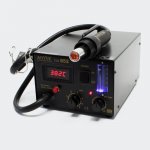
I own a couple of tube amps and I was looking for an affordable way of testing my tubes rather then going by ear. I had a heater failure with some Gold Lion 300B that took out a few parts of the the B+ circuit in my TU-8600R.


I found this Hickok Cardmatic KS-15874-L2 on ebay for about $300. The restoration itself cost about $250 in parts roughly.


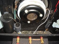
The Cardmatic arrived with about 98% of its orginal electriconic components, meaning it was only ever worked on just a few times within its 60 years plus of its life, even the power supply tube are all orginal with the Hickok name on the glass. The last owner told me it was last worked on around the 90's to bypass some bad power supply caps.


I ended up doing a complete restoration rather than a recap when I found that almost every resistor was far off spec in the power supply circuit when trying to correct the messy capacitor repairs made in the 90s.


Hickok used carbon composition resistors almost everywhere except for where it mattered like the test circuits. They used wire wound resistors there. Anyways carbon composition resistors are made by adding impurities that increase resistance, these addives have different thermal coefficient, and so when they heat up and expand and contract over time they will crack and increase in resistance, they are also very touchy to humidity and will begin to short out, the micro cracks don't help. The worst offenders were 60% out of spec both over and under the labled rating. I went with mostly automotive resistors due to their fire resistance. All tolerances exceeded. So this tester is on point in the power supply now.


Every capacitor was far off too, I refurbished the cannister caps that I could.


There was only one bad potentiometer which is used for the screen adjust in the power supply. Fortunately the rest are in point.


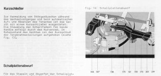
I also had to recalibrate the card reader since it wasn't functional. It was a huge pain in the ***. I cleaned every pin off and greased with conducive graphite grease. The reader has to have the perfect clearance both when the card cradle is up and down.. too high and not all the pins will engage when a card is inserted. Too low and you risk shorting out the test circuits and the pins wont disengage when the cradle is raised, it took a week of a lot of trial and error and very very small adjustments. I'm sure Hickok has some special fixture for this in the factory.


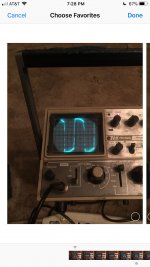
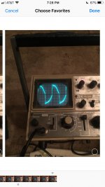
I calibrated and tested every circuit and component using a set of 90 plus cards meant for this. And it is dialed in perfectly!! Everything was double checked with a Fluke meter.


I now have a nice tester to check my tubes in my TU-8600R and my TU-8500 pre amp!

Very happy I could get this little piece of electronics history fully operational!

Tweeter Series Capacitor in Active System - Choosing Value

I’m going to attempt a design with the Satori TW29DN-B tweeter in an active system (miniDSP), and I want to implement a series capacitor as protection in the event that there is a power surge or breaker trip event that sends unfiltered signal to the driver. I’m going to go with the camp that recommends a value at fs + 200 Hz as the target corner frequency. My question is in regard to calculating the correct capacitor value. Do I want to go with the nominal impedance of the driver, or do I want to target the impedance at the cross point?

Thanks in advance.

Hot wire cutter circuitry for better speakers?

I plan to use a hot wire cutter to cut XPS foam to make speaker horn moulds.
Wire size about 0.5 mm, needs ~5 amps.
A 1 metre cutter in nichrome is ~5 to 6 ohms - so ~25 V and 125 watts.
That is easy and reasonably safe with a transformer.
In fact I even made a hot wire cutter similar to this as a one-off project for a friend's factory to cut broadloom plastic cloth.
It was decades back so I don't even remember the power requirements but commercial units are similar to what I calculate so I don't think I'm too far out.
The idea for the new project is an improved circuit that controls the power to reduce idle losses and allow closer tolerances.
It should be not too hard to monitor both the current and volts thru the wire and calculate the resistance, to use in a feedback loop to keep the temperature constant.
Anyone seen a circuit to do this?
The obvious way is a simple micro-controller but maybe a simple all analog circuit would work.
Or other ideas?

David

The Circlophone©, Germanium edition.

Since the beginning of the Circlophone project, I had always toyed with the idea of making an ultimate test of flexibility and versatility: create a vintage, full-germanium version.


I finally had the time and opportunity to build one.

  • It is an interesting test: would a modern topology like the C have been viable in the early sixties?
At the time, amplifiers were prone to thermal runaway and had to include a whole range of counter-measures like NTC resistors, compensating diodes and emitter resistors.
  • An adjustment-free, totally safe amplifier would have been a considerable improvement, but is it actually possible?
The answer is here, it is the "Steamclophone", an amplifier built using exclusively components and techniques available in the early sixties.

Some adaptations had to be made, for mainly two reasons: one is obvious, it is the different material bandgap, the other being the slowness of Ge transistors compared to Si: they are litterally orders of magnitude slower.

This required some redesign of the compensations too.

Another problem is the lack of good NPN transistors: this mandated the use of P-darlingtons for the OP, instead of CFP's.
The bias currents also had to be corrected, because of the low allowable dissipation in the VAS and driver transistors.

The result however is still very much a true Circlophone, completely self-adjusting and thermally safe.
It worked almost immediately, with the quiescent current establishing itself at 190mA, just like its silicon brothers.

Now that I have the thing working, I will measure its characteristics and post some oscillograms....

Have fun!

Attachments

  • TheCirclophoneGe.png
    TheCirclophoneGe.png
    89.5 KB · Views: 1,430
  • Steamclophone.jpg
    Steamclophone.jpg
    356.6 KB · Views: 1,371

Quest to the perfect amp! Ordered TPA3255 from Dr mordor :)

Quest for the perfect amp! Ordered TPA3255 from Dr mordor 🙂

First of all, thank you for the answers to my beginner questions in a previous thread!


It helped me decide to go for Dr mordor's amplifier TPA3255 which i'm awaiting in anticipation.


Now i'm researching on where to go from there! Hope some of you can help me with this 🙂


So i have an Akurate DS as my DAC/Streamer. This has inbuilt digital volume control, and XLR outputs that i'm going to feed dr mordors amp with.


However, if i want more inputs on this amplifier i presume i have to add an input selector board in the back. And maybe a volume control pot. How do i wire these things up?


And can i buy some of the already premade boards on ebay without messing up the sound quality? 🙂


Would love to add bluetooth as well, but i know this can bring its own problems!

Thanks guys!

Repairing PE 3046 automatic turntable

I just obtained a PE 3046 turntable that I would like to repair (ca 1974-1978). The PE 3046 turntable features automatic playing, however, I can only get manual playing mode to work. I have obtained the German PE 3046 manual (which I can't read unfortunately) as well as the manual for the similar Dual 1226.


The problem is this: there is a cam in the turntable that activates a black lever (number 155 in the attached photo from the service manual) which both raises and lowers the tone arm, as well as pushes on another lever down and sideways, using friction to move the tonearm horizontally to move it from the tonearm rest to the edge of the record (number 201). Whatever surface treatment was used to provide this friction has worn away and therefore the black lever simply slips when pushing on the lever sideways and the tonearm does not move horizontally automatically.


If I disconnect the return spring, I can get it so that I can manually place the tonearm and play a record, however, I would like this feature to work. What can be done to restore the friction? It feels like some gritty material was used to provide it. I tried to place a piece of rubber between the two but it doesn't work, it seems to require a lot of force.


If anyone has experience repairing such friction mechanisms please let me know.

Attachments

  • pe3046-page10.jpg
    pe3046-page10.jpg
    159.6 KB · Views: 180

DVM readings vs PSUD2

I'm trying to salvage a bad first build with a bit of a redesign and numbers I'm getting from my volt meter are not matching what I'm being told should be there by the PSUD software. For example, based on measuring the voltage across my 6L6GC's cathode bias resistor (SE design) I am running them at 65ma. But, if I put that value (x2) into the PSUD software, along with appropriate pre-amp tube draw I'm not getting very accurate B+ results. Now, if I drop the draw to something much lower (on the order of 50ma per channel) then the voltages line up spot on with what I'm recording on the volt meter, given the rest of the parameters being accurate.


Seems simple to me that 21.5 volts divided by 330 ohms (small design change from original) equals 65ma but I'm wondering if I'm missing something. The design (attached) plays incredibly quietly at something a bit north of these B+ voltages so worried my bias is off.........then again, could just be those 6sn7s.

Attachments

  • image.png
    image.png
    118.6 KB · Views: 111

Alpine MRV1507 - Protection blinking

Just repaired one side of the PS, IRFZ48N units. All other parts checking out all OK. Put the amp back in the sync, which takes a minutes, and it powers with 1.4A idle draw. ~98vDC rail. Everything else seems to be checking out OK, but no audio.

Power is Green.
Music is Green, I'm not sure if this is right since there is no audio connected.
Protection light blinking red which I understand may be an RCA shield problem.

RCA shields are directly connected to non-bridging speaker terminals.
RCA shields to amp ground is about 14kohms
Powered, there is no DC across speaker terminals.
Powered, referencing amp B- theres 0.74vDC on speaker terminals.

Is there a SM floating around?

Value of a pristine pair of full-range Fostex F200a drivers.

Hello all,

I have a pair of Fostex F200a drivers in good condition that had never seen regular duty in an enclosure. They have been used for testing purposes (by the previous owner) and had been in temperature-controlled storage since I bought them 10+ years ago. These are alnico full-range drivers that had been discontinued by Fostex. They were made famous by the enclose and filter design by Bob Brines known as the FTA-2000 which used to be considered one of the very best single driver speakers.

After owning them for over a decade, unused, I might sell them now but have no idea of the value. I hope that you could help me determine what a fair price would be for the pair.

Thanks.

Attachments

  • 0C92969B-1B35-44C8-A7C7-4C7855F9870F.jpg
    0C92969B-1B35-44C8-A7C7-4C7855F9870F.jpg
    633 KB · Views: 327
  • F72AABB5-A32A-490B-AD4A-E7CA35BE70D4.jpg
    F72AABB5-A32A-490B-AD4A-E7CA35BE70D4.jpg
    432.2 KB · Views: 310
  • 12F68E06-2583-4961-AE45-68275BE4489C.jpeg
    12F68E06-2583-4961-AE45-68275BE4489C.jpeg
    608.1 KB · Views: 356

Active Servo Subwoofers

Can somebody explain active servo speakers? Please explain like I'm a four year-old.

In context: I've had a number of Yamaha sw-P130's. As a result I have two working drivers which I intend to use for a separate project. However, I have utilised a P130 plate amp in a separate project. It is connected to random Sony driver. Does the active servo system require the technology to be present in both amp and driver?

Bang & Olufsen Beolab 7.1 Icepower modules reuse?

Hi All, I have a Beolab 7.1 speaker that has issues (doesnt play sound even though I get the green led light) I'm thinking as there is 3 x 125w icepower modules inside maybe I can reuse these (hopefully one or two are still ok) and put them in a Ghent case and make a nice little class d amplifier. First up , does anyone if these icepower modules are mono or stereo? I have the speaker open so I can send pictures of the modules. They seem to have a separate power supply PCB, what PCB would I need to give these modules power?
I've built an icepower Ghent case amplifier before but it had the integrated power supply and it was an easy self build. I think build is within my skill set, but just need some direction.
Thanks for letting me send this post and cant wait to here your answers / opinions.

Help with a small portable bluetooth speaker

Hi everyone,
I'm an absolute beginner with the idea to build a small portable bluetooth speaker and I'd appreciate some input on my ideas!

These are my tentative specifications:

  • very portable: around 1l net volume
  • mono (I assume one bigger driver is better than two small ones?)
  • 2-way
  • vented
  • casual listening to music and watching movies
  • bluetooth and Aux input
  • battery powered
  • USB chargeable
  • overall budget up to around A$150. Flexible if there is a good reason.

First of all, I've read in other threads that it's difficult to achieve similar sound quality / range to commercial products, as they use DSPs.
Is that true? I would like to get somewhat comparable results from my speaker.

I was thinking a 2-way, with a mid-/fullrange and a tweeter. I assume higher sensitivity is preferable as it's battery powered? Any suggestions for combos?

As far as I know vented speakers can be smaller and can produce lower frequencies. My personal (unqualified) choice would be a passive radiator, mostly because of looks but also because it can be even smaller than ported. I'm happy to use a port as well though, if it brings advantages.

I'd probably use plywood for the enclosure, how thick would it need to be for a small speaker like this?

That's pretty much where I'm at, I'd love to hear your opinions and ideas!!

Thanks in advance!

BBC LS3/5A - thoughts for computer speakers?

I've always been intrigued by these speakers, for what they do vs. what they don't do (loud, lots of bass, free of quirks - plenty of 'good' speakers I can buy for that).

I found Falcon sells a kit for about $1,200 USD. I know this is a TON of money if you just compare specs, but I am looking for something fun.
Falcon Q7 | The Ear

An easy choice would be something like the KEF LS50, but I worry I'd find myself a little bored with how...perfect(?) they are. I know that is strange to say.

Anyway, these would be used mostly as my computer speakers for background music as I work, or anything else that needs audio. This will not be my main system, but of course I could try them on my main system.

Using an ACA right now (I appreciate it because at the low levels and close distance, there is ZERO background noise vs. the Rotel integrated I am using as a preamp) and will upgrade the preamp side of things (like a Schitt Asgard with the Multibit).

Thoughts? If I want something flawed but lovable, good at low levels, think I would like these?

Passive Radiator Placement

Hey everyone,

I'm currently working on a small 2.1 sound system for a friend, aiming for a flat response and clean overall sound in as small a package as possible.

For the satelites, I've settled on using a pair of FaitalPro 3FE25 Full Range drivers, as they have a relatively flat response and excellent off-axis sound. For the sub, I am using a Dayton Audio DC160-8 6.5" Classic Woofer and a matching 8" Passive Radiator, also from Dayton. This combination will allow me to cross over nice and low, hopefully somewhere around 90-100 Hz.

I've read elsewhere on the forum about the same woofer-PR combination being used in a sub known as the Bitty Boom V.2, which is a 14" length of Sonotube with one element in either end. The gross volume of this enclosure is about 11.5L, and apparently it can reach frequencies as low as 25Hz pretty comfortably with 25g of mass added to the PR.
So my question is, basically, how much of that LF extension is attributable to the shape of the enclosure? All the other designs I've seen have the PRs mounted to a panel adjecent to the woofer, rather than directly in line with the back wave. Is there a known trade-off for this design? Is there one preferable way of doing it? I have no prior experience with building PR-tuned cabinets, but I'd definitely prefer to build either a cube or rectangular design over a tube.

Another side-note question: Can I make up some of the losses in cabinet volume (from the baskets, motor, and onboard amp) by stuffing the box with wool? Or is it preferable to just add more mass to the PR to maintain the tuning?

Any help would be appreciated!

Thanks

too much heater voltage

I was given power and output transformer, along with an EZ80 rectifier and EL84, and looking to build a small guitar amp.

The heater secondary is measuring 7.8v, and has no center tap.

If I plan on using with the EZ80, EL84, EF86 and a 12AX7, what would be a good voltage measurement without the load? And how can I lower to that voltage?

Ive seen other posts where adding resistors is suggested, but wonder if this would work for dropping 1.5v.

Is it possible to disassemble these transformers and remove windings?

Thank you

MTX RT1000D Odd Drive Wave

This amp had me scratching my head for a while because the bicolor status LED would only glow faintly on both sides with remote applied after I replaced all the FETs, but as it turns out it’s actually making both rails and has good output drive. Guess the lamp circuit needs work, but my question is:

Is it normal for these to change the PS wave shortly after startup?

When I first apply remote I get pic #1, after a couple seconds it changes to #2 which to me looks terrible but the amp seems to function this way and nothing gets hot.

Attachments

  • D7B833A5-FD77-4D71-91FA-3A3EED200781.jpg
    D7B833A5-FD77-4D71-91FA-3A3EED200781.jpg
    209.3 KB · Views: 103
  • 62933E97-D761-4BAC-ADDD-8024316360F3.jpg
    62933E97-D761-4BAC-ADDD-8024316360F3.jpg
    207.7 KB · Views: 92

Chassis volume measurement

Hi People,
I am kind of wondering about how to best construct a loudspeaker.
Now given that in the end I get some volume for the Box that I need to build. but the problem is, that when I build in the Chassis I loose some volume (Chassis cone and magnet at the minimum)
Is there any tested technique how to best calculate or measure this volume?

kind regards
huegene

Supply voltage vs THD+N

For example I'll use the LM3886 which I'm currently looking at the datasheet for. If you feed it 28v, at 8 ohms you get up to 38 watts output before distortion starts rising. If you feed it 35v you get up to 61 watts at 8 ohms before distortion starts rising. The distortion is effectively identical for both voltages from 0 to 3 watts, but between 3 and 38, distortion is almost half the amount using 28 instead of 35 volt power.

Is there an explanation for why this happens? Is this effect exaggerated in the LM3886 compared to other transistor amp chips, or is this how things always are - and the reason variable rail amplifiers exist? I always thought it was Energy Star efficiency requirements or similar

Help DDC/Streamer with SDIF3/Raw-DSD out

I'm trying to help a friend, who owns an EMM-Labs DCC2 SE and CDSD SE combo, come up with a solution on how to play DSD files from his PC or laptop using his existing (btw. amazingly good sounding) DAC.
The problem is that the DCC2 SE only accepts DSD via EMM-Labs own Optilink glass connection or via SDIF3/Raw-DSD using BNC connectors.
EMM-Labs streamer would be too big of an investment for the few titles he wants to buy that are just available as DSD downloads...that leaves the exD USB DDC as the only option I could find so far and well I didn't manage to find one of those units. Diy options are ofc very welcome.

Please I need your advice diya with this unusual problem😕

ISOBARIC: Clamshell vs Push Pull Slot Loaded

I have confused my self regarding the T/S parameters for Isobaric loading. As I understand things ....

In one version, Clamshell, the woofers are on a common baffle and mounted face to face with the drivers wired electrically out of phase (so the air space between the drivers is isobaric). As I understand it, in this case the Vas is reduced by approximately 1/2; Fs remains the same; Bl doubles; and Mms doubles. The port length would also double (e.g., in a 4th order bandpass). So far so good.

In another version, Push Pull Slot loaded (PPSL), the drivers are again wired electrically out of phase but the arranged "magnet-to-face" into a small volume that is open on one side (the slot). The "other side" would be the back volume of the cabinet. In this case there is a reduction in distortion (via cancellation) that would arise from any non-linearity between the cone moving inward vs outward.

My questions:
A. Are the T/S Parameters for the Clamshell and the PPSL configurations the same?
B. Does the reduction in distortion for the PPSL configuration also hold true for the Clamshell configuration?

My ultimate goal is a clamshell configuration in a sonotube cabinet or a PPSL in to a Tapped Horn design. But first I need to get straight on the T/S parameters.

Tube preamp with SS and Tube output?

Is this possible? I was going to put together one of Marks tube preamps into one of his low power tube power amp modules (https://frogpedals.com/). Then I got to thinking. Maybe I could also put in one of the little 10 Minute chipamps in there as well (10 Min Amp - AUD $7.00 : diyguitarpedals.com.au, A shop for all diy guitar pedal enthusiasts!). Then I would have a .75-2.5W tube amp and a 7-8W chip amp for testing my pedal builds and such.

Only problem is I'm not sure if it will work. I was going to run the output of the preamp into a switch to choose between the tube/SS sections each with a separate master volume or I could put a switch between the outputs of the power sections and put a dummy load on the tube OPT when switched to the SS side.

Any ideas?

Raspberry PI HDMI SPDIF

I'm putting together a Raspberry PI to play my FLAC music files. This will output SPDIF to a miniSharc using Volumio.
I can run this through my old Sony TV via HDMI. I am wondering if the TV is just a pass through or is liable to be doing something not bit perfect to the data.
The miniSharc resamples the data with sample rate conversion so I don't think jitter is an issue.

In using a different tap

Hi there,

I'm getting set up to experiment with using a hi fi circuit (HF60 for starters) that will be using old output transformers from a Leak Stereo 50. They are UL of course and have a primary impedance of 7K. I thought that was unusually high for a pair of EL34's in push pull but, I'm a little bit new to old hi fi tube amp practices.

What differences would you expect to hear if say, one were to hook up an 8 ohm speaker load to the 16 ohm OT tap, especially in terms of volume?

If things work the same with a UL OT as they work with non-UL I would expect the EL34 pair to see something more near 3.5K ohms as a primary impedance - which I have seen that value more typically used in amps than the 7K that the OT's are speced for.

Just to clarify, this stereo amp I'm building up is to be for a musical instrument preamped at line level that possibly may benefit from a more accurate reproduction than say, a guitar type amp - that is to be seen more clearly later on as I experiment with a few things but, I entertain the possibility that since it is an instrument playing only single notes (80Hz and higher) , it may benefit more from a greater volume output than a super low distortion percentage. We will see.

Thanks!
Best,
Phil

Custom shapes and or mass to woofer dustcap

Has anyone ever experimented with adding shapes convex/concave to a woofer cone/dust cap?

The original cap on this woofer is concave and has poor top-end frequency response.

I'm looking to increase FR an octave or more. I understand I'll loose efficiency when adding mass.

Attachments

  • IMG_3104.JPG
    IMG_3104.JPG
    246.9 KB · Views: 107
  • IMG_3102.JPG
    IMG_3102.JPG
    258.8 KB · Views: 93
  • IMG_3101.JPG
    IMG_3101.JPG
    281.5 KB · Views: 96
  • spike.JPG
    spike.JPG
    14.9 KB · Views: 103
  • dome.JPG
    dome.JPG
    17.8 KB · Views: 104
  • bumpy.JPG
    bumpy.JPG
    25.8 KB · Views: 48

6n1p VS ecc88 in Catodo Follower...current set?

Hi, I was shutting down my preamp, after I finished building it and listening to it.
I was left with the doubt on the development of the follower cathode.
I have a CCS (C4S) set with 3.2mA by trimmer.
The valve is a 6n1p gold grid - gold pin.
....but i could also a tesla e88cc as an option to be mounted.
With the voltage values ​​in the drawing I have the 6n1p grid at about -3.5v, I think, if I remember correctly.
I can do better?
I tried to center the tensions as much as possible, 138v is the practically exact goal of 275v.
I did a further research and I see that the 6n1p can also be crossed by 7 / 9mA. Are my 3.2mA few?
According to you the voltages are compatible with the assembly of an e88cc ... then I adjust the ccs to a correct current (?).
I don't want to touch the Ra of the previous stage, this maybe puts me some limits. Unfortunately I don't know how to use simulators.
Is it more important that the Vg of the CF is central to the B + or is the negative value of the grid more important?

PS: in the drawing I wrote ecc88 in brackets ... but the one I can put in it is an e88cc.
The stage preceding the follower cathode is ecc83.
I drive 3,5mt of signal cable and enter an amplifier with 20k input.

Thanks in advance for any advice.

phone mod

Hello everyone,
I need help to mod a table top telephone (no tel line but sim card instead).
I would like to take the hand free speaker signal to send it in a radio mixing desk.
It works but only for the tone. No voice...
I also would like to send a line level feed to the hand free (build in) microphone.
This is even trickier. I made a divider to attenuate (10kohms and 1kohms) and added a 10microfarads condenser to filter out the DC (needed for the electret mic).
The build in hand free speaker and mic are disconnected.

The goal is to use the hand free button to switch from hand set to the mixer and have the listener "on air".
Do you have any advice?

Thank you.

3D printing tap guides

You might need to tap holes in a plate for standoffs, or into a heatsink to mount transistors. If you are like me and are a clumsy machinist, then you have experienced the frustration of breaking a tap inside a hole that you are trying to cut threads into because you are not holding the tap handle straight. If you are lucky enough to own a mill, you can position the tap in the mill to hold it straight, but if not, you may have to do it by hand.

So I have designed these 3-D printed parts to hold the tap perpendicular to the surface of the part being tapped. The tap is inserted through the top and bottom hole, and the bottom surface is placed flat against the surface being tapped. These might be used also to help drill the holes straight as well.

This is a parametric FreeCAD model so you can change the dimensions to suit the diameter of the tap being used. I included 2 mm, 2.5 mm, 3 mm, 3.5 mm, 4 mm, 4.5 mm, 5 mm, 5.5 mm, 6 mm, 6.5 mm, and 7 mm diameter hole guides already generated with the model. A picture of the 3.5 mm model is included which is usable for 4-40 SAE or M3 taps.

Attachments

  • tapguide-CAD.zip
    tapguide-CAD.zip
    241 KB · Views: 59
  • example-3.5mm.png
    example-3.5mm.png
    23.2 KB · Views: 186

Heat dissipation efficiency for amp module

I plan to build a Firstwatt F6 and just ordered the parts and boards. The plan is to build a separate PSU unit where i can swap out different amp sections which is house in another enclosure in future builds. This means I can get smaller enclosures. But is there a problem with smaller casing/heat sink for the amp section? What do I need to be warry of?

Request for Suggestions based on specific requirements

I’ve been lurking around here for the last few months and I’ve learned a lot. I think I’m ready to pull the trigger but your personal experiences are encouraged.

About 2 years I started my audio journey. For me, headphones were the gateway drug and still a hobby that I very much enjoy. I have a small room that serves many purposes from recording/editing videos to playing video games to listening to music. The room is roughly 12x15. It’s cluttered with shelves and assorted acoustic panels. I have a listening position setup in the room where I sit about 7 feet from the speakers, the speakers are about 6’ apart from one another and they’re separated by a television.

Current setup is computer> Denafrips Ares > Woo Audio WA22 (tube pre/headphone amp) > Schiit Aegier monoblock amps > KEF R500.

What problem am I trying to solve? Variety is the spice of life. Ideally I would get something very different from the KEF house sound. I would say I fall pretty hard in the 4-5 piece band category ranging from 50’s/60’s jazz quartets to the likes of Puss N Boots and singer song writer focused acoustic music. I’m not a bass junkie. I’d say I’m mostly into imaging, sound stage, and performances. I think the KEF’s do this stuff pretty well, but I’m intrigued by the idea of full range point source speakers. The goal at the moment would be to complement the KEF’s rather than replace them.

To start out, I’ll like be using the Aegir to power the speakers. For those unfamiliar it’s a class A/B amp rated at 20 WPC, the first 8ish watts of which are class A. Not the best amp for the intended purposes, but likely not an awful option either.

So I’ve told you about the gear, about the room, and about my taste. I don’t think the frugal horn is a good fit for my room because of distance from wall, but other than that I don’t have many other rules. I could feasibly do a speaker that sits on a shelf, a speaker that sits on a stand, or a floor stander like my current R500. If you have any speaker + cabinet suggestions that you would recommend I’m all ears. I should also mention I’m in the States, I’m fairly handy with a saw, and I’m also open to pre-made or second hand options.

Thanks in advance.

Optimal Load Impedance for SRPP (Potentiometer put in Output)

Captain Aloia, regarding SRPP, said that there is an optimal load (in relation to the output impedance) which minimizes the distortion even if a little at the expense of the maximum output voltage excursion, which, sometimes, it might not even matter.

If I remember correctly, from some readings, this optimal load was equal to five times the circuit's own output impedance.
In addition to the source "Bart" ... it is something that we read very often around, this is the ideal impedance.

I don't know if he is the forerunner of this (applied) "theory".

Another example written by an environmental expert:

"The SRPP is often thought of as a circuit with a particularly low distortion, which is not entirely correct.
It is also said that the SRPP has the strange characteristic, compared to the normal gain stages, of having the distortion decreasing at the decrease of the impedance of the load, and this too is not entirely correct.
What occurs is that as the impedance of the load decreases, the distortion increases regularly, up to a certain impedance value. By further reducing the impedance of the load, the distortion instead begins a decrease and reaches a minimum, beyond which however there is a rather marked increase in the distortion.
This phenomenon has been (relatively) recently analyzed and exploited by Bartolomeo Aloia in his creations.
The knowledge of this phenomenon therefore allows to minimize the distortion of an SRPP stage simply by appropriately choosing the impedance of the load.
This becomes very interesting because the impedances we are talking about are generally quite low: for example, from the simulations I made it would appear that in a case very similar to that of "SIMPRE" (ecc88) the distortion grows inversely proportional to the load when this decreases above 50kohm, then it begins to decrease again up to a minimum placed around 15k ohm of load impedance and below 15kohm it begins to grow again very rapidly. In practice the distortion with an impedance of 50kohm is almost double that with a load of 15 kohm.

Aloia therefore in its creations adopts the technique of minimizing distortion precisely through the careful selection of the load. "


In my srpp that I have just built, I am undecided whether to put an input pot (100k) or a very low value output pot. I use a 6n6p srpp at 200vdc and 14mA.

Opinions?
Thanks 😀

Fixed bias supply with DC coupled follower

Hello,

I am currently working on an amp that uses a fixed bias supply with a source follower direct coupled to the output tube in a single ended design. The bias supply is shared by both sides of the amplifier.
I originally derived the negative bias voltage from the main B+ winding with reversed diodes, but I noticed that there was a slight hum and I didn't like the amount of heat generated in the large dropping resistor so I instead used a small transformer that i had handy that provides 200VAC/100mA.

When I set everything up, I was happy to notice that the hum was gone however, one of the output tubes was severely over-biased. With the driver and output tubes removed, I rechecked the bias supply and sure enough, instead of the maximum negative -100VDC bias I was reading around -50VDC on one side. Thinking that the mosfet was likely blown, I replaced it, only to then have the other side start also dropping voltage. OK, with both mosfets replaced, I put the tubes back in their sockets and after the warm up-- grrrrr a very loud buzzing sound.

With the tubes removed, I added first protection zeners (which I had forgotten at first) which didn't help. I then added a small break out resistor on the source of the mosfet. This seems to be beneficial for the life of the mosfets as they aren't dying now, however, the drain voltage has now started drooping into negative voltages. I am perplexed as to how this is happening.

I have made some small sketches of the schematics in question (sorry for the hand drawn aspect!) Is there something in what I have done that is obviously wrong? Surely I am missing something here...

DIY Bluetooth speaker low volume problem

Hello,
I am currently building a DIY Bluetooth speaker. I used this video as a reference: Build your own Concrete Bluetooth Speaker (how-to) - YouTube

I followed all the instructions in the video, I used all the same components (except I did my own enclosure design and used similar drivers with the same ratings). Other than that, I followed all the instructions closely, and sure enough, at the first test, everything worked perfectly.

But during the final assembly, I accidentally shorted one of the speaker output wires from the amplifier (disconnected from the drivers) with the battery pack. I saw a little spark, and since then, the speaker is playing at a very low volume.

So I bought a new amplifier (thinking the old one got fried). But after I swapped them, nothing changed. What component is damaged, then?

The speaker works normally, only the volume is low. It isn’t a transmission problem because the opening jingle is also very quiet even at full volume.

Any advice will be very much appreciated, as I am really lost at this point.:h_ache:

____________________
Parts list:
  • OEP30Wx2 Audio Module Class D Digital Power Amplifier
  • USB Wireless BluetoothAudio Receiver 3.5mm AUX output
  • DC to DC Step-down converter
  • DC-DC 5V Power Supply Module 4 Pin Isolated converter
  • B50K 50K Ohm Dual Switched Potentiometer
  • 21V 18650 battery pack with protection
  • 2x 18W Speaker drivers

2 Way Bass-Reflex Port Question

Hello, I hope you are keeping well.

Just a quick question regarding adding a flare to a recommended port size.

I am designing a 2 way speaker. I've got some rough figures (need to do some tinkering but wanted to get my head round this part first) for the sim.

VB = 9L
Tuning freq = 55hz (do plan to try get it lower later on, just experimenting atm)
Vent diameter 2 inches
Vent length 186mm (again, know this may be a squeeze, haven't finished tinkering)

Unfortunately around the 30 - 50z region, my air port velocity just exceeds 18m/s. I was reading how if you flare a port, you're good aslong as it doesn't exceed something around 36 m/s (cant remember exact figure)?

Therefore, I was just wondering how you go about adding on a flare to the suggested port length winisd has given you ? Do you obtain half the flare radius and subtract from length of port if that make sense?

I know this a nooby question and I may be missing something blatantly obvious. I had a go on flare it with no success. I really do appreciate any response, even if its stating something simple. I'm completely new to speaker designing, not the best at this sort of stuff but always up for trying new things.

All the best
Have a great weekend folks 😀
Projects by fanatics, for fanatics
Get answers and advice for everyone wanting to learn the art of audio.
Join the Community
507,827
Members
7,889,848
Messages

Filter

Forum Statistics

Threads
406,319
Messages
7,889,848
Members
507,827
Latest member
Sus12