Understanding Turntable S/N figures

Hi all,

I am interested to know exactly what sources of noise the S/N ratio listed in turntable specs is assessing. Is it all mechanical and electrical noise sources or just one or the other? In particular, is it likely to be affected materially by the standard cartridge provided with the particular model? If so, for me this would mean the figure is less useful as I would soon be upgrading the cart (within reason - obviously -40dB vs -90dB implies some significant differences in the turntable construction other than the cart).

Any info on this matter would be appreciated!

Cheers,

Greg

Monobloks, separate PSU, separate filament supply...?

The question here is how to divide up an amplifier that would be too heavy on one chassis.

1. Monobloks. Looks nice, compact, good rectifier choices, but duplicates the mains transformer and chokes.

2. Separate filament supplies. Very useful for DC choke input supplies to DHTs like 300b, 2a3, 26, 10Y, 01A etc. The transformers and chokes can be big if filament bias is used e.g. on 26 or 10Y, and the transformer voltage varies with the operating point. This solution offers flexibility and keeps chokes away from the main chassis

3. Separate PSU. This way you put a good chunk of the weight - mains transformer and first choke - on a separate chassis dividing the total weight neatly. Downside is the heater supplies can be in the mains transformer, so AC leads etc.... or convert to DC....

4. All heater/filament supplies on main chassis (unless chokes are a problem with DHTs). Separate PSU chassis for just the HT. Allows all the valves to be heated before the HT is switched on.

5. Other?

What format do you like to follow when the amplifier is too heavy on one chassis?

Star-Ground implementation for active speaker

Hi folks,

building up an active speaker from existing parts/modules, the question arose how to build a star grounding facility.

In total I need to connect eight modules which are all mounted on a large power amp heat sink:

4 power amps
a module containing differential input amps and analog cross over
+/-15V Regulator board
power amp supply
control circuit board
potentially more...

The star grounding concept as such is completely clear, so my question is about physical detail:
How do you electromechanically build up such a star ground configuration? Which mounting and connection materials do you use?

I'd be very grateful for your shared experience and for actually sharing your project picture(s).

Thanks and regards,
Winfried

"Rundfunk- und Fernsehtechnisches Zentralamt der DDR" called "RFZ"

"Rundfunk- und Fernsehtechnisches Zentralamt der DDR" called "RFZ"

Hi,

if you need some informations or schematics about amplifiers and other gear from the "Rundfunk- und Fernsehtechnische Zentralamt der DDR" you con look at this site: Home - Rundfunk- und Fernsehtechnisches Zentralamt der DDR. Currently it is only in german but i think you can use google translator.

There you can find a lot of information this company.

If you have some material about this company (schematics, pictures, papers and so on) please send me this material (as PDF or othe file formats possible). Then I can add this material on the website.

The website is continuously updated.


Best regards!

jokeramik

Tube Analogue to DSD Modulator.

Screenshot 2021-05-21 at 14.56.52.png

So after a lot of soul searching and going around in circles I finally decided to bite the bullet in a sense in creating a tube based Analogue to DSD amp. This follows the plan with the SMPS with the power being an isolated switching of the DSD output to give the final audio.

Screenshot 2021-05-21 at 15.01.09.png

I've started with the basics that I'm currently building out by creating simple first order logical analogue to digital DSD converter.

These building blocks are relatively simple to then map into a valve topology.

U2 - difference - this will simply be a differential amp using two triodes.
U1 - integrator - this will again can be two triodes.
U4 - the comparator - this can be.. you guessed two triodes.

D-latch = this can be done with OR-NOT and so 5 triodes.

At this point the output is DSD and so simply I need a gate driver, or simply a push-pull set of tubes (replacing SW2 and SW3). These simply have to be able to produce ON or OFF so they don't need to be very linear.

I still have some more work todo on the logic before I jump into the tube implementation. Specifically making the system biased to operate in 'class A' so it will be tube compatible.

There are some 'additions' in terms of functionality I could do such as make U2 the front end amplification, even making the input differential..

Ultrasound modulated uni-directional driver

I would like to build something like this:
These directional speakers throw sound in focused beams like a spotlight | Yanko Design


But I want it to be quite a bit larger, capable of high SPL. I only need it to produce audio above 5 or 6 kHz, so I'm thinking of using a compression driver for the audio part. I want to use pipes to mix the sound waves.


I was thinking of simply summing the audio and ultrasound by putting a pipe inside a pipe, both possibly having an exit throat at the same point, perhaps a flattened pipe (see attached images). Would this be sufficient to modulate the pressure waves?


I was wondering if anyone here would have any tips for me, or if anyone knows of some online acoustic simulator that could aid the design?


This is a personal project as an exercise. I looked up uni-directional drivers, and found the link.

Attachments

  • pipe-in-pipe.png
    pipe-in-pipe.png
    2 KB · Views: 276
  • flattened.png
    flattened.png
    978 bytes · Views: 281

Sealing an Old Pair of Goodmans LS3/5A's

Hi all.

I have a pair of Goodmans LS3/5A's which were not properly sealed around the terminal posts. Upon opening the speakers up to investigate I found a clump of hardened black goo covering the holes where the speaker terminal cables pass through. I suppose this was rubber which deteriorated and hardened---the substance was brittle but not brittle enough that it was easy to crack and tear away.

I've managed to remove the deposits from both cabinets but now I have a dilemma: how do I go about resealing these units? Clearly the original rubber seal wasn't a good choice: those two holes I'm trying to seal are aprox 10mm in diameter and are just there to allow the speaker cables though (these use the old screw type connectors (photo attached).

The first thing that came to my mind was silicone like that used to seal a bathtub but I really have no idea if that is appropriate or if it will breakdown the same way the original rubber did after a couple of decades.

All advice appreciated. Many thanks.

oTqW1bq.jpeg

Passive 'Stereo Blend' control for overly hard-panned recordings?

I, like others before me, have noticed that it's annoying to listen in headphones to recordings with loud sounds panned hard to one side, left or right. For me, it's worst with midrange sounds like lead vocals, electric guitars, solo horns, drum sets play from one side only. It's like someone shouting at you into one ear.

I rigged up a Stereo-Mono switch, which was easy enough and didn't cause any degradation I can detect. I find myself using it on early stereo records from the 1960s, especially Blue Note and Prestige jazz records. (It can hurt when Elvin Jones takes a wild solo in the right channel!)

I'd like to experiment with a passive Blend control, preferably infinitely variable so I can dial in how much the stereo image is reduced towards mono.

Some old receivers and preamps had a Blend control that allowed you to switch from full-width stereo to constricted width stereo, to mono. Some had Mono-L or Mono-R settings, so you could hear just one channel in both speakers, which I don't think is necessary for everyday listening.

I'm surprised I found so few examples on the innerwebs. I've attached a scrawled set of schematics showing three simple examples.

Ex A: Lifted from a harman-kardon TA-5000X tube receiver. It uses a dual-gang 100k potentiometer. I assume linear taper.

Looking at the pots with connections labelled top (1), wiper (2), bottom (3):

I think this would only work if the top (1) connection of the left channel pot goes to the Left channel input, while the (3) connection of the right channel pot goes to the Right channel input.

The bottom (3) connector of the left channel pot and the top (1) connector of the right channel pot are shorted and connected to signal ground.

The two (2) wiper connections are shorted together.

This arrangement would put the two tracks connected opposite from one another, so that when you turn the knob clockwise, the left channel track moves clockwise while the right channel track moves counterclockwise.

When you move the knob all the way clockwise, the two wipers will be grounded, and the two channels will play in full stereo.

When you turn the knob all the way counterclockwise, the left and right channels will be shorted together, with each 100k track loading each channel to ground, so the two channels will be blended together into mono.

Ex B: I found this on an electronics hobbyist forum. Uses a single track 10k ohm pot connected between the channels, preceded by 1k series resistors, one for each channel.

Turn the pot full clockwise and the two channels are shorted together (mono). Turn the pot full counterclockwise and the wiper is shorted to ground, leaving the full pot resistance between the two channels (stereo). The pot is not connected to ground.

Looks nice, but will this inevitably leave some 'bleed' between channels, causing permanent reduction of channel separation? (That might not be a problem with headphones. How much separation do you really need?)

Ex C: Lifted from a cheaper harman-kardon tube receiver (TA-3000). It uses a single 2M pot with its top (1) connector left disconnected, wiper (2) connected to the Left channel signal, and bottom (3) connection to the Right channel signal.

It looks like this one attempts to keep the two channels from blending (bleeding) too much by using a high value of resistance. Does such a high resistance introduce enough capacitance to cause attenuation of high audio frequencies?

Are all of these doomed to failure for one reason or another, and that's why you never see this kind of control?

The source I'm using is a Raspberry Pi with an Allo Boss DAC (output Z probably well below 1k ohms). The load is a tube headphone amp with a 50k volume control pot, or an O2 amp (10k vol control). I'm going to try to wire a box up today and give these controls a try. I'll post results if I find anything noteworthy.

Thoughts?
--

Attachments

  • Stereo Blend Controls.jpg
    Stereo Blend Controls.jpg
    316.8 KB · Views: 215

BSC.... the final... Step! Am I almost there?

I'm helping my father revive some old cabinets my grandfather had made for speakers in Hobart, Tasmania, circa 1960-something. He's kept them for all these years and we just pulled them out of storage. The timber (teak) is in beautiful shape as are the front grills - I love the retro look. The drivers however are beyond saving. The timber for the baffle will be replaced to suit the replacement drivers.

I've built Frugel Horn mk3's to date but this is my first attempt at a multi-way speaker. The front baffle is 330x610mm, tweeter is an SBA SB29RDC-C000-4 and woofer is an SBA SB23NBACS45-4. Enclosure volume is ~41L once the drivers are in there.

I've simulated the Baffle and enclosure and am fairly happy with where I've got to so far - my concern however is the roll off from ~300Hz. The speakers will be in corners so I expect there to be some room gain... Anything I try only results in the low end dropping or the mid-high dropping, requiring much more power (the amp to be used is fairly low powered). Without fully understanding enclosure effects, my hope is that the total SPL increase indicated in the enclosure chart from 300-50Hz will compensate, but again, this is a gap in my knowledge.

What can I do about this? Additional comments on impedance and phase are welcome too. Target XO is 1750Hz 🙂

Attachments

  • XO.PNG
    XO.PNG
    370.6 KB · Views: 239
  • enclosure.PNG
    enclosure.PNG
    321.6 KB · Views: 237

Wharfedale Jade 1 DIY repair/rebuild

Hi all,

I am trying to source driver units and perhaps crossovers for a DIY repair of Wharfedale Jade 1 speakers.

The sorry tale had me playing an Audiolab 8300 cd player directly to twin power amps inadvertantly set near max volume. They have been over driven and it is a question of what isn't broken. No sound is never a good sign as is nothing like the proper sound.

How you may help is in a where to buy context. Here are the driver details of this three-way
Tweeter is a Cambridge Audio D-951
Mid range a Cambridge Audio D-916
Woofer Cambridge Audio D-910

I have just obtained a multimeter to continuity test to prove the damage if you will.

I have no idea on prices or where to buy here in UK. Have written an email to Wharfedale, nothing back yet.

I would like to have a go at even upgrading these with a new build. Advice welcomed. Thanks

Wilmslow Audio TL12/Prestige problem

Hello, I would greatly appreciate any help solving a distortion problem in the TL12s I am building.
There is a significant sibilance at the HF end of the ATC SM75-150 mid range speaker. It sounds as if the speaker is mounted on a sheet of thin ply rather than the 1" MDF baffle it is securely bolted to, I exagerate as it is only noticeble on quiet passages, particularly piano music. And the distortion is present even when the speaker is on the bench.

Both speakers suffer the same problem. I have no reason to suspect a problem with the amp so I suspect the crossover. It is the standard WA Prestige Xover design but I am using (on the adviceof WA) the Scanspeak R3004/662001 (4 Ohm) rather than the usual D2905/9900 (6 Ohm). I note WA have increased the series resistor to the tweeter to 1R5 rather than 1R. The only other changes they have made are to the mid circuit: 1R rather than 1R2 on the series resistor and 1R5 rather than 1R2 on resistor in series with the 6.8uF cap. I am sorry to say my understanding of Xover electronics is very poor.

Until I can remove the distortion there is no point in seeking further refinements.
If anyone can provide advice on this problem it would be very helpful.
Thank you.

Q-conv, SE + Class E edition

A few years ago, I presented a small resonant converter, the Q-conv:
https://www.diyaudio.com/forums/power-supplies/286078-resonant-hv-converter-conv-post4599222.html

This version uses the same principles and has similar features, applications and specifications, but it is somewhat simpler, thanks to the single-ended power section and a minimalist control circuit.

The resonant principle allows a "soft" operation, without large amplitude transients, and does not require custom magnetics: a standard, two-terminal choke is sufficient, and in applications where non-isolated input and output grounds are acceptable, it provides a simple and quiet solution.

This is the circuit:

attachment.php


And this is the output waveform (unloaded) on the tank circuit:

attachment.php


This is the same waveform under full load conditions:

attachment.php


The waveform is essentially a sequence of sinewave cycles, separated by variable-length zero-crossing "pauses".
In addition, when the output is loaded, the rectifying diodes slightly clip the tops, but compared to a conventional, switching converter it remains very benign.
With the values indicated, the operating frequency is comprised between 50 and 80kHz.
The circuit is designed for an output power of 10~20W, but there is no lower limit. Going higher would also be possible, but it is probably not advantageous because of the limited efficiency: 74% @15W.

Here is a pic of my prototype:

attachment.php


The inductor is based on an unholy hybrid between a cross-core and an old potcore, because I didn't have a suitable standard inductor available, but basically, any standard 56µH/6A power choke would work (and would have lower losses than this one)

Attachments

  • QEconv0.png
    QEconv0.png
    29.1 KB · Views: 353
  • QEconv1.jpg
    QEconv1.jpg
    469.7 KB · Views: 343
  • QEconv2.jpg
    QEconv2.jpg
    303.2 KB · Views: 340
  • QEconv3.jpg
    QEconv3.jpg
    330.8 KB · Views: 343

Denon PMA-700v repair help

Hi all

I purchased a Denon PMA-700v for parts but decided to see if I could get it working. I am a beginner in electronics and have hit my knowledge limit and was hoping someone may be kind enough to offer some suggestions.

The amp had one channel blown and I spent ages removing and testing components. I replaced the output transistors (originally 2sa1104/2sc2579) with 2sa1943/2sc5200 and driver ? Transistors 2sa1306/2sc3298 with mje15033/15032.

I powered it up with a variance and dumb bulb tester not problems. I then kept swapping higher wattage globes until I had a 1.1 amp current limit. Both channels produced great sign waves using dummy loads.

I then thought I would remove the dim bulb tester and ramped up the variance to 240v no problem. I hen turned up the volume u til I reached the previous limit using the dumb bulb tester (9.8vrms, 27vpp) with no issues. When I increase the volume some more to 12vrms R560 burns and all output transistors are killed.

ANy suggestions as to why this may be happening. I did have a relay issues that appeared to be a broken solder joint I fixed. Any help appreciated, it appears the outputs die first ?

Richard

Attachments

  • 741FF869-1264-443F-8D64-41C3E2A65954.jpeg
    741FF869-1264-443F-8D64-41C3E2A65954.jpeg
    671.2 KB · Views: 472

Mains intererence suppressor (PANDA)

I have a small box that says "Mains interference suppressor", above which there is a label "PANDA - distributed by Pact International Ltd".
On the side of the box it says "This unit is suitable for audio & hi-fi equipment".

There is a mains plug (UK type), and the box has a socket for a standard UK plug.

Does anyone know about this? Is it worth adding it to my system?
How can I test it and see what it does?

Thanks. 🙂

FS: P-Audio IMF-HP-10W - 10" 100W 8 Ohm drivers (for Boominator)

I have four of these drivers, which I bought from Blue Aran to make a Boominator. I never got around to it, so they've never even been opened. Offers around £30 each plus £10 each for postage (in the UK). International shipping possible, but might be expensive (they're about 3 kilograms each).

I have tweeters as well (see separate listing),

SIT-3

I always wanted a PASS amp, but didn't really have the cash for one. I heard a SIT-3 that was factory and really liked it. I know we can build a 3X, but I wanted to give something back to one who has given us so much, and also have one direct from Papa.

I went looking for a SIT-3 and could not find one in stock, so I gave Kent a call and asked if he could find one. He did the legwork and came back with, what is likely, the last SIT-3 still in the box/wild.

It just so happened Fred Kat/li had one left in a box and was willing to part with it. I jumped on it and it's shipping out of CA and will be here Friday.

I'm excited to have an amp from the shop, I might even build one and do some A/B stuff and measurements. Heretofore, I never had the real deal to test.

I know this isn't a huge money deal and Nelson doesn't really need the cash especially the little from this, but it is still nice to have an original from his shop. 🙂

JT

The CHEAPEST speakers you can build

This is a thread to help me keep track of the 'cheapest speakers' I build. Feel free to add your own.

Rules, parts must be new and available. Prices in USD.

Tweeter = $1.98

https://www.newark.com/mcm-audio-select/53-805/3-x-7-piezo-horn-tweeter/dp/96K1143

Woofer = $9.18

https://www.newark.com/mcm-audio-select/55-3231/70w-rms-4-ohm-rubber-surround/dp/43W7872

MDF box = $10 (30 liters)

Rear Terminal - $2.84 (could go a $0.41 version)

Optional = 3mh inductor (common mode choke for a PSU? ~$3)

Glue = $1.0
Staples = $0.50
Wire = $0.50

It still makes it ~$30 per enclosure. hmm

Don't worry, the dog is deaf.

The graph is 1/6 smoothing


Can it REW? yes

Sound = OK with/without the EQ

Attachments

  • roadkillEQ.jpg
    roadkillEQ.jpg
    116.4 KB · Views: 694
  • roadkill2.jpg
    roadkill2.jpg
    99.3 KB · Views: 684
  • roadkill.JPG
    roadkill.JPG
    83.7 KB · Views: 1,164

front baffle width & driver size relation

How does the size of the driver relate to the width of the baffle in a conventional surface mount configuration with regards to where in frequency the baffle step correction needs to kick in and to which extent?

Is there any relation at all or is it simply a function of wavelength? In other words, will a 6,5" midbass driver get more support from a 600mm wide baffle then its equivalent 15" due to the greater relative baffle area to driver size (or Sd)?

Audiolab 8000CD: still displays ERROR after laser replacement.

Hello,

the issue is about Audiolab 8000CD, made in England, one of the first production series I guess. One day after switching player on I heard only short rasp and then saw ERROR message on the display. Obviously player was not able to read CDs anymore. I replaced whole CDM12.4 mechanism with only poor result: player started to read CDs, displayed number of tracks on the CDs and total time but after choosing particular tracks ERROR was displayed again. I thought that CDM12.4 is not broken despite brand new (I think this was not original Philips) and replaced it again with new piece - this time laser/optic unit only. Symptoms are exactly the same like after first replacement.

Any ideas ? Could the problem lie in the mechanism / laser itself or should I look somewhere else ? I read that these first production pieces of CD8000 suffered from 'some problems' ?

Best regards and thanks in advance for any hint,
toms789

Kef B139 refurbishment

Hi, new here so finding my way! I run vintage Cambridge Audio R40/50's and Lentek Monitor speakers all of which use various iterations of Kef B139s. I have spare 'later' ones for my Lenteks when needed so no problem there. The Cambridges have the earlier 'racetrack' versions which require a different opening in the baffle to the later ones. I have acquired a pair of racetracks but they are rough and I want to rebuild them. Those of you who know these speakers will realise that 'normal' rebuild procedures do not apply because the 'cone' is a solid lump of 'styrene. They can be rebuilt, I've had one done in the past but the price is exorbitant, anyway I want to do it myself. So has anyone any hints and tips which may help please.

Bad capacitors. Bad design or bad caps?

I have a Denon DN-X1500 mixer and the output was a little crackling, I have noticed that 4 out of about 50 capacitors are bulging on that one board so I was going to replace them.

Question: Do you think I should replace them all? Or replace all the caps in the area of the bulging ones? Or just replace the faulty ones?

Question: is it due to faulty caps or bad circuit design causing them to malfunction? How do I know this?

Oh and also the mixer does get quite warm in use BUT I don’t think it means it’s faulty as it’s a common thing with those models meaning it’s just what they do. (bad design maybe causing them to fail prematurely)
The faulty caps are SMG 35v 100uf which only 4 are bulging out of about 8 on that board but the rest could be in a different circuit.
I have attached a photo of the board, about 99% of the capacitors are the one brand SMG I hope this brand is a reliable component because the boards are riddled of them 😱


The capacitors with the red dots are the bulging ones and the ones I have circled are the same value as the bulging ones.

Any thoughts are greatly appreciated!! Thankyou 🙂
An externally hosted image should be here but it was not working when we last tested it.

My subjective results from A/B testing 7 in-wall speakers (and 2 other speakers)

I'm very much a beginner to speakers and have a lot to learn, but here is the results of some testing I recently did to select speakers for my living room TV audio setup. Purely subjective, I just listened to them with my ears to decide which ones I liked the most. I got fairly cheap speakers.

I got 7 different in-wall speakers that I could try out to select the ones I liked the most. I built a simple connection box with banana plugs to use as a speakers selector. I connected the speakers to the center channel and played some of my favorite movies and listened to the actors' voices and other sounds in the movie like doors closing etc. I was listening for the speaker that made the scene in the movie sound the most like it happened right there in front of me. I repeated some moments and sounds many times over a couple days with sleep in between to "reset" my ears (very unscientific). The amplifier is a Pioneer VSX-D509S I got off craigslist and the input was Dolby 5.1 over optical S/PDIF from my TV.

First two enclosed in-wall speakers. These come in small plastic enclosures and I could listen to them without mounting them in anything. They sounded so bad compared to the other non-enclosed ones even played unenclosed in free air, so I returned them immediately. The main problem was the tweeters, they sounded to be severely lacking in the upper range. They're not even in the photo.
I built simple boxes out of particle board to mount the unenclosed in-wall speakers in. The boxes have a volume of about 110 litres, except the shorter one that's made of what was left of the three 4'x8' particle boards. I used double sided foam mounting tape around the edges to avoid having to engage the plastic drywall mounting hardware the speakers have (somewhat irreversible). I tested them with their grilles on but took them off for the photo. Forgot to take the grille of the Klipsch KSP-C6. The Klipsch KSP-C6 and the Dayton Audio B652-AIR are not in-wall speakers but I added them for comparison.

qpiC06v.jpg

  1. Monoprice Alpha In-Wall 6.5in
    This one and the other Monoprice one had distinguished treble, I suspect because of the 1" tweeter and the 3" tweeter? They sound to me to both reach the highest frequencies (subjective), but also the whole treble sound range sounds great. The Monoprice Alpha 6.5" surprisingly has deeper low end than the Monoprice Caliper 8". I don't know why but I compared these two a lot and the Alpha 6.5" has better low range. The Monoprice 6.5in is my choice any day over the Monoprice 8".
  2. Polk RC65i
    Of every speaker I tested this shared 2nd place of overall best speaker with the Monoprice 6.5 (subjective). It had the most low end and mid range of all the speakers except for the Klipsch KSP-C6. It beat both the Monoprice 8" and Dayton 8" in low end. Maybe the Polk driver was just better at moving air than the other ones, even though it's a smaller diameter? This opened my eyes to that some drivers can really be a lot better than others. The only reason this speaker did not take a solo 2nd place was that the Monoprice 6.5 had better upper range treble, not by a lot but the Monoprice 6.5 was noticeably "brighter".
  3. Dayton Audio ME825W
    Very disappointing. 2nd worst of all the speakers in the photo. Very lacking in midrange, very noticeable in voice reproduction. Voices did not sound natural. Treble was greatly beaten by the Monoprice speakers and the low end was only ok.
  4. Monoprice Caliber In-Wall 8in
    Treble great but very disappointing in low end, and disappointing in mid range. I suspect that the 8" driver in this speaker is just not good?
  5. Dayton Audio ME525MTM
    This was the worst of all the speakers in the photo. No low end, bad mid range, sup-par treble.
  6. Klipsch KSP-C6
    I bought this older speaker off Craiglist. This speaker beat every other speaker in the photo. It did almost make the movie sound like it was happening right in front of me. I'm very impressed by this one. Voices sound the most real through this one and it also has the deepest low end of all the speakers I tested. Treble is great. Only the very highest frequencies are possibly reached by the Monoprice 6.5in which are not reached by the Klipsch KSP-C6 (not entirely sure, the Monoprice 6.5in just sounds like it reaches slighly higher). I'm not sure why this one reaches deeper than all the other ones with it's 6.5in drivers. Is it because of some resonance influenced by the enclosure volume or is it just a better driver?
  7. Dayton B652-AIR
    Good treble but lacking in upper mid-range (subjective). Voices did not sound as natural as the Monoprice speakers.

My subjective ranking of how much the speakers made the movies sound like they were happening right in front of me:
  1. Klipsch KSP-C6
  2. Monoprice Alpha In-Wall 6.5in shared 2nd place with Polk RC65i (I have a hard time selecting between these. Polk is better in mid and low range but Monoprice 6.5in is fairly good in mid and low range but is brighter than the Polk)
  3. Monoprice Caliber In-Wall 8in
  4. Dayton B652-AIR
  5. Dayton Audio ME825W
  6. Dayton Audio ME525MTM

Conclusion
I learned that different drivers really can sound very different, and that a 6.5" diameter driver can have deeper low end than a 8" diameter driver (this one surprised me, please tell me if this can't be true, as I only listened using my ears and have no measured data to support that).

Since I love the Klipsch KSP-C6 so much I think I'm going to have to take the drivers out of the original enclosure and either create a new elongated equal volume enclosure that can fit in my wall, or try mounting them directly to the wall in a infinite baffle like setting (? please advise on this, I think I'll have to check out the suspension properties of the drivers).

During my journey into speakers so far I have learned that drivers are probably the most important part of a speaker. Please advise if otherwise. The enclosure is mostly there to baffle the canceling waves coming from the backside of the diaphragm. The enclosure only supports the driver up until the limits of the driver. Except for one resonant frequency perhaps where the enclosure will amplify that specific frequency. This is my understanding so far and I do want to learn more. I've only dealt with sealed boxes, no ported boxes.

Anyway, thanks for reading and hope this will be useful to someone looking at in-wall speakers.

Edit: After listening to these again a 3rd day I realize the Monoprice 6.5" does not go lower than the Monoprice 8", I think the 6.5 might be louder in some frequencies of a low pitch human voice but when you go lower the 8" does actually seem to play slightly louder in than the 6.5" in those frequencies. Only trust real measurements!

Formula for pipe Q

Hi All,

I had read somewhere that there's a formula which relates pipe length to circumference and cross sectional area for determining the Q of a pipe. Can anyone provide the formula or point me to a link? I tried to Google this, but was unsuccessful.

I'm evaluating a design for a Hegeman style subwoofer, but need to adjust the pipe dimensions to better fit a larger driver. I'd like to find out if there are any constraints I'll need to contend with.

5,000 hours and going, The Cossar 300B

Hello Everyone!

Feels like it's been a while since I've posted anything here, Anyways I've been testing some 300B that I bought back in July of 2020 from Victor. I'm talking about the Nature Sound Linlaitube 300B Black Plate.. now rebranded as Cossar.

If your not in the mood for reading I'll say it here... The Cossar 300B Black Plate are by far the longest lasting mid range 300B I have ever tested!! Up until now tube longevity was mostly dominated by JJ and Psavne with around 2,500 hours roughly. The sound signature of the Cossar 300B Black Plate are somewhere between a JJ 300B and a Gold Lion 300B, it doesn't have the strong bass of the JJ or the high rich highs of the Gold Lion, it's just a well balanced tube.

eU2UrEk.jpg


Now for those of you who are up for some reading here are all the details!

Back in July of 2020 I had one of my Gold Lion 300B lost half of the heater. Thankfully it wasn't catastrophic this time. Victor had recently posted about some new tubes he was offering from a new company. I was very interested in trying these out especially from a new player in the tube market. I ended up going with the Cossar 300B Black plate.

I received tubes that were well above my expectations. Especially for its very modest pricing! It's the very small details that let you know if a product is made with care and it makes sense since Cossar was started by ex Psavne folks. Like Psavne they make sure each tube is alike.. meaning the labeling all face one direction, and even the internals all of the tubes are aligned the same, if you care about aesthetics then you will like these details. Also the construction quality of Cossar tubes feel nice and strong too! But these are just the things you notice from the outside.

Before slapping these tubes into my TU-8600 I needed to make sure that I had some way of testing these tubes before and after. Fortunately I was nearing completion of a major 2 month long restoration project I was working on over the summer of 2020. I fully restored a Hickok Cardmatic KS-15874-L2 tube tester.. every single capacitor and all resistors (except a few wire wound resistors) were replaced, it was a massive undertaking considering that it was 90% stock and someone had made questionable repairs around the 90's to get this tester limping along for a few more years. Functionality was was tested using some 90 plus program cards that tests every circuit and components of the Cardmatic, and it passed with flying colors!

oov14aT.jpg


Another thing I needed was a way to keep track of the hours on these tubes and I looked at logging hours manually or something like that and maybe even a meter on the wall or something... but then I realized I had a brand new TV that I had just bought before Christmas of 2019. Through the Samsung app on my phone I can see the service hours on the TV... and my TV is always on when the TU-8600 is on. even when listening to my vinyl, I always throw on a visualizor to go with the music.. one is not on without the other!

Originally I was going to test the tubes every few weeks or maybe even monthly but in the end I decided against that..I would just run the Cossar 300B until they died, I didn't want to mess with them too much.. I was expecting them to last about 2,500 hours maybe less... but here I am almost a year later and the Cossar 300B are still pumping out sound. They are slightly above the 5000 hour mark let's see how they are doing!

Here are the test conditions under which they are tested through the cardmatic, as you can see it tests for Plate current. I allowed each 300B to heat up for 30 minutes before running the test.

sNr2x6w.jpg


So back in late July my TV only had 2193 hours, this is our starting point.

erGnMXO.jpg


I measured each tube fresh out of the box.

Cossar 300B #1 measured 66mA
Cossar 300B #2 measured 69mA

So not bad, very closely matched in plate current!

Now with 5,000 hours on the tubes

4mF3134.jpg


Cossar 300B #1 measures 61mA
Cossar 300B #2 measures 64mA

So output has obviously dropped but only my 5mA each. These tubes are still good!

For the price I don't think you could find a better tube. When you go with cheaper tube you have to make sacrifices in materials and construction quality. Cossar is making some top notch heater filament here while keeping quality high and what you get is a very well balanced tube!

Highly recommend!

My next test on these tubes will be at 8,000 hours!

What is a decent transformer company available in the US and where to buy them?

What transformer brands are good, but not incredibly expensive? I want something better than Hammond, maybe double the price. I'm going to make a 300B SE amp and I'm having a surprisingly hard time finding something.

Also, is it worth paying for a more expensive power transformer? I understand how the output transformers will perform better or worse, but does power really make any audible difference between brands?

Why did Marantz do this?

So I understand the star topology and why they would ground the op amp and first input drivers separately, but alas something is amiss!

In the schematic, both op amps are wired the same and tied to case ground (0v on the primary), while the rest of the driver is tied to 0v on the secondary. However in the diagram, L and R are wired differently. Am I going crazy or is there a reason they did this? I verified the traces on the board and they agree with the diagram rather than the schematic. Many thanks.

I have highlighted the grounds and the ground-ties. The red circles are 10ohm resisters between the two grounding arms.

SM6100SA.png

Converting old tube radio into guitar amplifier with few addons - help needed

First of all - a kind and big Hello! to everyone! 🙂
I hope I found myself in the right place to talk about such ideas and obviously to ask questions in the search of answers and solutions. I'm happy to have found this forum.

I'm in my 20's doing some electronics as a part of my lifetime hobby. Usually it's digital, less analog and hardly ever tubes, so I'm not that experienced with them and usually can't understand the bigger theory. I have made a few amps, but these were more of a "kit" than "design".

~~~

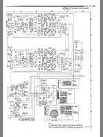
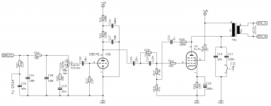
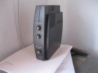
Recently I wanted to make myself a cheap guitar amplifier/combo of a kind for home practicing, so I found an old tube radio which isn't functional. This gives me most of the construction basis, together with a speaker, output stage, some preamplifier and a power supply, not mentioning the whole box. I have a bit of trouble understanding it though, so I'll attach the original schematic for it - see Sch_Original. I also added some markers which will come in handy next.

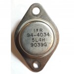
All the signal tubes (4 total) here have a rimlock base (B8A) (excluding the magic eye which is not relevant to my trouble) and I would really like to keep it that way. So, I found tube types that might be useful. I'll refer to each one later.

- EF40: a precedessor and equivalent of later EF86 - looking forward to an input stage with it;
ECC40 - instead of ECC83/12AX7 types and the one triode from EBC41;
EF42 - for reverb circuit instead of EF80, explained later;
EL41 - output stage of below 5W.


Regarding schematic, firstly I would like to try and leave the EM34 for later usage as a crude VU meter, maybe adjust its sensitivity. Then, my instinct says to cut the connections marked with orange X-s and connect input jack to one of the points indicated by the green or blue arrow. By doing this I would probably have a functioning amplifier with a drawback of its frequency response. This gives me the circuit on Sch_1.
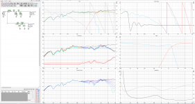
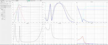
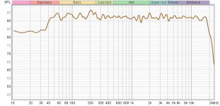
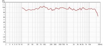
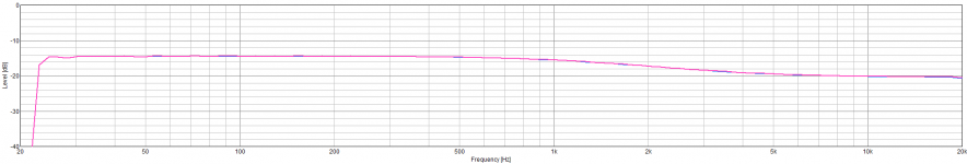
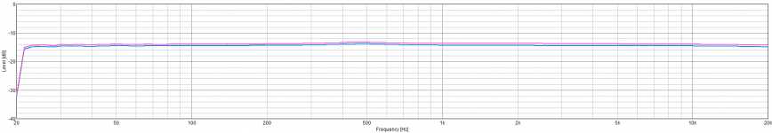
A question arises: What is actually happening here with all the capacitors, filtering and feedbacks and is it worth keeping for a guitar usage? I simulated this circuit with the triode only and it seems to alter bass response on low volume (5dB increased gain up to 300Hz), in the middle the frequency response is quite flat, and then it increases 300Hz-4kHz by 2dB on max volume (all values approximate - I'll skip the graphs for now).

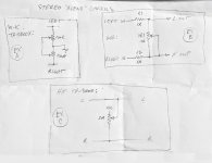
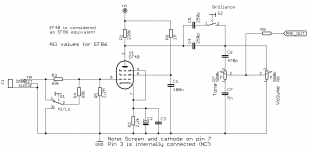
Then, the input stage, where I somehow look towards pentode input. I probably can substitute EF86 with EF40, which is said to be a precedessor and almost equivalent tube - not, that I am right, but looking at the datasheets we are really close. The schematic for this stage, probably found by me long time ago from some other guitar amplifier, is most probably to be the one shown on Sch_2. On this part of my idea I hardly have any doubt, and if any, it's the R9 resistor value and further integration with reverb stage.

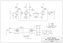
The reverb stage - I found this nice idea: LINK . Also attaching the schematic as Sch_Revb.
The first concern here is swapping EF80 for the EF42. Why EF42? - I tried to compare the tubes' Typical Characteristics and EF42 seemed to be a close one. Using it would probably need some components adjusting around it; it seems to be a basic pentode gain stage which should be even possible to recalculate. Am I right to this point?
Another trouble is, how to integrate it with the input stage? Am I correct when I think, I can 'delete' the input triode and connect the "Dwell" potentiometer after input stage? But what about the "Mix" potentiometer? EF40 (input stage) is cathode biased, so copy-cat-ing after the input triode from this design is a no-go. I wouldn't want to exceed 4 tubes in total because of the current draw from power transformer and rectifier tube, AND heater supply. Also, based on previous simulation, the EL41 needs a fairly big amplitude to drive it, so the reverb recovery triode probably won't do it. This is very troublesome for me and I'd be very thankful for any ideas.

Next and possibly last is the power supply and output stage. I noticed that usually the screen grid (second) of output tube is connected through resistor in some way, supplying it with lower voltage. Should we alter it or leave as is? The EL41 tube datasheet says Vgs2 = Va = 250V for a SE class A amplifier - so maybe it's correct. 😀
The matter of power supply is, most if not all tube designs use a multi stage filtering which also gives multiple voltages for respective gain stages. Should we leave it as is or change to "the standard"? I'm having in mind the AZ41 tube which is specified for output capacitor of 2x 50uF max only.

At the end I would expect the signal path to be: EF40>ECc40>EF42>Reverb>EcC40>EL41 with controls such as Volume, Tone (somewhere on the way, not necessarily with the input stage), Dwell+Mix and Master Volume (if it has any sense). The longer I look at it though, the more I doubt it is achieveable. Maybe I could squeeze somewhere a subminiature tube if another stage would be needed somewhere? Maybe a MOSFET in a place it won't alter the sound? No idea here. 🙁 (wouldn't want any semiconductors though)

For any questions with actual sound, I'm looking for just a little distortion, but mostly clean sound. If the gain could be changed for more distorted sound with a switch, I'd surely take it! I'll also leave the original speaker in hope of some fancy "vintage" sound.
Let's also say I will not be using any old capacitors, as the original 70 years old ones need replacing just from looking at them. Also please do let me know, if I am forgetting something.

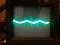
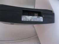
I will be plugging the radio and measuring its working conditions - voltages and currents - in a few days, so it will help in determining this project feasibility and basic parameters.


All kinds of help, whether it is a straight solution, example, suggestion or some article to read, will be greatly appreciated! In no means though I am expecting a ready fix and I'd rather learn than copy.


Many thanks to you all and everyone for any input to my post. 🙂

Cheers,
Jakub

Attachments

  • Sch_Original.png
    Sch_Original.png
    376 KB · Views: 391
  • Sch_1.png
    Sch_1.png
    47.7 KB · Views: 414
  • Sch_2.png
    Sch_2.png
    36.1 KB · Views: 451
  • Sch_Revb.png
    Sch_Revb.png
    21.1 KB · Views: 366

Overload detection circuit for UPC1237

Hello guys, I'm working on a loudspeaker protection design based on UPC1237. In it's datasheet there isn't provided any example of overload circuitry.
Designing such a circuitry isn't an easy task because there are lot of variables that should be considered in it since different amps work with different voltages and etc..

I have attached the M9 Amplifier schematic from "Analog Metric". this design benefits from upc1237 + overload detection circuit.

I want to know if it's possible to use and adopt the overload detector circuitry introduced in the M9 amp for another amplifier? say a MOSFET one like the Bora jagodic's designs.

Attachments

  • M9 skem.jpg
    M9 skem.jpg
    634.5 KB · Views: 3,467

Visaton G 50 FFL middome driver

Someone asked me to design a 3 way speaker with a middome. So i started looking what is arround (not much it seems) and found this Visaton G 50 FFL middome.

I can't find any reviews or user reports from it but the specs look very good. Anyone got experience with this middome? Is it any good? I know they fell out of favor as they are hard to use it right to modern ways of speaker designing, but this was an explicit demand from this guy.

https://doc.soundimports.nl/pdf/brands/Visaton/G 50 FFL/pdf_Visaton_G 50 FFL_1.pdf

Problem with 100Hz high frequency parasites (100kHz+)

Hello all, I have some few problems with my tube amp. The most important one is those nasty high frequency parasites (more than 100Khz) after my EF86 first stage. You can see it on the picture (5mv/div, 5ms/div) (the 100hz noise is clearly audible, I dont ear the 50hz one)


I guess it's because of the current rush in the main reservoir of the power supply, it stops as soon as I stop the amp. Those parasite are not present in the output of the power supply.

What should I do to get rid of this ? Filter it after the preamp ? adding some resistor before the main reservoir (right now there is 220ohms on a 150μF cap, I fear that more could be too much) ? A small inductor before the reservoir ?

I feel like filtering is would be the better solution.


Thank you really much for your attention and your help !
Regards,
Simon

Attachments

  • 177741344_2885909148402645_2682963666644186585_n.jpg
    177741344_2885909148402645_2682963666644186585_n.jpg
    94.3 KB · Views: 232

15 inch bass for sealed cabinet, suggestions needed

Hi everyone

What would you recommend as a 15 inch bass driver for strong deep LF output in a sealed 50-75 litre cabinet?

Upper crossover will be around 200 Hz, as front main Hifi speakers, secondary use as front HT speakers.

There will be subs, but I want these to run as extra subs, and hand over at the lowest frequency they can. DSP will be available, so that might factor in to your thoughts.

Sadly, money is a factor, so premium and affordable alternatives are sought. I don’t have a hard dollar limit, but cost-no-object suggestions will be fun to read but won’t be the answer.

Thanks

Noob - Does two 1v RCA outputs fed via a Y cable into one input make 2v?

TLDR; for the actual question skip to the bold bit.

So, it seems like an obvious one that shouldn't be hard to google the answer to, but not for me... Hence I turn to the diyaudio forums. While I suspect it won't take much brain power from someone with the knowledge I lack, apologies for the potentially dumb question and thanks in advance for your time even just reading it.

THE ACTUAL QUESTION:
If I have two 1v RCA outputs producing identical audio signals, would using a Y-cable to connect them both into a single RCA input give me perfect a 2v audio signal at the other end?

Reason I ask: I'm wondering if two linked (so allegedly identical) channels at 0.9v from a standard miniDSP would provide a healthier 1.8v "close enough to line level" signal at the end. A simple question made complex by my lack of knowledge in this field.

Should anyone cleverer than me reply and it's a simple yes/no... That's a perfectly acceptable one word answer as far as I'm concerned.

If it's a "technically yes ish but there's a few other issues at play which one would need to factor in and compromise the etc etc etc" sort of answer... The chances of me grocking it are slim to none. In that case free to just paste "yes but no" straight into the reply box😀

Thanks for any help... And even just reading it this.
jjams.

VTV line stage with SS active crossover.

hello everybody.


I read in the building article of the VTV line stage it can be use with solid state amplifier but not all. I use a Bryston 10B crossover in my active set-up who have a input impedance of 20k and i have a nice collection of 6SN7 and a pair of Duelund .47uf caps.


I want to use my supply of 6SN7 this is why i prefer a two 6SN7 line stage instead of a 4 one.


It will work correctly with this preamp?


Thanks and regards.


line_stage_sch.jpg

Newbie help with varying kit box design

Hi folks

No experience with speaker design (though lots with woodworking!), and I want to build a set of speakers into a console / cabinet.

I am planning to use a kit - probably the Samba MT Bookshelf kit from parts express. However, because of the dimensions of the console, I will have to adapt the enclosure size for the speakers, and move the port.

My questions are:

1. The kit includes a port which is on the rear of the kit enclosure. My console will be wall-mounted so I cannot do this. What are the implications of moving the port to the front baffle of the speaker? What about the bottom?

2. Can I adjust the dimensions of the enclosure as long as I retain the same internal volume as the kit enclosure? The kit enclosure is 0.56 cu ft internally. The woofer (Dayton Audio RS180P-4) says it is rated for 0.27 cu ft sealed and 0.64 cu ft "vented" (which presumably means ported?). How much leeway do I have with these measurements? Is it going to sound dreadful if it's in a 0.8 cu ft box or a 0.5 cu ft box?

3. The kit enclosure is mdf. My cabinet will be solid wood, but I could always line the speaker enclosures with mdf if it would be beneficial? Or is solid wood OK when lined with damping foam?

Thanks very much!!!

Charliefreak

Denon PMA-900V lowering gain/opamp swap

Hello everyone,

As this is my first post, I'd like to thank the members of this forum for solving a lot of questions I had before - there seems to be a lot of knowledge here, so here's my "problem":

The noise floor on my Denon PMA 900V is a bit high for my taste and seeing that I can only twist the volume knob for about 20° before my neighbors are complaining and never turned it over 9 o'clock until it was "loud enough", I'd like to lower it's gain and/or swap the opamps for less noise.
It's service manual can be found here, the opamps used are Mitsubishi M5218 for IC1, 5, 7 & 8 (datasheet here) and a Sanyo LA6458 for IC2 (datasheet here) in the Phono-Pre section.
All opamps are dual versions, but I'm not shure wether they are J-FET or bi-polar types (or wether they are used for current or voltage feedback in the circuits).

Any suggestions on what opamps to swap in and/or how to lower the overall gain (or noise) of the circuit to optimize it for modern day >1.5V rms sources?

I thought it would be a good idea to come and ask here before the monkey in me takes over and I put LME49720s with a ceramic caps between pins 4+8 everywhere 🙄 ...

MarkAudio CHN-50 in uMar-Ken 5.2 enclosure?

MODS - PLEASE FEEL VERY FREE TO DELETE, I FOUND THE ANSWER TO THE QUESTION


I think I recall reading several mentions that the MarkAudio CHN-50 will (or may?) work in many enclosures that were designed for the Alpair 5

Would the CHN-50 be likely to work in the uMar-Ken enclosure design found at:

EDIT: Planset URL deleted, I may have accidently found a URL of a part of a paid planset online and I do not want to detract from Planet10's paid plansets, Dave is already beyond exceptionally generous in all that he shares


Thanks!

Transistor or OPA Integrator?

Hello Folks,

I'm restoring active 3-way Backes&Müller Speakers from the early 90s. For their feedback systems to work, the input signal of each of the three ways with sensor feedback is integrated with a simple 3-Transistor circuit before the feedback signal from the sensor electronics is subtracted to then feed the poweramp. Current advice from an analog designer is that the old circuit works just fine, but I don't have an explanation.

My question is simply: Which approach is better and why? The existing 3-Transistor circuit or a circuit with an OPAmp and why?
An explained "do not worry" would be as acceptable as an explaination why I should go for an OPAmp replacement.

If any additional info is needed to give a reasonable answer, please ask.

Thanks a lot!
Winfried

Bass amp with Audiopower DPA-600/F (sad story)

Hi,
in December 2015 I bought a class D module "DPA-600/F" from Audiopower (Audio Power | Professional Audio Equipment) to build my own amp bass (I'm a bassist and a diy-er) and have a light amp to carry for my gig.
I equipped this amp with a simple preamplifier (no tone controls, my bass is active) that I built time ago using an OPA2132 (non-inverting configuration).
Since the DPA-600 provided onboard power (+/- 15V, 250 mA) for external boards I used those outputs to power the preamp.
Everything has worked very well till March 2016 when suddenly the DPA-600 went into protection and some smoke got out from the case.
Then I contacted Audiopower and sent the DPA-600 to be fixed: one of the voltage stabilizer broke down due to my preamp, they told me.
It was strange for me since the preamp is really simple and I've used it in other projects without problems but I took their advice to disconnect the preamp from the DPA..and so I did (the repairing costed me 50 Euro, anyway).
I built then a separated power supply and everything has worked well till last december when after 10 minutes of playing (on a gig) it went into protection and after a few secs turned off dead !!
Fortunately the bassist of the other band (we were two bands) gave me his amp head so I was able to continue the gig.
The loudspeaker was the same for us bassists (1x15", it was mine loudspeaker) so I can exclude that the cause of the DPA-600 fault was the loudspeaker.
In December, 21 I contacted Audiopower support through email but I've got no reply.
I thought that maybe they were closed for XMas holidays so I wrote them again last Jan, 11 but I've got no reply so far.
Ok...I'm not certainly a big customer but I don't like to waste my money (210 Euro, including the repairing), the most irritating thing is not to get any reply from them.
So I had to buy a new amp (a TC Electronic BH800) since I have several gigs in the next weeks and I had no other amp.
I will wait for their reply for a few days more and then, if I won't have any contact from them, I will decide what to do.
How can I say? It's really a pity.
Regards,


Roberto

The Beat Goes On - - Best Drum kits, and Drummers on Youtube

Here's a start with UK's big band drummer "Sticky Wicky".

he plays the style appropriate for each vintage kit in the videos below moving from the 1920's to the 1970's


Slingerland Radio King 1942 - Drum Solo Sticky Wicket on Next Level Chops
YouTube

1936 Premier Swingster Drum Kit in Wonder Finish - Sticky Wicket
YouTube

Vintage Chops and Grooves Part 1 - Sticky Wicket
YouTube

Vintage Chops and Grooves Part 2 New Orleans and Early Jazz - Sticky Wicket
YouTube

Vintage Chops and Grooves Part 3 - Chicago Jazz and the Road to Swing
YouTube

1950's Gretsch Broadkaster Drum Kit Peacock Sparkle- Sticky Wicket Drummer
https://youtu.be/AeebfCK7dlw

You're The Cream In My Coffee by Jack Hilton and his Orchestra - Sticky Wicket
https://youtu.be/8dvUr_owWZc

My Pretty Girl by Fletcher Henderson and His Orchestra - Sticky Wicket
https://youtu.be/aAF18q-qZOg

The Drum Also Waltzes: A Tribute to Max Roach - Sticky Wicket
https://youtu.be/l70CxT7o8TQ

War Time Ludwig Victory Drum Kit - Sticky Wicket
https://youtu.be/puUFVFLJya0

1898 Style kit playing along with Scott Joplin pianola "Maple Leaf Rag"
https://www.youtube.com/watch?v=N45DtWoV_l0&feature=youtu.be&t=790

Ludwig & Ludwig 1920s New Orleans Drum Kit - Sticky Wicket
https://youtu.be/_Zl_z4n_T9M


Slingerland Radio King Drum Solo - Sticky Wicket
https://youtu.be/v-T45fXyA10

1970s Rogers USA Drum Kit- Sticky Wicket on Next Level Chops
https://youtu.be/oMyrsbrOFCg

Help with set up.

I have a behringer euro power mixer, a dbx crossover, two crate amps, two jbl speakers, 2 subs, and a couple mackie speakers for monitors. All the speakers are passive. The crossover only has xlr inputs and the main outs on the mixer are 1/4”, so I am waiting on some balances 1-4” to xlr patch chords. From the crossover I can run xlr patches to the amps, low channel to the subs, mids to the speakers, and run the monitors off of the power mixer speakon outs. Does this seem like the best way to go. For some reason we always use to piggy back the speakers from the subs, and we ran one amp per left and right, and the sub cables had two connectors on the amp end. Not sure how the crossover could be used in that set up.

Sample Rate Converter (SRC4192) Frequency Response.

Hi,

I observe non-flat frequency response in SRC (SRC4192).
I admit a tiny unevenness on 18-20 kHz, but I have a slope down starting from <1 kHz that ends with – 5-6 db at 18-20 kHz (freq2.png)

I would deeply appreciate somebody could suggest me an idea for how to explain that and what to try to fix that.

The stand A (expected flat frequency response freq1.png)
(connected sequentially)
1 A PC based sweep generator
2 USB sound card (analog out)
3 Passive mode I2S ADC
4 DSP (all filters are off)
5 DAC
6 Level Meter

The stand B (non-flat frequency response freq2.png)
1 A PC based sweep generator (the same)
2 Tried 2 options
2.1 USB to SPDIF (tried also USB to COAX) with SPDIF\COAX receiver (I2S output finally)
2.2 Or USB to I2S (without a receiver obviously)
3 SRC4192 based sample rate converter (passive IN\passive OUT)
4 DSP (all filters are off, the same)
5 DAC (the same)
6 Level Meter (the same)

Tried to verify 2.1 (USB to SPDIF/COAX) frequency response separately it's flat as expected
Tried to change input sample rate (from 44.1 to 98 kHz) and input signal bitness (16 and 24) without any difference and still have significant signal degradation starting from < 1kHz

SRC4192 board is pretty straightforward, just default connection layout with the both In and Out in passive mode

Would be happy if somebody could find an explanation of the above and/or suggest an idea for what to try to make FR flat.

Thank you in advance,
Serge

Attachments

  • freq2.png
    freq2.png
    9 KB · Views: 216
  • freq1.png
    freq1.png
    8.9 KB · Views: 203

Goertz foil inductors - 1.8mh 12awg/.33mh 14awg

All brand new, never used foil inductors.

Goertz 3.399mH/0.3700R - 12AWG
Goertz 3.405mH/0.3781R - 12AWG
Goertz 3.396mH/0.3755R - 12AWG
Goertz 1.904mH/0.2409R - 12AWG Just for fun I ran a capacitance test - 14.66uF/ESR 0.5818R@120Hz, 0.8337R@1kHz, 1.2R@10kHz
Goertz 0.3310mH/0.1826R 14AWG Just for fun I ran a capacitance test - 1.993uF/ESR 0.2647R@120Hz, 0.5161R@1kHz, 0.9538R@10kHz
Goertz 0.2302mH/0.1261R- 12AWG
Goertz 0.2286mH/0.1526R - 12AWG
Goertz 0.2074mH/0.1227R - 12AWG

Make offers.

DAC ES9038 PRO Group Buys

I want to share this to your project, please see the information here:
http://www.diyaudio.com/forums/quanghao-audio-design/300246-dac-es9038-pro.html

I want to share this to your project, please see the information here.
I need a minimum of 15 people to help me implement this project. Thank you very much!

DAC ES9038 Pro have these features: : Design by Andrea-Quanghao

Ouput: Stereo - 2 Channels 8 to 1 parallel
- PIC Microcontroller to remap DAC and share I2S connection with DSD signals
- Amanero module integrated to have USB input
- Support 44,88,96,192,352,384KHz PCM tracks
- Support 64,128,256,512 DSD tracks
- Able to play also SACD ISO from PC
- Full ground isolation from USB module
- On board reference 100MHz TKD oscillator
- Ultra fast oscillator buffer
- 4 inputs: USB, Spdif coax on BNC, AES/EBU Professional on XLR, Optical Toslink.
- Many output stages choice
- 4 row x 20 characters LCD
- Controller compatible with any 5V LCD and VFD
- Simple and cheap firmware upgrade
- Large dB volume display
- Ultralow Noise, Ultrahigh PSRR RF linear power supply regulator
- Separated LT3042 for any digital section
- Separated LT3042 for any analog channel
- Remote volume control
- Remote mute control
- Remote input control
- Digital filter control
- Stanby control

ES9038 DAC MODULE
The DAC module use a dedicated power supply with LT3042 separated for any section of the ES9038PRO:
Digiltal supply:
- 1.2V core: LT3042
- 3.3V oscillator: LT3042
- 3.3V digital: LT3042
- 3.3V Top-botton chip
- 3.3V USB: LT3042 (If you not like us 3.3v from Computer for USB)

Analog supply:
- 1.2V analog (left and right separated): LT3042
- 3.3V analog (left and right separated): LT3042
- 5V for LCD: LT1117
- 5V Analog supply: LT117
- 5V Digiltal supply Digiltal supply: LT1117
All the power supply use a LT3042 Ultralow Noise, Ultrahigh PSRR RF Linear.

This module the ES9038PRO when connected to the controller module can be configured to select 4 different inputs with button or remote:
- I2S/DSD to use with USB OEM Combo 384 (Amanero)
- This DAC match with Amanero USB
- Coax Spdif RCA
- AES/EBU professional transport on XLR
- Optical Toslink.


This options are available and here the new cost:

1) DAC module assembled and tested with all components:
- ES9038PRO chip,
- CCHD-575 Ultra-Low Phase Noise Crystal Oscillator: Ultra-low phase noise CMOS oscillator provides 168-dBc/Hz noise floor | Electronics EETimes
- 7 x LT3042 linear power supply regulator 1uV noise
- 5 x LT1117 linear power supply regulator.

- All input connectors
- BUT NO OUTPUT STAGE
price 400$

2) DAC controller- Encorder + 4x20 LCD:
see video for LCD: https://www.youtube.com/watch?v=4owue3-wXpE&feature=youtu.be
- 20x4 LCD
- Infrared remote command
- Remote silver
- All connectors
price 150$

3) Amanero module
price 97$,
Please purchase directly from: : https://amanero.com/

4) Transformers, for the DAC: 6.5V x 2 / 15VA
price 30$ each

5) Chassie: include: weighs: 10 kg
- 1 x chassis, iron powder coated black, size: 420 x 380 x 86 mm,
- 1 x front surface silver anodized scratch: 430mm x 92mm x 10mm.
- 4 x rubber feet: 20mm high, 50mm wide
- 2 x aluminum knob 26mm x 38mm
- 1 x Plug + switch
- 20 x copper base 10 x 3 mm
- fasteners: catch the front, the back, motherboards, storage tank foam.
price 150$


Shipping by TNT:
A. The options : 1 to 3 : 50$ ( the same price)
B. The options : 1 to 4 : 70$ ( the same price)
C. The options : 5 : very heavy, calculated separately for each country.


This project is a great DAC, I want to share with you,
However, I need your help, let me do it!

The minimum required number 15 set: DAC+ Controle DAC

I started producing.
Payment: half the amount for the selection, the remaining amount of money + shipping payment before shipping.
Payment by paypal: quanghao168@yahoo.com.vn
Paypal free: 2%.
Note: Because this is a shared project, and need money to produce,
Therefore, you have paid half of the money for the project will not be allowed to get back the money - this is a mandatory provision of this buying group!


One-year warranty.
You send me back defective products and carrier billing yourself.
I return it to you and I pay for shipping to you, after you're done!

please write your nick to the list below with the choices you love:

Attachments

  • ES9038PRo-1.jpg
    ES9038PRo-1.jpg
    842.8 KB · Views: 6,121

Any thoughts about my speakers design .

With the help of the forum I succeed to make 24db active XO suite specific to my drivers .The design of it I made with Xsim 3d and LT spice .
I am using 3 amplifiers to drive them .
for my opinion sound is good , without any flews .
but if you have any good adjustments i will glad to hear .

Attachments

Self-made output filter on available module

I'm just moving from speaker building to amplifier building. I'm willing to build a my own Class-D amplifier. I confess that I don't have as much knowledge about electronics though. At the moment, the work I can do seems to be the output filter.

I'd like to ask everyone that are there any Class-D amplifier modules without output filter sold? If not, Is it worth if I would buy a complete module and modify only its output filter section?

My plan is to use a 4th order Linkwitz-Riley, or Butterworth if L-R is not possible, on the output filter. Is it an acceptable idea?

Will I also need to adjust the feedback circuit?

Modded E-MU 1212M

You can take the signal direct from the 4398 through caps (ballabced,adapter cable single follows.
Or you can take the signal from the back of card (original)With another opamp than original.
So you still using PCI on your PC,then this is for you...

attachment.php


attachment.php


60 euro plus shipping.

Attachments

  • Fram.jpg
    Fram.jpg
    257.2 KB · Views: 623
  • Bak.jpg
    Bak.jpg
    251.4 KB · Views: 602

help with this 300b schematic

I'm going to make a new amp and use this schematic, but I don't understand one part. Right after the rectifier tube is an unmarked resistor. I thought the rectifier needed a cap first? If a resistor does make sense here, what value should I use?

Also, the pot on the 300b isn't labelled either. 100 ohm linear for that spot?

Attachments

  • MRS-300B.sch(1).gif
    MRS-300B.sch(1).gif
    21.2 KB · Views: 278

Best end game DIY speakers for home theater in atmos?

I want the system to sound great for both music and movies room dimensions length 25 x 15 wide x 10 height

7.2.6 Atmos speakers might just be RSL since I can't hange these on the ceiling plus 2 GSG devastators with kraken subwoofers and 2 Rythmik dual sealed subs for left and right channel with minidsp active crossovers to make the left and right full range for when I do stereo listening
My current list

HIVI 3.1A with perfectionist modified crossover 7 pieces

2 NX-oticas LCR plus 4 NX-Studios

2 LX521.2 1 LX521 4 LXminis these will be expensive when it comes to amps

3 CSS audio criton 2tdx LCR 4 1tdx

GR-Research LS set
Projects by fanatics, for fanatics
Get answers and advice for everyone wanting to learn the art of audio.
Join the Community
507,748
Members
7,886,537
Messages

Filter

Forum Statistics

Threads
406,156
Messages
7,886,537
Members
507,748
Latest member
ch5588