End Of Life for thru hole PNP KSA992 and thru hole P-JFET J175 : October 2025

I got the notification from DigiKey shown below. Amazingly there are still some KSA992s on the shelf at distributors, and even more amazingly, in the "FB" suffix (Beta = 430-600!) on tape-and-reel . . . . which is better because adjacent parts on the tape probably came from the same wafer and therefore are probably better matched to each other than two randomly chosen parts from a bag of loose TO-92's. Wayne Colburn used these as the PNPs in his BA 2018 linestage; they are sweet sweet parts.

A few of the PJFETs are still on distributor shelves today but in smaller numbers. Be sure to search octopart using the full part number J175-D26Z.

Now is the time to buy. If you can afford to buy 1000 pieces, now is the time to hoard in my opinion. The price for qty=1000 pieces will never be this low, ever again.

(Unless maybe one of the knockoff companies like Central Semiconductor in Hauppauge, New York, or CDIL in New Delhi, decides to make copycats of them).

_

Attachments

  • EOL_parts.png
    EOL_parts.png
    79.4 KB · Views: 139

AD8428 Low Noise Preamplifier

I'm interested in measuring the voltage noise of different voltage references, particularly at low frequencies, and found myself quickly running into the limitations of my audio analyzer. So, I need a preamp.

There are plenty of designs available already. To name a few, many by community members--
https://www.bartola.co.uk/valves/2014/01/18/the-noise-inspector/
http://www.janascard.cz/aHome.html
https://www.diyaudio.com/community/...card-for-audio-and-noise-measurements.342721/

I liked the idea of maintaining battery operation, allowing the circuit to float. I also wanted the option of DC coupling the inputs if needed as well as AC coupling with a very low (<0.01Hz) cutoff frequency using film caps. This led me to consider the AD8428 instrumentation preamp.

The input-referrenced voltage noise is not quite as good as some of the above designs, but it's quite low and has a much lower 1/f corner than most op amps, as a $20 op amp should. ADI had the audacity to recommend paralleling these to obtain nanovolt sensitivity. The notion of parallelling $80 worth of op amps is appalling. I'd like to try it.

preamp.png


My implementation is very close to that of the datasheet. C1/C2 are input coupling caps in a footprint that accommodates up to 25uF (Kemet C4AQLBU5250M12K). With 1M resistors to bias the in-amp's inputs, fc can be made as low as 0.0064Hz. A pair of jumpers allow for DC coupling on the inputs, or connections to external capacitors to boost the input capacitance further. TI went as high as 5100uF in one app note on measuring LDO noise, so I assume there's no harm to going big here.

F1-2, R1-2, and C3-5 provide some protection from EMI. R1-R2 does double duty and also provides protection from large differential input voltages. There is minimal protection against input voltages beyond the rails (R1/R2 provides modest current limiting for the internal diodes), so care must be taken when using DC coupling. If anyone has suggestions for which ferrite chips to use, ADI's datasheet was a bit light on details. 🙂

daughterboard.png


There's no great way to parallel these parts without mucking up the layout. Instead, each pin connects to a header, and daughterboards can be stacked vertically-- just like we used to do with TDA1543s. This also makes it entirely reasonable to test with just one in-amp installed, and makes the filter pins easily accessible should the need ever arise.

regulator.png


For the power supply-- I purchased a pair of EBL 9V Li-Ion batteries and was very disappointed by how noisy they are. I'm getting around 32uVRMS with a DC-90kHz bandwidth. The AD8428's 120dB+ of PSRR can no doubt handle it, but I'll sleep better at night knowing the battery is regulated. An LT3045/LT3094 pair is at least 40x quieter and provides a lower supply impedance, and makes it possible to run the preamp off of the mains if need be. I attached a measurement of the EBL battery (6F22 Li-Ion 600mAh) for reference.

The implementation is fairly standard. Looking at the positive regulator, the battery is filtered by F3/C6. R7 sets the current limit, and R6 sets the output voltage to 7V (as the Li-Ion is closer to 8V than 9V on a full charge). C4 is the 4.7uF reference filter cap (Cset), and this board uses the recommended Murata GJ8 parts. The output cap is a kelvin-connected Panasonic SP-cap.

board.png


The board is <10cm in both directions, so should be inexpensive from the usual suppliers.

Any feedback on the design (or suggestions for potential enclosures!) would be greatly appreciated. I'm happy to make the board files available if anyone thinks it could be of use to them.

Attachments

  • EBL 6F22 Amplitude Spectral Density.jpg
    EBL 6F22 Amplitude Spectral Density.jpg
    70 KB · Views: 376
  • Like
Reactions: tschrama and MichRT

New To Moode - Got Questions

I already have a Raspberry Pi 3b. My music files are on an external USB hard drive. I will be using my iPad, iPhone or Macbook M1 Air to access the Moode Web Page through my WiFi. I can hard wire the Pi to my router with an Ethernet cable.

1. Do I need a touch screen to configure Moode?

2. Moode will allow me to access my music files on my hard drive connected to my Pi. Can I also add Internet Radio Streaming URLs to Moode?

3. Is there anything else I should know about installing Moode?

I am currently using RuneAudio but I have been having problems connecting lately. It worked OK for a couple of months; now I can no longer connect. But even before that issue I had problems with it not finding my music files. It’s been buggy and the support sketchy.

I want to try something new, i.e. Moode.

I hope this post is appropriate

Thanks….Jim

Trio KA8004 can i connect 2 pairs of 4ohm speakers e.g 1 pair in B and other in C. The diagram to me looks like b and c are in series.

Hi everyone, Bazza with questions again..so can I. I have small arcam muso speakers, very nice sounding. I have 2 pairs and wondered if I could connect to amplifier without stressing other. I could connect in series to speaker inputs A but wanted to know if I could connect to B and C because on diagram it looks like B and c are in series in the amplifier itself. Pics

Attachments

  • Screenshot_20250214-160254_Word.jpg
    Screenshot_20250214-160254_Word.jpg
    278.4 KB · Views: 40
  • Screenshot_20250214-161226_Word.jpg
    Screenshot_20250214-161226_Word.jpg
    310.7 KB · Views: 40
  • Screenshot_20250214-161450_Word.jpg
    Screenshot_20250214-161450_Word.jpg
    289.7 KB · Views: 38

ACA amp with premium parts

I am sorry if this question had been asked. Had Anyone here built an aca amp using more expensive parts and can you hear any differences if any?


Info for Amp Camp Amp (updated by Moderators)

V1.8 builders - please note below the slight but important wiring changes between V1.6 and V1.8 and use the V1.8 wiring diagram.

Build Guides

ORIGINAL build guide: ACA illustrated build guide

Here’s a thread discussing the kits from the DiyAudio store for V1.6 and V1.8
Amp Camp Amp Kit 1.6/1.8

And here’s the link to the kits:
Amp Camp Amp – diyAudio Store

Old step by step build video by Patrick Norton on his TekThing website. He makes an error in cutting out the thermal insulator and leaving the backing on. The backing just peels off, no cutting required:
February 2016 Patreon Build Video: Amp Camp Amp Dual Monoblocks! - YouTube

See post #1453 for a tweak to the original V1.0 circuit boards. It’s not essential but should improve the sound. This tweak has been incorporated in subsequent versions (1b & 1.5, 1.6,1.8). if you have those circuit boards or kits it's already added to the board, and the part (R15) included in the kits

Frugel-Horn Mk3 Builds & Build Questions

This thread is soley for the purpose of beta test builds of FH3, development of the documentation.

Please only post feedback, QC, problems, sucesses, failures. Drivers tried, associated damping, any measurements. Pictures illustarting specific issues or solutions. Finished speakers & general pics in the other thread.

If you are going to generate a build log, please start a new thread and post a link here.

Beta builds of the plan document will be posted here. I also envision a document with builds & build pictures, and a (set of?) 3D models.

QC posts, bug reports, and posts with implementation suggestions will be removed as they are implemented into the document(s).

dave

Note: any commerical entity intent on manufacturing complete speakers or flat-paks for resale will need to follow the guidelines on the Frugal-Horn site: Frugel-Horn plans

Frugel-Horn Mk3 Gallery

Most recent plan update in post 601.
25-february-2012

SketchUp 3D model 22-august-2010

http://p10hifi.net/tlinespeakers/FH/beta/FHMk3-3D.zip

Impedance and noise/ crosstalk

Dear people,

I am busy with an effects loop recovery stage into an ltp. After wiring it up as A, I noticed the longish wire is very sensitive to crosstalk and hum. Since I thought this must be current based ( electric field), I thought lowering the lpt input impedance might help. In my infinite wisdom I wired it up as B, thinking the cathode followers output impedance must be in parallel with the lpt input, lowering everything including the wire to 680r.

I did not notice much improvement. What do I need to learn and how can I make this wire more immune to noise and crosstalk?

Kind regards!

noise vs impedance.JPG

Dynaco PAS upgrade kits business for sale

Hi all,

I am selling my Dynaco PAS upgrade kits business. I am way too busy these days with my custom builds as well as being the North American Lundahl Transformers distributor.
The sale of this business includes 100's of pcbs', some parts, two complete new generation PAS chassis, (purchased from Dynakit Parts), all documentation, schematics, pcb designs and some goodwill.
Average annual gross sales is between $10K and $15K, so it is a nice little side business. This sales amount could be higher if some aggressive advertising is carried out.
I will of course give full support to whoever might end buying this business to ensure this person will get a good start.
For the kit details and whats up for sale, start here, https://www.erhard-audio.com/Dynaco-PAS-Upgrade-Kits.html and have a good look.
The price I am asking is well below the above gross turnover values.
It would be a shame for this business to just disappear, but, if I cannot sell it within a reasonable time, that is what will happen.
As indicated above, this is a nice little side earner for someone who does not want a full time business.
Any interested parties, please contact me at erhardaudio@gmail.com.

Admins, if this is in the wrong sub forum, please let me know.

Thanks
Holger
Erhard Audio LLC

Tangent woofer swap

I have a pair of tangent tm3 speakers with sp1014 woofers. Could I directly swap them with sp1039's and would it improve bass response?
They are driven by a Technics SA5160L amp/receiver and sound pretty good for my old ears. I have had the set up for 40 years but have the sp1039 s available to try as 1 of the sp1014s is now very quiet and click at higher volumes. The amp has just been overhauled as a channel blew, and all the amp condensers were replaced for longevity.

3FE25 is obnoxious up close in a boombox - BSC or maybe a slot filter to help?

sounds think - peaky - 3fe25 are in ~37 cubic inch chambers - augmented by a summed channel 10" woofer (Kinter 2.1 amp) Preliminary listening a in a small/narrow room sounds harsh. I wonder if a slot filter - perhaps 1.5 to 2 inch wide (??) behind the 5" diameter grills might help with the balance - ? (3fe25 in a "Karlson 3.5" sounds pretty nice.

The 20v tool battery on the back balances out the little 3118 amp nicely.


1739501490294.png

My Dynaco ST-70 with Bud Purvine designed transformers built by Kolarkar Audio

Hi all ,

Last few days I have been playing music through my revamped ST-70 and must say that I am very happy.
The biggest change is new OPTs that are designed by Bud Purvine of Onetics. Bud Sir has shared this with Asnain of Kolarkar audio research and he has built the new OPTs as per those designs. He also built new power transformer and a choke, both of substantially higher capacity than the originals. The power transformer has a 250V primary with a240V tap, this enables matching the supply voltage that is 240V nominal but climbs above that many a times.
The OPTs are a tad larger than the originals so we had to drill new holes in the chassis but the cover fits without any problem.
The old phenolic PCB was replaced with a new one that is based on the original schematic.
The GZ34 rectifier was treated with the "yellow sheet mod" to make life a bit easy for it. The selenium rectifier was also replaced with a silicon one.
I don't have a quad ofEL34 right now so I am running a quad of Sovtek 5881 that are sounding great.
Really enjoying this amp. Thank you Bud Sir and Asnain 🙂

Best Regards,

IMG_20250129_005337307_HDR.jpg
IMG_20250129_005546417_HDR.jpg

Epicure M1 Giving me Biasing fits

I'm working on (have had it WAY longer than expected) an Epicure M1 power amp from the early 70s. A local audio enthusiast dropped it off over the summer for me to look at and restore as necessary (I had fixed a Mitsubishi DA-A15 for him a couple months prior). He realizes I'm just a hobbyist, and has told me to take as much time as necessary, but this is dragging out much longer than I expected. And since there's next to no documentation on this amp, I'm somewhat flying blind. What I mean by that is, I have a schematic, but it lists no expected voltages, part values, wattages, etc. The amp boards aren't marked either. The L channel bias is giving me fits, as in, it won't really adjust much whilst adjusting the trimmer. The R side adjusts smoothly and starts changing immediately as the trimmer is adjusted. So as not to rehash the whole process and work done, I'm linking the restoration thread I started over on AK (I hope that's ok).

The original plan was to just replace defective parts with new, which was going fine until I ran into the bias issue (again, all explained in the AK thread). Due to what I found as component testing occurred, all the transistors have now been replaced on both boards with the closest modern subs I could find, and while that could be the source of the problem, I would think the issue would be occurring with both channels, not just one, so something else MUST be going on that I haven't found yet. My last post on AK has a voltage chart that I created by powering up one channel at a time and probing all the transistors. HOWEVER, without expected voltages, I can't be sure either channel is really working as it should.

The owner recently picked up another one of these amps and is willing to drop it off for me to take measurements from, and I may be at that point, but I'll still not be sure if it's really functioning properly other than it plays music.

So, any and all thoughts/suggestions on what to look for or try differently are welcome. Thanks in advance....

John

Do I Need a Stereo to Mono Summing Cable/Circuit Between Pre-Amp and Equalizer for Subwoofer on Vintage Equipment?

Hi.
I recently picked up a Klipsch subwoofer to add onto my vintage stereo system. My configuration is as follows: Yamaha CX-830 Pre-Amp > ADC SS-315 Equalizer > Phase Linear 300 Amp. I currently have the subwoofer's input connected between the Pre-Amp's Pre-Out and the Equalizer's Pre-In using a Y-cable on the LEFT channel only.

My issue is that the Klipsch Sub (Klipsch R-120SWi) uses a Klipsch provided wireless module. This module connects via a single RCA jack (either full range mono or LFE). I would like to send both Left and Right signals to the Sub. I like picking up the signal before the Equalizer and adjusting the sound at the Sub.

I am concerned that if I use a simple Y cable to bridge the left and right channels between the Pre-Amp and Equalizer, I will effectively make all signals mono. I've been doing some research and stumbled upon a summing cable/circuit that uses 1K resistors like in this image found on the Parts Express Forum. Also, Paul from PSAudio talks about this on YouTube but suggests 10K resistors.

SummingCable.JPG


My question: Should I use a stereo to mono summing cable/circuit between the pre-amp and equalizer to obtain the mono signal to send to the subwoofer? Or, is there a better way to do this that I haven't thought of?

If it helps, here are HiFi Engine links to the components involved:
Yamaha CX-830 Pre-Amp
ADC SS-315 Equalizer
Phase Linear 300 Series Two Amp

Thanks
Ron

2-way small(ish) active with Hypex FA

While waiting to finish my learning project (thread link) I am starting to think over what my next project could be. I must be enjoying it!

My mostly used current pair of speakers is Genelecs 6010A in the kitchen - these are playing almost all the time when we are at home. As you know these are very small, the smallest Genelec make - 3in mid-woofer, 25W amps, 20cm tall.

I was thinking to build a small sub to complement them, but another option could be making a new small (abt 35cm tall) 2-way based on a slightly larger (5-6in?) high-excursion midwoofer with Hypex FA122 or FA252. I also thought I could experiment with a box made from multiple 'slices/layers' of MDF, so I can work on them without a workshop and using only small tools on pre-cut small panels. I could even try to make a rounded shape for the box a-la Genelec.

Genelec G4 is about 36cm tall, have 6.5in midwoofer and 90W amps. This sort of size.

Enclosure of 35cm x 25cm x 25cm will roughly have an internal vol of 6-7L and will fit a 6.5in woofer + tweeter and Hypex FA122/252.

Question: What mid woofers should I consider?

If my current project proves Dayton Epiques are good, I was thinking to use the 6.5in (Link) which is for small boxes and just about fits in terms of size and could be paired with SB26stwgc (Link) (which I am also using in the current project) crossing over at about 2kHz.

Looking for a significant improvement in bass extension (high SPL not needed).

Or have I gone mad?

Building an Center Canal Loudspeaker

Hello guys, i'm building some new loudspeakers for my HT. So looking in some speaker got this one DG-403 Full Range from aliexpress. And searching in forum found another guy who made an bookshelf for this one, using a TL system, he used a plan from Planet10 Slim Classic GR dFonken125 2v01b. My knowledge in reading data, and frequencys etc is a bit limited, since i started in this world of audio some days ago. So my plan is using 2 of the speakers in an center loudspeaker. But building 2 of the bookshelfs maybe will be very large, someone can recommend an plan?

Speaker mods on an el-cheapo speaker

Hey All,

Noob here, (and it's my first post) I just bought these cheap tower speakers for $99 AUD, wanted to see what options i have to uplift them to a better quality on a budget.

Goal is to make them sound better than they are now without breaking the bank (and loosing the point of buying cheap in the first place). (I don't consider myself an audiophile but enjoy music when it sounds good), these don't have a crossover in them as i understand. (do off the shelf crossovers like the one below (from aliexpress) work? i guess the woofers are the same spec and cover mid to low range, is there any advantage in splitting the workload (Mid's on one and bass on the other) using a crossover?

(Oh, and i will be driving these with a JLH 1969 that i built myself (tube amp as a pre-amp))

Thanks in advance.

1678674405930.png


1678673927168.png

Combined bandpass/band-reject filter?

I've been trying to find filter designs with two outputs, one bandpass and one band-reject. I would imagine someone has figured something more clever than two distinct filters, but I haven't found anything along those lines. I don't have any specific requirements beyond separating mids from lows + highs, I'm just looking for a neat solution. Any ideas are welcome! A relatively small footprint/low parts count would be a plus.

Soundstream amp not powering up.

Hi everyone,

So I recently bought this Reference 404s amp really cheap. After receiving the amp I tested it and found that the 3 and 4 channel made a loud humming noise so I decided to open it up to see if there was an issue that I could spot on visual inspection and I found that the soldering on the input terminals was damaged. I fixed that but to no avail. The humming soundn was still there. No is maybe a good moment to tell you that I have no (very, very little) knowledge on electronics but always eager to learn something and having lots of time at the moment I decided to dive in. Watching youtube video's, bought a book on electronics, a cheap chinese handheld oscilloscope and component tester, trying to read shematics etc. Unfortinately I might have blown the amp up on one of the first steps with power connected to the board by pulling the board over something metal on my desk (I know pretty stupid!). So that's where I am now. I will list here what I've done so far and hope to get some new directions from you on what to do next.

Shematics are also below.


So, the amp doesn't power up anymore. The red led doesn't come on.

On visual inspection nothing is burned and transistors don't look damaged.

Measuring all the transistors on the board they seem all fine.

The transformer (T11 on the schematics) is (and was when I opened the amp) covered in solder on the bottom and the isolation is slightly damaged (see photo).

D20 and D7 "two diodes" seemed to short showing no resistance in which ever way I measured them however when I desoldered them and put them in my component tester it told me they're fine (see photo) so I put them back in.

Measuring the capacitors C37 and C36 in circuit the C36 capacitor measures 1000 uF and C37 doesn’t measure at all. Also there is no resistance between the + and – leads of the cap. Thinking the cap might be the problem I took it out but when I measured it out of the board there’s nothing wrong with it.

After putting it back in I decided to hook up the power supply again (12v max. 500mA). Nothing gets really hot fast but voltage drops to 6v on the power supply. Hooking up the oscilloscope gives me the image shown in the photo below.

That’s about as far as I’ve gotten so far. I hope to hear if what I wrote points into a certain direction. Thanks.

Attachments

  • Reference404s_schematics.pdf
    Reference404s_schematics.pdf
    99.7 KB · Views: 58
  • thumbnail_1000013715.jpg
    thumbnail_1000013715.jpg
    522.5 KB · Views: 57
  • thumbnail_1000013927.jpg
    thumbnail_1000013927.jpg
    545.9 KB · Views: 67
  • thumbnail_1000013928.jpg
    thumbnail_1000013928.jpg
    368.4 KB · Views: 62

Solavox 1970's speakers history/tweaks

Hi
I recently acquired a pair of Solavox TK30 speakers and I'm wondering if anyone knows of the history or any tweaks that exist for this Speaker from a rare British Brand (Comet Electrical own-brand). The boxes are in excellent condition and are almost certainly the same as Leak 2020s as the overall dimensions are identical, the aluminium “picture frame” bezel on the front is the same as are the colour, round shape and typeface on the serial number labels. The speaker frets are the same material as the 2020s.

The only significant difference in the external appearance is that the drive units are stacked one above another, rather than having the tweeter offset to one side. The tweeter looks identical to that of the 2020, but there are no markings, and the bass/midrange is a paper cone unit with a single capacitor for a crossover, not the Leak sandwich type cone. The only other feature that might aid identification is a frequency response curve dated April 1976 on the back of one enclosure.

My theory is that, after Rank bought Leak, it was looking for ways to make the business more profitable and Leak had new designs on the drawing board that they could not afford to put in production because their existing range was not generating enough profit.

So when Comet came along enquiring about the supply of “mass market” hifi speakers, Rank saw a way to generate some funds without reducing the value of the Leak name, by using the Leak 20 series production facilities with component cost savings such as cheaper drive units and simpler crossovers which Wharfedale could provide as their speaker range went further down the price range.

I therefore think that the drive units are from Wharfedale (possibly from the Denton), and the combination of Leak enclosure with the Denton drive units should have resulted in a reasonable loudspeaker. I believe that the Solavox speakers were slated for muffled treble but I don’t recall any reviews.

The facts to support my hypothesis are:

1)The Leak company was acquired by the Rank Organization in 1969.

2) Rank had acquired Wharfdale Loudspeakers in 1958 prior to that it has acquired Bush Radio in 1945 and soon afterwards, in 1960, Murphy Radio. Rank therefore had a “stable” of companies with the ability to make audio electronics.

3) In the early 1970s Leak stopped making the 20 series speakers. These were superseded in about 1976 by the 30 series speakers e.g. 3030, with a “stepped baffle” front and different drive units. Leak also introduced a revised range of tuners and amplifiers.

4) From 1975 Comet Electricals started selling their own range of Hifi equipment, starting with a tuner-amplifier and a range of speakers. These were sold with the brand name "Solavox".

I would love to hear from anyone who either worked for the Rank Organisation or Comet who knows the true story of Solavox and Leak.

As an aside, I first became aware of the Solavox kit just after I had already set my sights on a pair of Goodmans Ministers which came from the Comet store in Dudley, along with either a Pioneer CTF-6161cassette deck and a Trio KD-1033 turntable. Whichever of those didn’t come from Dudley came from the Comet store in Selly Oak! Together with a pre-assembled Sinclair Project 80 amplifier from Laskeys in Corporation Street, they formed my first hifi.

Attachments

  • Solavox-01.jpg
    Solavox-01.jpg
    219.3 KB · Views: 264
  • Solavox-02.jpg
    Solavox-02.jpg
    253.7 KB · Views: 217
  • Solavox-03.jpg
    Solavox-03.jpg
    344.4 KB · Views: 222
  • Solavox-04.jpg
    Solavox-04.jpg
    202 KB · Views: 249

Akai GX 210D hum in one channel

Hello Adrian, welcome back!
I would like to ask you a question.

I just picked up a well kept Akai GX 210D reel to reel.
Have all original items, box even.
Very clean. It came with service manual too.
Prior to sending tape thru it I plugged it in, hooked up the amp, power on.
There is a him seems like 60hrtz hum, when I toggle the tape selection switch the hum disappears.
Bad switch, bad cap in line or bad resistor?
I should mention the hum is only in the right channel.
Thanks for your time and input!
Cheers

Modding (rebiasing) a 2-stage phono pre

After reading a lot of positive reviews about this little known vintage radio shack phono pre I had to give it a try. Someone was selling it with modified/upgraded caps so I got one and I must say it was quite good. So I started looking into it see what other areas of improvement exist. One of the things that I wanted to evaluate (and where I need your help) is with the biasing and gain split between the two stages.

Question 1: The gain seems to be split in a very diverse amount between the two stages. If I am not wrong the first stage has several hundered (600?) of gain and the second stage is about 20 ? Does that seem right ? is it typical of such two stage phono pres to have the gain split like this? I felt a little more balanced gain split would help with noise and distortion performance. It should allow TR1 to be biased a bit away from the fringe limits. That brings me to my next question -

Question 2: TR1 voltages are quite low. Vc=1.82V, Vce=1.78v, Vb=0.61v, Vbc=1.15v and Vbe=0.51v.
I doubt its operating at its best. Couldnt find any meaningful datasheets for the transistor so going out on a limb here. Do you think it would help rebiasing TR1 (and thereby TR2 to keep total gain of the preamp same) to operate at somewhat higher voltages would help improve its performance in its operating range for such small signal voltages and currents ?

Question 3: What is 0.835V written in between TR1 and TR2 ? Is it Ve or Vce or what ?


2StageDiscretePhono.jpeg
  • Like
Reactions: indianajo

For Sale Tango MC cartridge step-up transformers MCT-999

Extra Rare MC step up transformer manufactured by Hirata TANGO ( black color was special ordered ), this is one of the hardest to be found Tango transformer. IT can be used with all cartridge from DL-103 to SPU. I bought them in 1997 in Tokyo by Goko Trading a Distributor for Hirata / Tango. The MCT999 was made for MC cartridges and MM cartridges. Primary Impedance Step Up : Possibility to adjust the cartridge impedance to 2.5 / 10 / 40 ohm and bypass. Frequency Response: 10Hz - 50kHz (-1 dB) Max Output: 1V r.m.s . Dimensions: 50 x 56 x 65H mm Weight: 360gr. Both in good condition with light scratches. Worldwide shipping with additional Insurance. If you searching for other Hirata Tango Transformers, let me know.

The prices do not include PayPal and shipping costs. Shipping from Germany and with additional Insurance only by DHL. PayPal is accepted, the buyer pays the additional 5% PayPal fees. Outside the EU it may vary by country. If you are interested send me a PM.

Offers are welcome!

Attachments

  • TANGO MCT999 (1).jpg
    TANGO MCT999 (1).jpg
    283.3 KB · Views: 329
  • TANGO MCT999 (3).jpg
    TANGO MCT999 (3).jpg
    379.5 KB · Views: 325
  • TANGO MCT999 (4).jpg
    TANGO MCT999 (4).jpg
    191.5 KB · Views: 270
  • TANGO MCT999 (5).jpg
    TANGO MCT999 (5).jpg
    157.9 KB · Views: 214
  • TANGO MCT999 (6).jpg
    TANGO MCT999 (6).jpg
    135.9 KB · Views: 218
  • TANGO MCT999 (7).jpg
    TANGO MCT999 (7).jpg
    137.4 KB · Views: 213
  • TANGO MCT999 (8).jpg
    TANGO MCT999 (8).jpg
    169.9 KB · Views: 205
  • TANGO MCT999 (9).jpg
    TANGO MCT999 (9).jpg
    129.8 KB · Views: 232
  • Like
Reactions: ogie

Virtual Center Tap Grounding

Quick question as virtual center taps are new to me…

I would like to provide a CT for the 6.3V heater for the driver tubes on my amp. The easiest place to add these is at the power transformer. My question is, can I ground the two 6.3V CT resistors directly to the center tap lug of the high voltage secondary on the PT?

It seems like this would be fine as the HV CT goes directly to ground; however, this is new to me and would love to hear your thoughts!

Help with an oscillating amplifier with Exicon mosFET ECF10P20 & ECF10N20

Hi, I am hoping someone can help me with this amp, I have spent a lot of time looking for the problem.
-I started this project and when I needed to buy the mosfot, (Hitachi 2SJ50, 2SK135). I found they were off sale. Then I found that Profusion sold replacement models, (ECF10N20 and ECF10P20), I bought them and mounted them but at the output it had a noise as if it was AC. And that is that it was oscillating. The oscilloscope shows a frequency of 8-9Mhz, with nothing at the input.
-I have been reading in this forum that these mosfets have been mounted as Hitachi and other replacements, and I have seen that the schematic may need some modification, like adding some capacitor or changing some resistor. But my knowledge does not reach this.
- With help, I changed the capacitors C6 and C7, from 33pf to 180pf, but it was not enough, the AC noise at the output is attenuated, but it is still oscillating and it is impossible to regulate the Offset.
-This is why I am asking if someone can help me to get it to work with these Exicon mosfets, because with Hitachi mosfets this schematic work well.


Also, I am looking on this website for alternatives in case I don't find a solution to my project, and use part of the main components, such as Mosfets and power supply.Only I found this proyect with ECF10N20 & 10P20 mosfet mounted. https://www.diyaudio.com/community/threads/elektor-axl-v2-with-lateral-mosfets.332535/
But I don't know if this project could work with double pair of mosfet and power supply could be 50V.

Thank you so much.

Attachments

  • AmpliB.jpg
    AmpliB.jpg
    113.9 KB · Views: 341

Synergy Horn with Heil AMT

Hi all,
I've been lurking for a while... and have thinking about what to do with my Great Heil AMTs that I got a year ago when they went half price with free shipping..

Originally I bought them to make speakers based on Xrk's Kazba but then saw Xrk's post on his Synergy Horn using the AMT in lieu of a compression driver.

My Xki's are *still* away for painting but when I did listen to them prior to painting I absolutely loved them, and so trust Xrk if he says something sounds good. Well he said that the AMT horn was among the best speakers he has ever heard!

So I have read up on the theory of them and how to build them and have played around with the spreadsheet by Bill Waslo (thanks Bill!).

But I have some questions about this process I would love to get some help with.

1) With the ESS Heil AMT, I have read that it has a very small vertical dispersion. Is there any point in going for 40 degrees of vertical dispersion or more? Is even less worth pursuing? The smaller the vertical dispersion of the horn, the shorter it can be made.

2) Likewise with the horizontal, I am currently aiming for 90 degrees, as any less than that makes the horns too big (at the moment with 90 degrees and 390Hz pattern control it is 60cm (23.6 inches) wide, which is as large as I would like in my living room).
Question is, is 90 degrees a good value to go with? My seating position will be about 2-3m from the speakers position. 90 degrees horizontal dispersion *seems* good to me from my seating position, but any thoughts would be appreciated.

3) I am aiming for 390Hz as my bottom horizontal pattern control value, but can anyone advise on the choice for this value? The default the spreadsheet comes with is 385Hz and the manual mentions that something in the range of 200-500 will suit most rooms but any extra information would be appreciated.

4) I believe I have found the woofer to match with the AMT: The Peerless SDS-160F25PR01 Peerless by Tymphany SDS-160F25PR01-08 6-1/2" Paper Cone Woofer Speaker
Sealed it should go from 70Hz to 3000Hz nicely. Ported from 33Hz.
Therein lies my question. I was originally planning on doing a 3-way - a 2-way synergy horn with a bass horn on the bottom, like Xrk's project.
That would mean 1 or 2 of these woofers + the Heil AMT in the synergy horn and then building a ~30Hz bass horn to sit underneath and do from ~30-100Hz.
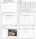
But then I thought, this woofer ported goes down to 33Hz. Why not have a ported synergy horn that has 1 or 2 of these woofers in it and have an all-in-one synergy horn? I did some modeling in WinISD of the woofer and what volume is ideal and how I would vent it, and settled on 60L box tuned for 33Hz. 2 ports, 6.8cm diameter @ 9.28cm long each. 1st port resonance will be at 1852Hz, and max air velocity will be 5.2m/s @ 33Hz.
Firstly, is that a good idea or a terrible one?
Secondly, do you think 1 of these drivers is enough? Or should I get two each for the left and right channels? I don't plan on listening at ear splitting volumes, but I also don't want to underbuild as well. If I get two for each horn then I will need 100L cabinets as well which is a bit larger.
Any thoughts will be welcome.
Thanks to anyone who shares their thoughts to help me.

Criteria for choosing the right L and C in second-order crossover

According to the resonance formula; Fc = 1/(2 x pi x sqrt(LC)), it’s clear that Fc depends on the product of L and C. So there are many combinations that yield the same product values. For example, 3.5mH and 100uF gives Fc of 270Hz, so does 4.0mH and 87uF combo.

However, assume Re of the driver is 4 Ohms in both combos, the difference is on Q of the filter. Consequently,

1) What is the criteria for choosing L, or C, for the initial step? That is, assume Re = (ideal) 4.0 Ohms, L = 3.5mH or 4.0mH for the first component.
2) With Re = 4.0 Ohms, the 3.5mH and 100uF produces Q = 0.676, while 4.0mH and 87uF produces Q = 0.590. Which one is more preferred?

I know the process should involve measurement, however, I also believe the calculation could be performed before measurement (for some people) as well.

Using a DAW (Digital Audio Workstation) as DSP?

Hello, lately I am tinkering with CamillaDSP on Linux Mint (latest kernel) and a Focusrite 8i6 usb interface, the software is very nice and I got it to run, but I do have problems to solve with Alsa and Pulseaudio, and the troubleshooting is very timeconsuming. So I was thinking if it would be possible to run and configure a DAW like ProTools (that I have installed) with plugins and a multichannel usb card? The entry ProTools is also free. I use ProTools for my homestudio and it works multichannel out of the box (Windows only, that is the sad part) and routing, eq, delay etc. should be no problem. Low latency, as much tracks (channels) as you want and your computer can handle. If you f.e. have a 4 channel output card you can route 4 tracks to those outputs. Inputs are also no problem, as the software is designed to actually record something and monitor the process of recording, and send audio to busses or other channels. So I do not see specific hurdles to configure a DAW as a DSP for use as a DSP crossover for an active speaker system. With a plethora of plugins available, you can create anything that is required. Any thoughts, someone already doing this? I am certainly planning to give it a try.

Please help with homemade C core inductor for CLC amp supply

Hello.
I am trying to make ironcore inductors from some old transformers. Some things are not clear to me:
Please check photos, where I marked areas of interest.
Photo 01:
01.jpg
1. Which parts can touch? (see picture). Can any off B's touch Frame A?
2. How many insulated gaps in core? One or two? Insulation between B3-B4 and B1-B2? or one insulated, one just glued?
3. If only one core gap needs is insulated, then I need make sure that another one is conductive? So i need to be careful so glue doesn't insulate that junction by accident?
__________________________________________________________________________________________________________________________________________________________________________________
Photo 02:
02.jpg

4. Can I build just one coil former, and wind all wire on it like shown in picture? Or do I need to wind two like original transformer, and connect in series?
5. If one coil is fine, D or H gap should be insulated? Or both?
6. Is there rough rule of thumb how much inductance I could get, knowing that this was normal 220V transformer. I probably should try winding some windings with random wire, and measuring inductance, since wire thickness should not make big difference in calculating?

1.5 or 2 inch round over for wide baffle?

I am going to round over the edges of an 18.75 inch wide baffle housing a Seos 15 and 15 inch woofer. Is a 1.5 inch round over sufficient? I’m concerned about the thickness at the corners if I go 2 inch. I was planning on a 1.5 inch thick baffle and 1.25 sides with a corner strip inside to make it thicker where I’m removing material. Moving to a 2 inch I would need 19.75” wide baffle.

Is there any benefit with 2 inch over 1.5? Can it hurt things?

The speaker is actively crossed.
I would prefer as narrow as possible for the baffle.
I require a round over for the grill type but can get away with 1 inch for that if there is no other benefit with 1.5 or 2 inch

Neurochrome Modulus-286: 65W (8Ω); 125W (4Ω) @ <-120dB THD Composite Amplifier Module

Neurochrome Modulus-286: 65W (8Ω); 125W (4Ω) @ <-120dB THD Composite Amplifier Module

Key features:
  • Mono construction.
  • 65/125 W into 8/4 Ω, respectively @ THD < -120 dBc.
  • Tested for stability with reactive loads up to 1.0 µF || 8 Ω.
  • Multi-tone IMD residual: < -100 dBV.
  • Damping factor: >560 @ 1 kHz; >225 @ 20 kHz (8 Ω).
  • Integrated noise (20 Hz - 20 kHz): 17 µV (A-weighted); 22 µV (unweighted) @ 20 dB gain.
  • Integrated noise (20 Hz - 20 kHz): 27 µV (A-weighted); 32 µV (unweighted) @ 26 dB gain.
  • Balanced input (can be connected to unbalanced sources as well).
  • Default gain: 26 dB for ease of use with other HiFi components. 20 dB available upon request. Higher gain possible by a simple resistor swap.
  • Four-layer PCB, fully optimized for the highest performance.
  • Designed, manufactured, and assembled in Canada. All components sourced from reputable distributors (Mouser, Digikey, et al.)
  • Available for pre-order within the next few days with a significant early adopter discount. Expected in stock by the end of November, 2018, at which point the into sale will end.
The Modulus-286 is a composite amplifier, which uses an LME49720 to perform error correction on two LM3886 power amplifier ICs in parallel. This results in an amplifier which has the precision of the LME49720 and the power of the two LM3886es. This error correction is the central point of the Neurochrome Modulus composite architecture. The composite design will correct for many types of error, including distortion and power supply induced errors. It is due to this architecture that the Modulus amplifiers achieve their high performance levels as evidenced by their ultra-low THD, IMD, multi-tone IMD, etc.

Note that attached picture and measurements are of the prototype. I will follow up with a more comprehensive set of measurements once the production version is in.
The production version will be Neurochrome Blue and professionally assembled in Calgary on a gold-plated PCB made in Ontario, Canada. The finished module will include aluminum mounting hardware (also made in Canada), which allows the module to be bolted directly onto a heat sink. This mounting method greatly simplifies the mechanical work for the the DIYer (only three holes needed with ±0.5 mm precision in their location).

Fully assembled modules are in stock and available for purchase here: Modulus-286: 125W power amplifier achieving -120dB (0.0001%) THD – Neurochrome

Enjoy.

Tom

Attachments

  • MOD286_PROTO.jpg
    MOD286_PROTO.jpg
    306.4 KB · Views: 2,789
  • Modulus-286 R2.0 PROTO_ THD+N vs Output Power (8 ohm, 1 kHz, 20 kHz BW).png
    Modulus-286 R2.0 PROTO_ THD+N vs Output Power (8 ohm, 1 kHz, 20 kHz BW).png
    50.8 KB · Views: 2,613
  • Modulus-286 R2.0 PROTO_ THD+N vs Output Power (4 ohm, 1 kHz, 20 kHz BW).PNG
    Modulus-286 R2.0 PROTO_ THD+N vs Output Power (4 ohm, 1 kHz, 20 kHz BW).PNG
    46.7 KB · Views: 2,583
  • Modulus-286 R2.0 PROTO_ THD+N vs Frequency (50 W, 8 ohm, 60 kHz BW).PNG
    Modulus-286 R2.0 PROTO_ THD+N vs Frequency (50 W, 8 ohm, 60 kHz BW).PNG
    35 KB · Views: 2,539
  • Modulus-286 R2.0 PROTO_ THD+N vs Frequency (100 W, 4 ohm, 60 kHz BW).PNG
    Modulus-286 R2.0 PROTO_ THD+N vs Frequency (100 W, 4 ohm, 60 kHz BW).PNG
    36 KB · Views: 2,547
  • Modulus-286 R2.0 PROTO_ THD+N vs Output Power (26 dB, 1 kHz, 8 ohm, 20 kHz BW).PNG
    Modulus-286 R2.0 PROTO_ THD+N vs Output Power (26 dB, 1 kHz, 8 ohm, 20 kHz BW).PNG
    51.1 KB · Views: 377
  • Modulus-286 R2.0 PROTO_ THD+N vs Output Power (26 dB, 1 kHz, 4 ohm, 20 kHz BW).PNG
    Modulus-286 R2.0 PROTO_ THD+N vs Output Power (26 dB, 1 kHz, 4 ohm, 20 kHz BW).PNG
    47 KB · Views: 454
  • Modulus-286 R2.0 PROTO_ Residual Hum & Noise (8 ohm, 1M FFT, 8 averages).PNG
    Modulus-286 R2.0 PROTO_ Residual Hum & Noise (8 ohm, 1M FFT, 8 averages).PNG
    50.9 KB · Views: 465
  • Modulus-286 R2.0 PROTO_ Muli-Tone IMD (AP 32-tone, 50 W, 8 ohm, 1M FFT, 8 averages).png
    Modulus-286 R2.0 PROTO_ Muli-Tone IMD (AP 32-tone, 50 W, 8 ohm, 1M FFT, 8 averages).png
    68.9 KB · Views: 476
  • Modulus-286_R2p0_DampingFactor.png
    Modulus-286_R2p0_DampingFactor.png
    61.8 KB · Views: 604
  • Like
Reactions: pbilous and barossi

Jhofland’s Diamond Buffer

Jhofland designed a nifty little diamond buffer that I got to try out for the past week. It works superbly and can drive 32ohm headphones with ease. It perfectly mates with a BTSB or a HyperSET hybrid tube buffer as the voltage gain stage. Jhofland had graciously allowed me to use his design and make it available as a preassembled ready to run run (RTR) board.

More info on HyperSET here:
https://www.diyaudio.com/community/threads/btsb-with-tube-buffer-hyperset-gb.396848/

Diamond buffer schematic:
IMG_5853.jpeg


PCBA render:
PCBA-render.png


Prototype under testing:
IMG_5803.jpeg


IMG_5802.jpeg


I’ll let Jhofland provide the particulars of the circuit but I do know it is Class AB and uses an LED to set the current sources. It’s an all BJT design and can take +/-12v to +/-20v (tested). Probably can go higher even.

Looking for proper subwoofer for EDM Wubzzz. Must have balanced output/input

I have been DJing since I was 16, I am now 27. I love listening to EDM music. I love the loud bass it produces. Bass music primarily. House music, dubstep, riddim sometimes. I also love rap, rock, orchestras music.

I have KRK Rokit 5s. Looking for something to pair it up with. Focusrite Scarlet solo the newest version I think so it has balanced output. Thing is, I used to have and SVS subwoofer the 10 inch one but it didnt have balanced outputs, so im looking for one specifically with balanced outputs to match with my scarlet solo and my KRKs.

Main Questions:
1. Should I just get the KRK subwoofer to match with the KRK studio monitors, or is it worth finding another sub to get more punch out of the bass? is there a better bang for my buck?
2. What subwoofer do you personally have that you love? Do you listen to EDM music? Looking for something dope, I just found this site.
3. Thats really it. I have a scarlet solo into my computer that used to go into my subwoofer then into my studio monitors, but now i need a balanced subwoofer.

Hope this was ok to post. I see a lot of ppl building their own speakers and im not there yet, but would be down to learn, I like building computers. Thank you

Never Too Late

Ages of reading & silent following.
I'm not that super hi-fi clean guy, coming from a production rehearsal & guitar tube amp background climate. Probably more close to old dirty repairman / player side than listener, but I owe a lot to this place.
Old member of other audio, valve amp, diy places out there.
I know there are some well known old dogs here, who have helped me through other forums in the past. Will always be honoured to them. They know who they're.

Salute everyone. 🙏

Much love & greetings from Greece.
  • Like
Reactions: stv

6BM8 "tiny tube amp" build + Video Series

I decided to make a video series of my next project, a small 6BM8 SE UL scratch built amp that is perfect for a beginner or anyone looking for a fun project to build. You should be able to get all the parts new for under $300, it's a simple design and from what I have read, these are great sounding tubes.

I plan to post a final schematic and a BOM once I finish the amp and get everything sorted out. I am explaining in fine detail my thought process, tips on chassis fab work etc. so anyone with basic tools and are good with their hands should be able to build one. I also plan to show how to test it on a scope and the process I use for tweaking different things to get the best sound out of it.

I have warned folks, if you think you might want to build this with the 10W 5K Edcor UL output transformers I am using, you might want to order them now. It's taking 8-10 weeks to get these. The rest of the parts are pretty easy to find.

Anyway, I wanted to share it here. I'm about half way done, all the fab work is finished and the layout decided on, just waiting on a few parts to finish wiring it all up. Hope you enjoy following along as I build it.

6BM8 DIY Stereo Tube Amplifier Series - YouTube

Attachments

  • 6bm8.jpg
    6bm8.jpg
    299.8 KB · Views: 1,371

For Sale Large vertical Heasinks (6) for Krell or Mark Levinson Class-A style amps

FS, Large vertical Heasinks (6) for Krell or Mark Levinson Class-A style amps, used with TO/3 drilling. Great Heasinks for your Class-A project, see pictures for details.
Each heatsink weights 1.4kG. Can also accept TO-220 or TO-264 parts with a little work, that's DIY after all. Was aving them for a Krell KSA-50 project that I have to let go.

Asking 50U$ + shipping.

Payment with Paypal (3.5% fee) or EMT bank transfer within Canada

Thanks for looking
SB

Attachments

  • 20250209_105625.jpg
    20250209_105625.jpg
    348.6 KB · Views: 164
  • 20250209_105653.jpg
    20250209_105653.jpg
    268 KB · Views: 155
  • 20250209_105706.jpg
    20250209_105706.jpg
    221.8 KB · Views: 146
  • 20250209_105711.jpg
    20250209_105711.jpg
    210.4 KB · Views: 167

For Sale Vacuum State Electronics RTP3D, upgraded from an original RTP3C kit

SOLD

Asking $3800 $2000 plus USA shipping. Will only ship to USA

I will start with a caveat. I believe the person purchasing this preamplifier needs to have the ability and interest to SAFELY work within a tube audio product with 360vdc power as checking the output of the Superregs and power supplies is a likely need. I consider this preamplifier to be like a high performance car, in that familiarity and upkeep are a necessary part of ownership. This is not a typical plug and play audio component.

When last available the kit form of this preamp was well north of $10,000, and the factory built unit was $25,000.

Vacuum State RTP3D, which started life as a RTP3C kit I purchased from Allen back in the day. This is a differential line stage and MM/MC phono stage preamplifier. I later purchased the RTP3D update CD and buffer board information from VacuumState, built the choke loaded power supply in 2020, got it in a newer, less ratty chassis then the 3C power supply came in, and at the beginning of 2022 rebuilt the signal chassis with some silver wire, some copper wire, all new resistors, all new matched phono board components, SM2210, and a change of regulators for the -24 volt supplies to very quiet and very stable LDO regulators using the AMB.com boards. All new components except the film caps were put in the SuperReg boards also. I designed and installed a new signal chassis back plate with only rca (audio note silver plated) and XLR (neutrik) jacks. The unit has Elna source switches and DACT stepped mono attenuators.

The unit has seen little use since then as I got out of vinyl just after that. About 100 hours maximum.

Gain of the preamplifier section can be changed from about 40db to 0db by soldering in a couple resistors, and the gain of the phono sections can be changed in a similar fashion. Presently gain is set at 10dB for the line stage and 45 dB for the phono section.

Included tubes are eastern euro PCC88 tubes, the amp filament regulators are set to run at 300mA each for these series heaters. The filament regulators are set for 6922/ECC88/PCC88 type tubes, not 6DJ8 that have a different filament current need.

I just did some cursory testing of the unit again, and all is well. I was going to make new superreg boards, but never got around to it. The superregs run HOT, and I kept the shunt current to about 10mA to put less heat into the shunt components, and to my failing ears, sounds no different than the spec’d 15 mA shunt current.

The sale includes the pictured power supply and signal chassis, the original RTP3C, RTP3D, and buffer board information / pdfs on CDs, some extra silver wire if you wish to go that route, and I will send you some pdf links to updates on the RTP3D schematics that correct some inconsistencies in the VS documentation. I will include a printout of the Superreg documentation…it is marked up. I will NOT sell the build info from VaccumState separate from the preamp. It is their IP.

Weight of the signal chassis and power supply is over 40lbs combined.

USA shipping and sale only. I plan to package as carefully as possible with rigid foam around all sides of each component.

Shipping would be in a 20 x 20 x 12 box, about 50 pounds.

Contact me here if you have additional questions or want some more specific information.

IMG_0209.JPGIMG_0212.JPGIMG_0213.JPGIMG_0214.JPGIMG_0631.jpegIMG_0633.jpegIMG_0643.jpegIMG_0646.jpegIMG_1705.jpegIMG_1707.jpeg

Do I need capacitors in a passive audio switching circuit?

Hi,
I'm trying to build a 3 channel audio switcher. 3x 3.5mm inputs and 2x 3.5mm outputs one for headpones and one for speakers. I'm using DPDT relays to switch channels. I've added 2 digital potentiometers for volume control, which is controlled by a Pico and Rotary encoder. Because I'm using DC components (DigiPots and Relays), do I need to add blocking capacitors before each of those components?

Another forum mentioned this: "If you use an electrolytic, I recommend a bi-polar type between 10uf and 22uf." (https://modwiggler.com/forum/viewtopic.php?t=171691)
So I was planning on whacking a few 10uf bipolar electrolytic caps in the circuit, but I'm not sure if this is even necessary...

I've attached my current schematic (not including all the digital control circuits, just components directly in the audio path).

Any help would be greatly appreciated! 😀

Attachments

  • Screenshot 2025-02-14 101514.png
    Screenshot 2025-02-14 101514.png
    167.2 KB · Views: 57
  • 476744609_1140135664473201_3876514953701226331_n.jpg
    476744609_1140135664473201_3876514953701226331_n.jpg
    514.9 KB · Views: 47
  • 476874678_3883562171920989_3756589885135429905_n.jpg
    476874678_3883562171920989_3756589885135429905_n.jpg
    488.5 KB · Views: 48

6S41S Single-Ended Amplifier

I'm contemplating doing a single-ended amplifier using the 6S41S triode, perhaps with a depletion-mode mosfet front end. I'm thinking of using the Toroidy 600 ohm primary toroidal single-ended iron for the output, and a discrete shunt regulator to bias the cathode (damped/bypassed by a capacitor of suitable voltage rating). I would run the front stage off the output of a Plitron medical isolation transformer I have a couple of, and the 200V for the output stage would be generated with a discrete self-driven buck regulator with suitable filtering. I need to rummage around and actually find my 6S41S stash, and I think I have a couple of suitable sockets (the tube is a little weird, and takes a strange 7-pin socket).
  • Like
Reactions: astouffer

Juicy Music Blueberry Preamp - Tech Info?

I just received a Juicy Music Blueberry Xtreme with Cream preamp recently. I originally owned it from 2007-2018, sold it, and just bought it back. It was "one that got away".

I opened it up to put tubes in and see that 2 traces to the rectifier bridge are lifting. The PCB looks like it took a lot of heat in the area of that bridge. The caps around the bridge also look to be cracked / drying out. Before I power it up I want to fix that up.

While I was waiting for the shipment I wanted to see about any mods or if technical details are out there on this preamp. I found out that Mark Deenen (designer/builder) offered a few mods that I'd like to implement: power supply mod, maxim mods, and 6H30 retrofit. Mark is long out of the business now. I tried using an email address I found for Mark D, but it bounced. I tried a call and email to Craig at NOS Valves. No response.

Does anyone have schematics for this one?? Does anyone have this preamp with those mods who would be willing to take a few close up pictures of the boards so I can compare things?

My plan is to simply put a bridge rectifier with a snubber circuit on the chassis and run wires where they need to go. That's an easy fix for the obvious issue, and it solves my short term need. I'll need more info to jump into the other mods.

Attachments

  • Juicy Blueberry-01.jpg
    Juicy Blueberry-01.jpg
    765.2 KB · Views: 153
  • Juicy Blueberry-02.jpg
    Juicy Blueberry-02.jpg
    621.3 KB · Views: 154

Tinsel lead repair - advice sought

I have a driver that needs fixed, an Usher midwoofer from an S520. One of the tinsel leads has come adrift from the voice coil lead-out wire. Here's a picture:
20250102_120013.jpg


The voice coil lead-out wire is glued to the cone, which is clear plastic of some sort. I plan to use a scalpel to scrape the lead-out wire to expose a little more copper, and also to lift the end of it clear of the cone, before attempting to solder the tinsel lead back onto it.

The tinsel lead has a big blob of yellowish glue on the end, which was supposed to hold it in place. That'll need to be removed, and when I've resoldered the wires together, I'll need to glue the joint down onto the cone with a fresh blob.

Have I got all that correct? Any advice? What type of glue would be best for regluing the joint to the cone?

Adding a tweeter control to an existing Crossover

I have this idea of adding either heavy duty pot to a crossover for the adjustment of a tweeter in a crossover or at least a switch that would adjust tweeter level. The tweeter is 10 DB more efficient than the woofer so I am betting that there could be some latitude here. As it sits now, the tweeter is padded down by 10 DB. It is a 2-way crossover with a 2nd order Butterworth slope at 2.5 Khz. The woofer is a Mark Audio 12PW used in a loaded horn design, and the tweeter is a Scan Speak horn loaded tweeter. I will have to look at the model number. I bought it from Madisound for about $42 ea.
I would actually like to tip up the tweeter level just because it might help me and my old ears but then maybe a bad idea. You guys will certainly have valuable advice. Thanks.

Converting obsolete AV receiver to powerful class A amp?

Top of the line yesterday receivers (without, or with broken hdmi inputs) are going to the recycling every day. This is really sad, given their huge, no longer produced power supplies, and their massive heatsinks. So much potential. I just cannot watch these being recycled or trashed. Just unethical waste. Example:

1738798624428.png


So I started buying them left and right, for 1/100 of their original cost. Been gutting them and putting cheap chinese amp PCB in there with impressive results.

But then I started thinking: These also came in some cases with elaborate amps, and real, first quality output transistors that simple cannot be bought on the chinese web sites. Then came the crazy ideeyer of using all those resources to build class A amplifiers? Some of them have state of the art input stages in their amplifier, even resembling the well known "blameless" topology. Their ouput transistors are guaranteed not to be chinese knock-offs. And their heatsinks are huge.

I want to try to convert one these amps to class A.

Shields down please and no "it can't be done", "they're not designed for that", etc... Hope are not made to be shattered.

Case in point: In the following class AB schematic, the input stages are perfectly fine.
1738798992597.png
I am seeking advice on how to take away and rewire one half of the output stages to change the (probably positive) side to a current source, possibly involving redesigning what is inside the red circle.

Please, let us waste anyone's time with how it cannot be done. I am seeking amplifier design advice on how to go about it with the least chances of failures.

And yes, I am aware of the voltage, current and power dissipitations issues. I will consider them off-topic. I am seeking help about the topology of the circuit, nothing else.

Thank you!

Attachments

  • 1738798753587.png
    1738798753587.png
    75.1 KB · Views: 88
  • 1738798915196.png
    1738798915196.png
    107.5 KB · Views: 86

Power stage impedance

Newbie question I guess, but I searched the forum and found no fitting answer.
Suppose I want to control the behavior of the power input stage used with a class D amplifier (in my specific case I'm planning to use a MA12070p).
What can I assume the impedance load will be?
Knowing that, I could dimension a R-C network for, for example, set up a soft start.
One could argue that since you want most of the power to go to the speakers, you can assume that this is the main load. However, there is also a charge pump in the middle, among other amenities, and it all seems beyond my current understanding of (this kind of) electronics.

A good budget combo

Here's a simple 2 way I just put together out of parts from my stash. A 2 way, Woofer is Wavecor WF160WA02, a well behaved good sounding driver, NLA, but its Round Frame version the WF168WA01 (identical specs) is available in Aus for $75. Tweeter is SB21SDC-C000-4, (~AUD60, I bought these a few years ago, so paid a bit less) nice dispersion chracteristics.
Simple xover at ~ 1750Hz, .27mH on the woofer to smooth out its top end, 12uf & .68mH 2nd order on the tweeter. Box repurposed from a previous project, 29L tuned to the mid 40s gives a slight bass lift. No BSC but doesn't seem to need it, if I need more lows I can always turn on my dedicated woofer boxes.

Attachments

  • WavSB.JPG
    WavSB.JPG
    291.6 KB · Views: 72

Subwoofer cabinet design construction and testing

Hi ! i am here after coming to a very important conclusion
The subwoofer duty is the most challenging application for a cabinet (too trivial ? 😉)
Let me elaborate a little first
Above a certain frequency the vibrations level is so low that taming them is not a big issue
I would fix the cut at about 200Hz more or less
For this reason my ideal speaker has the bass box separated by the other drivers
The range up to 200Hz is very well within the limits of any kind of sub even the biggest ones And that is what i would like to do in the future
A satellite dealing with the range from 200Hz up above a sub with some kind of mechanical decoupling
This said i would like to hear what kind of test do you perform on your subwoofer cabinets
In particular my main interest is to understand what kind of measurements could provide the most reliable information about the quality of the design and construction of a cabinet for a subwoofer
I mean you can brace and add mass to the cabinet
But how do you know when the cabinet is well done ?
Then i would like to suggest a very weird test to get an idea of the vibrations of a cabinet side
Just stick with some biadesive tape a small piece of mirror on the side and direct a laser beam on it from an angle
The movements of the mirrored point will provide a measure of the vibration of the cabinet side
In the ideal case the point should stay steady without any kind of oscillations
Of course the front baffle is the most critical side As always for speakers in general
Thank you very much indeed
Kind regards, gino

Seeking advice for a mini 3-way speaker (Woofers!!)

Hello,

I acquired a pair BlieSMa M74S-6 for a great price. The seller was upgrading their MUM-8 to the beryllium version of the dome midrange. I got very lucky!!
Let's pair the M74S-6 with the T25S-6 and plan on a passive crossover design to start. I don't want to go active quite yet.

What I would love help with is finding a 5" (or possibly a 6" or even dual 4") driver to build a compact 3-way?
From HiFiCompass' study of the M74 product line, I am assuming the high-pass will have to be near 500Hz.
I would like to keep the enclosure for the driver under 0.35 cu. ft. (10 liters).
Not sure I can ask for much in the way of sensitivity here. Getting close to 90db 2.83v/1m would be the dream.
Shooting for an F3 in the mid 60Hz range and F6 in the 50Hz range, if possible.
I am down to mounting the BlieSMa drivers on a flat panel akin to the LX521.4 or building them into an enclosure like the Barefoot Sound Footprint 01 where the woofers are locating on the side of the cabinet.


Here are a couple of options I have found.
Anarchy-554
SB Acoustics SB15NRX2C30-4

Currently, the mini 2-ways I am using contain a T25A-6 along with a Purifi PTT4.0X04-NAC-03 and utilizing a 6" Purifi PR. Loving these speakers!
They are flanked by a small subwoofer.

Fun thoughts on this one?!

For Sale Ryan D3 TDA1541 DAC

Fully built and tested Ryan's D3 TDA1541 dac on sale using high quality parts. I will include a Miro 1541 psu board if anyone wants to use that to power the D3. Too many dacs in my line-up so these need to make place for other builds. I am using a Aya 5 with the same TDA chip in my main setup as well as Soekris R2R dacs / AD1862 dac in my second setup.

More information about this dac here - https://www.diyaudio.com/community/threads/diy-tda1541a-pcb-d3.328060/

Asking $400 including psu board and free shipping within CONUS.

1734540832669.jpeg


1734540851293.jpeg


1734541124909.jpeg

This must be the place ...

Hello all! After many google searches for particular gear issues, one thing was consistent - people on DIYAudio were discussing (and solving) the issues and modifications that interest me. I work at a small used record/cd/tape shop that also sells vintage stereo gear: mostly Marantz, Pioneer, Klipsch, Technics, Sansui, Carver, etc. Receivers, integrated amps, separates, speakers, turntables. At home, I'm currently running a McIntosh C29 + MC2105 feeding a pair of Dahlquist DQ-20's. Mostly listen to records on my Technics SL-120mk2 with a Nagoaka MP-200 cart > Parks Audio Budgie tube phono stage. Streaming digital through a Wiim Mini > Schiit Audio Modius DAC. Always interested in reading discussions on gear, repairs and modifications. Looking forward to learning more and participating in the discussions. Thanks!

Hello! Thank you for accepting me!

Hi everyone reading this! My english is not my first language so misspelling or bad texting is something you shouldnt consider!
I recently bought some old PA from a small pub which went close, and wanted to experiment with the drivers from the existing boxes ! As far as i testet everything works and they are jrx series from jbl! There are to jrx215 and two subs jrx218s! I bought the boxes just to get the drivers and build (experiment) with new cabinets and design! Ive been always intrigued from augspurger loudspeakers and wanted to imitate them at this point! Im looking for some blue prints on dimensions and building hierarchy! Thnx in advance

Attachments

  • IMG_1586.jpeg
    IMG_1586.jpeg
    141.2 KB · Views: 29

SMPS auxiliary design/startup

Hi everyone, just finished my DC-DC amp SMPS project, now i would like to have a go at building an AC to DC SMPS. I will again be using the TL494, driving a half bridge via a gate drive transformer.

The only part of my understanding that im struggling with, is providing 12v auxilary power to the tl494 at startup. I understand that at startup you need to (somehow?) pull up one of the half bridge transistors base, in order to energise the primary and in turn, the auxilary winding.

Surely, one pulse on the auxilary wont be enough to get the tl494 going, also considering that the GDT requires a little current, its difficult?

Also, if the tl494 does manage to startup, i assume that you need to really quickly disable the inital pullup on the chosen half bridge transistor, to avoid shoot-through. Also, if the chosen startup transistor is on for too long, could it not leave saturation issues for when the tl494 kicks in, even with soft start.

At the moment, im considering the option of adding a very small, simplistic self oscillating 12v smps (similar to the sort of smps you might find in a phone charger brick) to the tl494 control board so that it can have its own supply, removing the need for the main transformer to have any auxilary winding, and removing the complication of initial transistor pullup on the half bridge. Would love to hear some relatively simple auxillary ideas 😁.

Samuel Groner's super opamp

In 2017 Samuel Groner, with Martin Polak, published a new composite opamp design: Journal of the Audio Engineering Society ENGINEERING REPORTS, Vol. 65, No. 5, May 2017: Low-Distortion, Low-Noise Composite Operational Amplifier.

Late last year I was looking for a very low distortion opamp and thought I'd give this a try. I laid out a small adapter PCB for a DIL08 foortprint, see pics. The result was all I expected, an opamp with distortion specs literally out of this world. I was not able to verify the claimed THD < 180dB (yes you read that correctly) but got numers at -160dB and better.
I'll post measurements in my next post.

Anybody here build this as well, experiences?

Jan

Attachments

  • groner composite opamp.PNG
    groner composite opamp.PNG
    14.5 KB · Views: 4,698
  • 20190506_093359.jpg
    20190506_093359.jpg
    262.5 KB · Views: 4,355
  • 20190506_095319.jpg
    20190506_095319.jpg
    262.9 KB · Views: 4,264

Looking for Valley People QLZ schematic

I have been gifted an old Valley People QLZ quad microphone preamp (picture attached).
I recall when these came out (1980's) and were novel for having a low input voltage noise without using a transformer. I'm looking for a schematic of the entire unit. I'm thinking of restoring and perhaps modifying the preamp and a schematic would be very useful in that process. I am confident that I could trace out the schematic where standard op-amps are used. I might have found a pinout of the Valley People modules and perhaps that will be enough information to trace out the remainder of the schematic. But if anyone knows where to find a full schematic, please let me know; it will save a lot of work.

Thanks,

Tom

Attachments

  • qlz_1.jpg
    qlz_1.jpg
    34.2 KB · Views: 32

Powering Raspberry Pi from Bose SoundDock Portable via 30-pin connector

I'm trying to build a whole home audio system by upgrading my existing speakers, I don't want to throw away perfectly good equipment, and then have to pay Sonos or others a big chunk of change.

So to that end, I have already built a Raspberry Pi ShairPlay device using a RPi Zero and an Audio Shim DAC. It works very well but the external cable and 3.5mm audio jack cables are annoying when I plug it into my Bose Sound Dock. This got me thinking I just need to get a female 30 pin iPod connector, read up on the pinouts, do some soldering and hey presto my old Bose is back in business as a 'Smart' speaker.
IMG_5824.jpeg


I tried to buy a 30 pin connector on line but the merchant was not too helpful and alternatives are few-and-far between, also it was too expensive, so I went on-line and purchased a cheapo weird 30 pin to USB A female lead and proceeded to tear it apart. Here it is after I did some desoldering:

IMG_5823.jpeg


Just like the 30 pin connector itself pinout information is not really out there (come on its Apple right) so I have tried a few things but no success. I need 5v for the RPi to power up, but I have never got this from the Bose. I think there is some kind of hand shaking that has to happen so that the device announces to the Bose what it is and then Bose responds accordingly. The reason for thinking this is that I probed every combination of pin combinations and could only ever find 1.7v

Summary:

Confirmed the iPod Dock works with an original iPod

Analysed original USB cable connections before I tore it apart:
  • Red (USB 5V) → iPod Pin 23
  • Black (GND) → iPod Pin 16
  • Grey (??) -> iPod Pin 24
  • Green (??) -> iPod Pin 27
Current best response from dock with:
  • Pin 11 → RPi GND (Audio Switch)
  • Pins 15/16 → RPi GND
  • Pin 27 → 1kΩ resistor to RPi GND
  • Pin 23 → RPi 5V
Results in: Orange flash → Solid green → LED off on the Sound Dock. Looked like it was negotiating with something


I looked around this forum and others but didn't find anything directly helpful, but I hope that someone might be able to point me in the right direction.

Thanks

Wellco
Projects by fanatics, for fanatics
Get answers and advice for everyone wanting to learn the art of audio.
Join the Community
507,675
Members
7,883,704
Messages

Filter

Forum Statistics

Threads
406,003
Messages
7,883,704
Members
507,675
Latest member
crnmddoc