Sizing PT and rectifiers
- By deafen
- Power Supplies
- 4 Replies
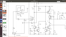
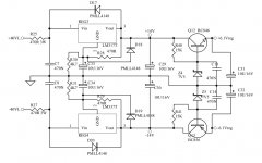
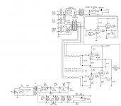
I'm using bench supplies to prototype an amp design, and I'm about ready to move on to the power supply. Plan is 400V B+, 350V drivers, and 250V screens. B+ and screens will each have a simple MOSFET-based series regulator with their own VR tubes for voltage reference, and the driver supply will pull from the B+ with an RC filter. The PT will be set up as full-wave, with a zener string in the center tap connection for bias supply.
I've verified these current draws using an inline ammeter set for DC amps:
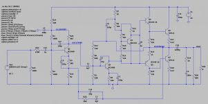
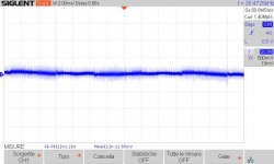
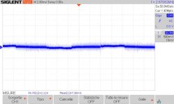
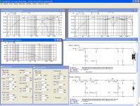
When I modeled it out in LTspice, RMS current at each rectifier diode was over 400 mA. So, questions:
Thanks!
I've verified these current draws using an inline ammeter set for DC amps:
- 160 mA plates
- 35 mA screens
- 10 mA drivers
When I modeled it out in LTspice, RMS current at each rectifier diode was over 400 mA. So, questions:
- Which current figure is the correct one for sizing the transformer? IOW, is a transformer like the Antek AS-3T350, rated for 400mA per HV winding, sufficient?
- Which current figure is the correct one for sizing the rectifiers? I'm looking at using a pair of 6DM4A, a diode rated at 200mA continuous.
Thanks!