FS: Wynpalmer's OPA1656 and LMH6321 High Perf Amplifier
- By patchoncas
- Swap Meet
- 7 Replies
FS: (Price Drop) Wynpalmer's OPA1656 and LMH6321 High Perf Amplifier
Hello,
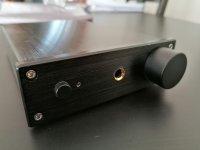
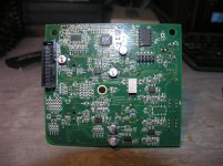
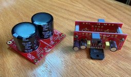
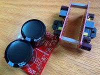
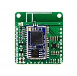
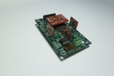
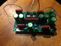
I'm selling a fully built, ready to plug in, turn on and enjoy version of Wynpalmer's low cost, high performance amp using OP1656 and LMH6321.
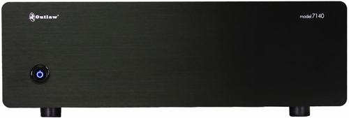
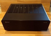
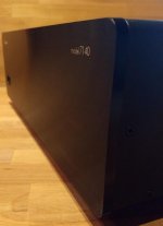
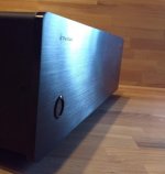
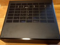
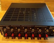
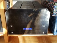
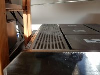
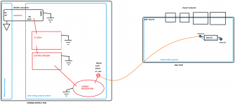
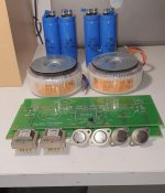
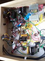
This amp was built to spec, following Wynpalmer's BOM and is powered by a Silent Switcher, an excellent power supply with practically nonexistent noise created by Jan Didden. It is housed in a full aluminum enclosure which has a similar width as an O2, but with a bit more depth. Selling it due to lack of use (was my office amp, but changed office; it's also a good opportunity to invest in more DIY)
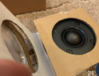
Features include an attenuator for volume control with 21 steps that uses 1% SMD resistors, one set of inputs, two sets of outputs (headphone and preamp out), a power button and a nice white LED for power indicator.
The theme here was aiming for simple, yet high performance. 🙂
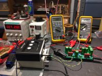
Specs are:
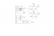
(PSU)
9V 2A power supply that feeds into the Silent Switcher
4.7uV output noise
More at:
The SilentSwitcher | Linear Audio NL
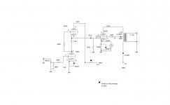
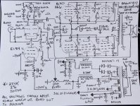
(Amp)
Peak output drive current set at 270mA/channel
0.4W max into 15 ohms.
0.8W max into 30 ohms.
0.15W max into 300 ohms.
6dB gain.
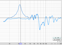
THD+N @1kHz, 2v RMS output 80kHz measurement bandwidth: <-114dBc (0.0002%) A weighted.
More at:
Low cost, high performance headphone amp using OPA1656 and LMH6321
I am asking for 150€ plus shipping.
You can find more photos at the following link:
Imgur: The magic of the Internet
Hello,
I'm selling a fully built, ready to plug in, turn on and enjoy version of Wynpalmer's low cost, high performance amp using OP1656 and LMH6321.
This amp was built to spec, following Wynpalmer's BOM and is powered by a Silent Switcher, an excellent power supply with practically nonexistent noise created by Jan Didden. It is housed in a full aluminum enclosure which has a similar width as an O2, but with a bit more depth. Selling it due to lack of use (was my office amp, but changed office; it's also a good opportunity to invest in more DIY)
Features include an attenuator for volume control with 21 steps that uses 1% SMD resistors, one set of inputs, two sets of outputs (headphone and preamp out), a power button and a nice white LED for power indicator.
The theme here was aiming for simple, yet high performance. 🙂
Specs are:
(PSU)
9V 2A power supply that feeds into the Silent Switcher
4.7uV output noise
More at:
The SilentSwitcher | Linear Audio NL
(Amp)
Peak output drive current set at 270mA/channel
0.4W max into 15 ohms.
0.8W max into 30 ohms.
0.15W max into 300 ohms.
6dB gain.
THD+N @1kHz, 2v RMS output 80kHz measurement bandwidth: <-114dBc (0.0002%) A weighted.
More at:
Low cost, high performance headphone amp using OPA1656 and LMH6321
I am asking for 150€ plus shipping.
You can find more photos at the following link:
Imgur: The magic of the Internet


