• Locked
FS: Open Baffle Speakers Kit

SOLD: Open Baffle Speakers Kit

Hi. Seeling this for a late friend, so not much more info. Looking to get 200$CAN, or 160U$ + Shipping and 3.5% Paypal fee

Was thinking to post an Ads on Canuck Audio Mart (US AUdio Mart as well), but I thought to post on our forum first.

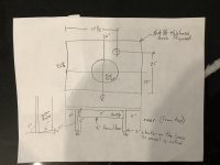
Very complete kit to build a nice little Open Baffle Speaker project, just add the plywood (enclosure drawing included) and you're ready to go. All parts are brand new, never used, just open to take picture.

The kit includes:
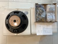
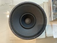
-2x Full range 12'' driver 'Hammer Dynamic', 8 ohms
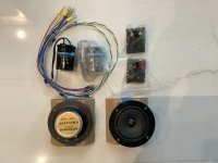
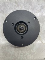
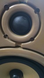
-2x Super Tweeter 'Big-Air Acoustics', 8 ohms
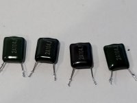
-2c 2uF Obligato Coupling caps for the tweeters
-Wire harness, looking like good quality TFE hook-up wire, possibly Cardas and binding posts.

As I said I got the complete kit, but not much more, see the pictures for details...

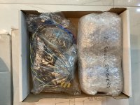
I have the original boxes for the woofers, and the rest is already packed, ready to ship.

If interested let me know. Thanks for looking
SB

Attachments

  • IMG_2722.jpg
    IMG_2722.jpg
    441.9 KB · Views: 552
  • IMG_2723.jpg
    IMG_2723.jpg
    437.7 KB · Views: 535
  • IMG_2724.jpg
    IMG_2724.jpg
    982.4 KB · Views: 551
  • IMG_2725.jpg
    IMG_2725.jpg
    421.5 KB · Views: 518
  • IMG_2726.jpg
    IMG_2726.jpg
    382.2 KB · Views: 512

Parts Alert!

I often go to a massive surplus store in Burbank California. They have deep stock of typical NOS power amp transformers like 24-36vct at 4 amps as just one example at fantastic prices.

And they also have a large stock of computer grade screw terminal capacitors. I find these obsolete in current parts supplier catalogs or very expensive.

Just FYI for those in the area and they might do mail orders as well, I don't know but they are active on Ebay.

APEX I Home

BTW, need surplus jet engine parts? They have those too! (There was a lot of military and aerospace industry in the area up until the late 1980s)

AMT Pro-4 as OB tweeter

I made some measurements of AmtPro-4 with open back, and add small horn in front of it in form of beams with cross section 20x27 cut under 45 degree towards diaphragm.
11 kHz big bump is EQed out -8 dB, rest is not filtered.
Measurement made with REW and converted to polar plot with VituxCAD.

Did it make sense to use AmtPro-4 as OB tweeter? Plan is to had high pass filter at about 1 kHz.
Did horn in front of it give any advantage or pure AmtPro-4 is better?
Upper plot on image is with horn, lower is pure AmtPro-4 OB.
I added also power and DI plots, upper is with horn.

Attachments

  • OBTWPolarPlot.jpg
    OBTWPolarPlot.jpg
    169.7 KB · Views: 688
  • OBTWPowerDI.PNG
    OBTWPowerDI.PNG
    160 KB · Views: 676

Making 3 front channels out of stereo signal

Hi there,

I'd like to start a new thread about 3 front channels. I know there have already been some discussions about this in other threads, but they were mixed by many other issues and somewhat distracted.

I'm no expert in Psychoacoustics and there're lots of talks (and debates) around, I'd rather not repeat. In my simpliest thoughts, 3 front channels should be an upgrade to ordinary stereo by an important supplement in the center. And practically there's far less hassle to implement compared to full surround mult-channel (5.1 or 7.1, or whatever).

But how?

The trinaural processor mentioned in this is probably the most elaborated I've seen:
http://www.diyaudio.com/forums/multi-way/36254-try-ambiophonics-your-speakers-40.html#post2520370

However, this processor is not cheap. And it seems the circuit is quite complex. If it has to be that complex, I'd rather put it in digital. (OK, that's me.)

Ideally, I think 3 front channels should be:

true L ..... true C ..... true R

But how to get these 3 channels from stereo signal?


OTOH, there're also other proposals, such as:

L .... (L+R) ..... R

or

L-R ..... (L+R) ..... R-L

These two can be easily done in analog circuits, even between amp and speakers. Supposedly they also provide some good features to please those who are using them. ( No? )

I've briefly tried the last one. The experiement is still on going and the setup is probably far from ideal. Also, my (subjective) observation is still too preliminary to talk about. (Very interesting, though...)

So, I'd like to hear your opinions.

Thanks in advance. 🙂

Another day, another idiot trying to build a BP4

Another day, another idiot building a BP4

First post and of course, asking for help. I've done a ton of reading and I think I'm on the right track but really would like some sanity checking. The wife has a Can Am Defender (Side by Side) and wants some "boom boom". It's an open model and I'm putting the box in the bed so no cab. I'm pairing the subs with a set of wake tower speakers that come in around 60 Hz.

What I'm using:

TS Params:
W12K9D2-TS.png


I used these formulas to back my way into the following specifications:
  • fL 32.40750349
  • S 0.6
  • fH 74.74941047
  • Qts 0.86
  • Front Chamber 1.3968 (per sub, separate chambers)
  • Fs 38.09
  • Rear Chamber 1.448182937 (per) 2.896365875 (shared)
  • fL Factor 0.7317
  • Tune 49.22025233
  • fH Factor 1.6877
  • VAS 0.97
  • Qbp 1.1113

Putting all of that into WinISD and then adjusting the port to somewhat reasonable air velocity got me here:

bp4-transfer.png

bp4-velocity.png


The above is modeling a single driver so when I build I'll double the diameter of the port thinking being it's two subs and WinISD is modeling one driver.

That brings me to the box design.
bp4-interior.png

bp4-exterior.png


The box is 51" wide by 20.50" tall by 20" deep (front to rear). The port total width is 49.5" by 2" tall (inside dimensions) and 11.72" long.

Where I'm starting to struggle is first, is all of this in the right direction or have I gone badly wrong somewhere?

Second, I know port volume is not included in box volume, but if I change my port length to tune then the box volume will change which changes the port length which changes the volume, etc. Any tips? Or have I designed the port incorrectly by being above the speakers?

Should I redesign the box completely and fire sideway? Move the port? Should I just surrender and go back to IT a failure in the audio world?

Need help please, wharfedale diamond 8.2 tweeter damaged

Hi,
I received old Wharfedale diamond 8.2 speakers for expermenting with bi-amping, but its tweeter got damaged in transit. The front grill broke off and its plastic parts punctured one of the 1" silk dome tweeter. I played it on a moderate levels and whatever high frequency sound it was giving out during initial stages of 30min playback has now gone totally silent. I checked all connections / terminals from the backside ,visually they all seem ok. I got quoted from its authorized distributer Designer Audio , Mumbai, India about 48$ per pcs + shipping, which is way beyond my budget and result in an improper mismatch between old and new tweeters

So I have thought of few options-

1 Repair it locally, but I don't think that will make it sound like the originals

2 Replace it with cheaper options like I-Copper i-T257 Silk Dome Tweeters 11$/pair used in car audio. Not so sure about external size and fitting to match the current enclosure space. Currently, other well known budget brands are out of stock on Amazon India. My budget is around 10-15$

3 Maybe get a spare tweeter with same specs from flea market.
I'm open to all kinds of suggestions.

I live in Mumbai city , so I can buy it from local market too if shipping costs are prohibitive, provided I have some advance knowledge about good budget brands.

I have not yet opened the speaker box to check the insides, I have basic knowledge of DIY repairs and basic tools to do the job. I have no golden ears and prefer OEM brands, but they should sound somewhat like the originals. My assumption is they are 6 ohms tweeter , Sensitivity 86 dB as per information available on the web. Since bi-amping is my objective , little deviation from original specs is also ok with ne. Please correct me if I'm wrong.

Thanks.

Attachments

  • front.jpeg
    front.jpeg
    78.4 KB · Views: 128

Sonosub Driver Selection Help

I am trying to make a ported sonosub (likely with 24" diameter sonotube). I am looking for drivers that extend sub 20hz without room gain as my home audio setup is very suboptimal (split level open floorplan with >40 foot longest dimension).

I found a few promising subwoofers <$250, <400 liter box. A promising candidate is the DCS380 (in 377-liter box can get 108 dB with -3db at 17.8hz, and the MX15-22 which does more with an enclosure half the size but it is sold out. UM12-22 UM15-22 MX12-22 also all promising.

Any driver suggestions? I seem to be stuck in Dayton Audio land.

Or perhaps a loudspeakerdatabase.com search that is expertly crafted? This is the best I could do.

Greetings from Hungary

I have been present on the forum for years, and I think it is better to intruduce myself later than never 😉

The nickname I chose means "hifi-caveman" referring to the fact that I have been active in audio for 40 years (huh!). On other forums I use lcsaszar.

My main interest is tube audio and early DAC technology (TDA1541A) with the ultimate goal of as perfect home music reproduction as possible. My musical interest is from classical through rock and world music to jazz. I especially like Spanish Flamenco music and the sound of Hammond organ. Having a 5-year old son I don't have much time to be hands-on active. Nevertheless, I find this forum a great place to learn and share my knowledge.

Sealed enclosure for Alpair 5.3

Hello from a full range virgin 😀

I will outline my plan. I want to build a sealed enclosure for this little 5.3 full ranger that will be high passed with a first order filter incorporated in the input stage of my power amp (passive line level).

I want to use this with a 6.5" mid bass which is in a TL enclosure already kindly built and designed for me by B&W 🙂 I will just remove the tweeter and drastically reduce the low pass filter. The low pass for the 6.5" mid bass will be at 500 Hz which is roughly the middle of the baffle step. The high pass for the 5.3 will be a first order at 500Hz and also done passively at line level in the input stage of my power amplifier.

Can you kind people please suggest a sealed cabinet volume for the 5.3 ? I obviously know it's VAS and Qts already but I am unsure how an ideal volume would be changed by high passing it at 500Hz.

I want to put it in a sphere or B&W style tear drop and put it on top of the B&W cabinet and set back a little to time align it with the 6.5" woofer.

Many thanks :grouphug:

SB Acoustics TS parameters dreadfully inaccurate

I have recently purchased a pair of SB17NBAC35-8 midwoofers from Intertechnik, and have measured their TS parameters using the Dayton DATS V2 tester. Before the measurement, I gave them 1 hour of break-in at 10Hz and +/-4mm.

The results are atrociously bad. Here are a few of the parameters:

Spec:
fs=31.5Hz
Qts=0.35
Vas=45l
Mms=12.5g
Cms=2.3mm/N

Sample 1:
fs=35.7Hz
Qts=0.53
Vas=21.2l
Mms=18.4g
Cms=1.09mm/N

Sample 2:
fs=34.3Hz
Qts=0.56
Vas=21.9l
Mms=19.2g
Cms=1.1mm/N

As you can see, both drivers are very similar, so it is not just a rogue sample. In each case, the moving mass is about 50% too high and the compliance is half what it should be, leading to a huge Qts.

This means my intended ported cabinets are now useless. How can drivers be so bad ? This really does suggest staggering incompetence. Imagine if you bought a car which was supposed to do 100mph, but it actually only did 50mph. You would be outraged, and indeed the manufacturer would be prosecuted for deception and fraud. But it seems if you are a speaker driver maker, you can get away with it.

I have been in touch with SB, but no response yet.

Choosing wireless headphone driver

I've decided to use 50 mm drivers with 24 ohm impedance (16 is fine too, "DAC" outputs 26mW@32Ohm and 52mW@16Ohm, so it should give ~39mW@24Ohm). I sometimes use headphones as low-power speakers (on max loudness with them on neck).
I found these three choices:
52mm Headphone Speaker Unit For Denon AH D9200 24Ohm Deep Bass Nanofiber Free edge Hifi Stereo Earphone Repair High quality 2pc|Portable Speakers| - AliExpress
Hifi 50mm Headphone Speaker Unit For Bluetooth Headphone Diy 24ohm High end Headset Driver Earphone Repair Parts Deep Bass 2pcs|Portable Speakers| - AliExpress
50MM 24/300 Ohm Headphone Speaker Unit Pure Copper DIY Audiophile Loudspeakers driver for denon AH D9200|Earphone Accessories| - AliExpress
Sellers gave me attached frequency response graphs, but I can't decide which one to buy. I mostly listen rock music and watch videos in headphones, so that should I choose (or maybe some other proposals)?
It's also quite strange that gold ones have exactly the same graph's shape but different frequency range on graph. Though drivers look very similar.

Attachments

  • gold1.jpg
    gold1.jpg
    442.6 KB · Views: 152
  • gold2.jpg
    gold2.jpg
    348.2 KB · Views: 140
  • black.jpg
    black.jpg
    931.8 KB · Views: 154

Paul Carmody Carrera build - Completed and audibly Elated!

I’ve always appreciated good audio but these are my first DIY speaker build, which I finished a few months ago and really couldn’t be happier. That laid back sound was really what I was looking for and the bass is phenomenal for the speaker size. A big shout out to Meniscus Audio, the diyaudio community and of course Paul Carmody for designing such a terrific speaker.
Sadly I purchased the kit before realizing that WAF, (wife appreciation/approval factor), was going to derail speaker placement. As such I had to shrink the cabinet height by 1” as one speaker had to fit in a bookshelf. And they are a little close to a wall so I currently have the rear ports stuffed with acoustastuff - not optimal but neither is my wife’s nagging.
IMG_5513.jpg
IMG_5886.jpg
IMG_5884.jpg
IMG_5856.jpg
I used some B&W 50mm port tubes and then 3d printed a spacer to get the correct tuning down to 42-43hz.
IMG_5883.jpg
IMG_8103.jpg
IMG_8102.jpg
I used 3/4” baltic birch, which was great to work with but not very forgiving when it came to staining - the finish came out kind of blotchy. I also chose to use solid birch edge banding which was a bit of a challenge for my wood working skills. I’ll probably veneer my next project. I also had some leftover Noico butyl rubber which I lined the inside of the cabinet with. I don’t know if the sound deadening mat really made a difference but it certainly wasn’t being put to use sitting in the garage.
IMG_7007.jpg
IMG_7166.jpg
IMG_7034.jpg

Amplifier THD

Is there going to be much actual audible difference between an amp that has a THD of 0.03% and one that 0.09%
I have read up on this and it says at 10% it tends to become audible


the amp i have just repaired ,the NAD 3030 has a spec of 0.09% but it sounds supurb, ive not ramped it right up yet (got to wait till the neighbours go out 😉 )

at realy low volume there is no distortion at all.
up against my current unit im using NAD 3240PE which i think is a realy good unit, it doesnt sound much different, if anything its a bit more mellow, a bit less 'bright'.


i think i have a good ear, i had them tested just over a year ago after i had an ear infection and according to what they told me after my ears are as good as a 25 years old, whch is suprising given the volume of noise they have put up with over the years 😀
but is there much difference between 0.09% and 0.03%?

IRS2092 vs TDA7498 sound quality

I've made a TDA7498 based 100W amp using a USB DAC and a 37V dual winding transformer. I had to replace the chokes to get the heat down but otherwise it is stock.

I have found the amp to have excellent highs and mids but the bass lacks authority. My speakers are B&O 5702's, which are monstrous and easily handle 35Hz.

When I run "speaker-test -t sine -c2 -f 35 -Ddefault:XDA2" I can detect some crosstalk between the channels but it's coming through.

I can purchase two IRS2092 boards, similar in price and design on aliexpress. I don't need the 200W (speakers are 100W max) but given I'm only using the USB DAC an input resistor would handle that. My transformer is a perfect fit as it's dual winding.

Question then, is whether the IRS2092 will give a better sound. I can't find anything comparing the two.

Or perhaps there's a newer alternative? I'm after 100W into 4 ohm and ideally to reuse the transformer, so 37V DC (two windings).

Thanks!

Andrew

Attachments

  • IMG_3492.JPG
    IMG_3492.JPG
    718.3 KB · Views: 1,046
  • IMG_3493.JPG
    IMG_3493.JPG
    616.2 KB · Views: 924

Balwin panoramic tone converter...

I got this at K'town last spring,, and figured its time to try and get it working!! I made an umbilical for it to try to power up with Hammond amp, or accordion amp, I've been playing with... I figured out the B+, and heater voltages,, but not sure how to connect it to an amp,, or what else it needs to operate... I have a reverb tank if it needs one...
I can't find any info on this online except for pictures,,, seems there are some Baldwin organ manuals available, but not many, and I don't know which organs this was used in... Anyone have a manual and can post the schem for this tone converter? Any chance the Sams or Ryder books have schems?


I powered up the tone chassis, and tried feeding a signal to each channel,, no joy... but there are two sets of wires coming from the same places on each channel, so I think there is an open connection that was controlled by a switch/pedal on the organ... I can try to trace the signal, and draw out the ckts,, but without the schem I may not be able build a switch/control... I built a few "controls" to activate the reverb etc on the Hammond amp, but schems are available for that one...
Gotta find someone with a manual I guess...
I'll bring the chassis to Kutztown this weekend, maybe find some ideas there!

Thanks...

Attachments

  • P9110013.jpg
    P9110013.jpg
    380.4 KB · Views: 226
  • P9110014.jpg
    P9110014.jpg
    477.2 KB · Views: 224

Peavey CS 800 heating

I recently acquired one of these amps with the intention of using it for sub duty in a HT system. I live in a small condo and my sub is a 10" Peerless that never gets to play anywhere near it`s 200w rating so needless to say, the Peavey is waay overkill.
I found the fan, even at the lowest speed to be distracting. I disconnected it to see how the amp would react just idling, essentially what it would be doing even when watching a movie.

The amp is all original and has never been repaired and puts out a healthy 853.33 watts into a mono 8 ohm load at clipping, and it doesn't object to 3 ohm loading either as it does 912.6w mono into a 6 ohms.
With the fan unplugged and top cover removed, the left channel runs a little warmer than the right. Even after an hour, either heat sink can safely be touched but that doesn't sit quite right with my OCD 🙁.
I`m assuming there is a difference in biasing between the two modules. Should that be reason for concern?

Sugden P128. Replacing Caps.

Hi all,


I'm replacing the capacitors and a few bad looking resistors in my Sugden P128 monoblocks.

Something I would like some clarification on is, should I replace the ceramic and tantalum caps or only if they show signs of failing? I'd obviously rather not have to but if it's recommended, I will.
Also should I reset the bias after recapping?


Regards,
Byron

Could this be a digital line level problem?

Hi, so I'm having a puzzling problem that I've already got some help with on this forum, and it was suggested to open a thread here so lets see if anyone might some suggestions. 🙂
(The problems started at post #323 here: https://www.diyaudio.com/forums/mul...own-speaker-scratch-discussion-thread-33.html )

Basically, I've finished my first build, speakers, amplifier and DSP and got problems when I began to adjust the DSP and measure the system.
In order of appearance;
1. PC with upgraded soundcard, and external soundcard for measuring (XTZ microphone + REW).
2. Wired to 4x RCA-In on 2X (one for left, one for right channel) 3E 1701 DSP (I'm using the I/O to switch so I get 2x source in).
3. Balanced connection to one 3E 3255 2ch amp, and one 3E 3251 4-ch amp.
4. Amplifiers are connected to Speak-On connectors (wires run straight to drivers from there).
5. Two Connex PSU, 28V 300W (3251). 55V 600W (3255).
6. DSP is powered by the auxiliary outlet from the amplifiers.
7. All is installed in one box, on one aluminium sheet, box is of non conducting material though as I don't have any grounded sockets in my house.
8. Controls (DSP) is only Volume and toggle switch for source select.

The problem I got was that the tweeter overheated during testing, the tweeter have a cap installed on the positive wire just behind it (10-15cm).
After doing some REW measuring, one driver at the time, with a SigmaStudio project scaled down for this, I went ahead with the 3-ch program.
Now the problems started, the tweeter level (dB) dropped and I only noticed this as the whole system (one speaker) sounded terrible. Measuring in REW showed how it rolled off at higher frequencies as well.

I tried to unplug the amplifier every now and then, and it helped to bring back clarity to the sound (it really didn't sound good otherwise from Any driver/amplifier, but nothing... that would set off alarm bells, it just sounded like a 'cheap stereo').
But every time I plugged in a driver with a cap in series it started to go bad again.
I have a set of cheap 2-way coaxial drivers for car that I use when I'm not sure about what's going to come out of the amplifier (to protect my drivers, a suggestion I got from another helpful individual here).
I also tried to switch the channel on the 3251 amplifier, to see if it was one that was bad, I also changed channels (D/A) out from the DSP, but to no help.
Using the same coaxial driver and changing between midrange and tweeter line (with cap) while music played, I would say the volume was half (tried different 3251-amp channels, but DSP "tweeter out", cables both with and without cap to the driver and the cap (at least) caused reduced dB (tried both caps I had)).
Besides using cap, the only thing I've changed since I did tests with the system and programming in Sigma for the first time, is the line-in as I used the supplied RCA connections to the DSP at that time (but changing between the different line-in now doesn't help, as I've tried both DSP).

I have cats in my house and they didn't react to loud noises (above my hearing range), the dB measuring was pretty low, and I still fried a tweeter with a 'safety-cap' on it. 😕

Does anyone have any suggestions at all?
I have tried to think of every different way of connecting all the stuff, reprogramming DSP, used both PC internal and XTZ external soundcard as source, but I might have missed something that sets of this chain of events. 😕

AllenB suggested (among other things) oscilloscope to find potential instability, I unfortunately sold mine several years ago.

(I will try to upload pictures if needed, they are on my phone, but some can be found as well in the thread I posted a link to)

MBL amplifier get really hot to touch. Help!!

Hi guys.. I'm very new to this forum and not know much about community. But it's really nice to meet all of you guys.

I have a MBL 8004 power amplifier which I have brought from a US seller. Yes I live in sri lanka. The amplifier was completely re capped and serviced by a professional before I purchased. Even when I went to change the 115v to 230v ( to suit my country) the technicain said the amplifier is very well serviced and done nice.

I dunno much about this amplifier. It seems like a class AB amplifier and when I asked mbl of course they said the information is not possible to expose. They don't even provide any service manual. So it's a close end for me. I'm currently using this power amplifier to run a pair of emerald physics kcii open baffle speakers. My pre amplifier is a Yamaha c6 and sometimes I use my schiit sys passive pre amplifier as well.


My problem is this amplifer get crazy hot. The kinda hot where if I keep the hand on that perticular hot spot for more than 10 second I could get a really painful burn. Also this happens when I keep the amplifier in idle as well. As far I know only class A amplifiers behave like this. Although this amplifier has no heat sink inside. Instead the amplifier board is upside down fitted to dissapate the heat from the top lid of the amplifier. Although I understand the heat is normal with any amplifier, I'm concerned how hot this gets as I have mentioned. Is this normal? Or do yall think this is a class A or a class AB design with a extremely high class A bias or even the first initial watts are running at class A?

I'm sorry for my unorganized thoughts about this matter.

My Kindest regards to anyone who is willing to help me out here.

Ashen.

( I have attached the spec sheet and a picture to show the topology of the amplifier)


specs of my amplifier.

mono / stereo
Peak Pulse Power / Impulsleistung 900 / 300 W (2Ω)
Rated Power / Nennleistung 310 / 135 W (2Ω) 270 / 90 W (4Ω)
180 / 60 W (8Ω)
Max. Output Voltage / Max. Ausgangsspannung 60/30 V peak
Max. Output Current / Max. Ausgangsstrom 30A peak
Input Impedance / Eingangswiderstand 5kΩ
Unweighted signal-to-noise ratio 109dB
S/N ratio 116dB
Frequency Response / Frequenzbereich DC - 100kHz
Distortion / Klirrfaktor <0.003%, 8Ω, 3V Damping Factor / Dämpfungsfaktor 300 (4Ω)
Slew Rate 30V/µs / 15V/µs Rise Time / Puls Anstiegszeit 600ns / 1200ns
Power Consumption / Leistungsaufnahme 50VA (Idle Mode) 400VA (Max.)

Attachments

  • 1963934-db6fa3a9-mbl-8004.jpg
    1963934-db6fa3a9-mbl-8004.jpg
    111.7 KB · Views: 408
  • IMG-20210817-WA0031-01.jpeg
    IMG-20210817-WA0031-01.jpeg
    240.4 KB · Views: 447
  • MBL98_04.jpg
    MBL98_04.jpg
    325 KB · Views: 396

Sound advice !

Guys , I built this amp .. it has been on here before .. built by https://www.diyaudio.com/forums/members/ddroukas.html

Anyways ..I have the amp working in the workshop , putting a signal though it .. however when I plug it into my system in the house there is very little volume ..

If I use my MC cartridge through a head amp then through my pre it has a bit of volume , but not as much as I would like .. I’m lost 🤔
Can anyone help I don’t know what to do next .. and how to solve my problem

The scope shot shows the amplification .. on one channel 6.4V PK to PK on the C3M and 50.8V PK to PK on the 300B ..

Attachments

  • 9A915EF9-0941-4D62-87BE-11E922EFC671.jpeg
    9A915EF9-0941-4D62-87BE-11E922EFC671.jpeg
    78.8 KB · Views: 283
  • 1E898708-5CD3-404B-A435-5447DD2DF752.png
    1E898708-5CD3-404B-A435-5447DD2DF752.png
    97.7 KB · Views: 277

Rockford Fosgate BD10001

I'm looking at a Rockford Fosgate BD10001 that I took in as "working" but needing the remote turn-on tab repaired (torn off trace & vias, etc). It had typical broken RCA shield leads, so I repaired those. When I pulled the board I also found C39 had shorted to the heatsink at some point as well.

The amp powers up and produces audio, but I only have small bookshelf speakers currently available so I can't test to full potential. That said, I was wondering if these are normal for this amp:

Idle current: 1.9A
Speaker terminal DC offset: 0.182V
84.3V between twisted red & black wires
R44 gets hot, transformer gets warm
Speaker crackle/pop with remote connect/disconnect
Constant light speaker hiss/noise regardless of gain position or RCA connection

Attachments

  • 241688159_892603364708489_5339708654306873060_n.jpg
    241688159_892603364708489_5339708654306873060_n.jpg
    90.8 KB · Views: 94
  • 241731251_386180966461964_8607978032122374439_n.jpg
    241731251_386180966461964_8607978032122374439_n.jpg
    97.4 KB · Views: 100

The Well Regulated Power Supply

Hi all,

thread starts in parallel with this other
Asynchronous I2S FIFO project, an ultimate weapon to fight the jitter
to discuss the right way to build an adeguate power supply for that project,
but also to discuss the right way to build high performance regulated power supply for DIY DAC.

In the last time I worked on project simulation and finally I developed my idea. The project at a glance:
- 1° stage: CLCRC filter
- 2° stage: bootstrapped series with pre-regulation (a revised Jung super regulator)
- 3° stage: feed-forward shunt regulation
- hi-grade components

The project is op-amp based, so I investigated if there was reason to build a discrete operational amplifier, but finally I concluded that it is better to use a monolithic OA, such as AD797, AD825, OPA627, OPA132 or so. Another story about Stage IV or buffer.

Now I'm working on simulation, then I'll share my project and I'll start to build a prototype.

Any comments or suggestions would be greatly appreciated.


New regulators and LiFePo4 batteries power supply system from post #160
The Well Regulated Power Supply

User manuals
The Well Regulated Power Supply

Matt's Gedlee Summa Abbey Kit Build

Ok so I've only just received the parts and begun the build, so I thought I would start the thread, but this will not be a complete A-Z thread yet.

First, As many have commented, Dr. Geddes has been very responsive and put up with a lot of dumb and pointless Emails. For this, I applaud his patience and appreciate his willingness to openly communicate. After reading Dr. Geddes white paper, patents, and various publications, I began to think his speaker design was the perfect replacement for my Home Theater Speakers. After over 10 years with various Focal based speakers, some Infinity Emit based speakers from the 70's, and various other designs and projects, I was dissatisfied with the performance of these speakers in the dynamics department. Not just with movies, with good music I always felt like the speakers were holding back the performance, causing it to sound less than real, less than life sized.

I tried larger speakers with ever more drivers, but never found what I was looking for. When I had that "ah ha" moment, and realized that efficiency was what I needed, speakers of much greater efficiency, speakers which were working far less hard to achieve the spl levels I needed without entering into any sort of natural compression, I found Dr. Geddes speakers, and thought they might be just what the Dr. ordered. I was a little afraid, in fact, I'm still a little afraid that these may sound like every other horn speaker I have heard. That is, Bright, brittle, thin, nasaly, ear piercing, etc. However, one thing those speakers could do was dynamics, so if someone could get rid of that horn sound, and retain all the other good qualities, it seemed like the perfect speaker for me. Reading Dr. Geddes comments and work, he seemed to share many of my more recent opinions on speaker design, and was saying all the right things to attract me to his designs. While other designs have sounded good to me in different ways, few were in my price range (JBL Everests and K2's are just too expensive for me).

As for the construction, all I have achieved thus far is building the basic shell of the cabinet (the first step in his instructions). Next is to do the rough sanding and laborious fill and sand process. I hope to start that tomorrow. Then I will attach the braces and rear panel pieces.

I have no major complaints, but I would be remiss if I didn't comment on some issues I have had thus far with the kit. I want to make it clear however that none of this has deterred me recommending this kit to anyone else (based on the kit, not sound). Some of the panels were slightly damaged. I think this was the result of packing those thin strips against the top panels and shipping causing them to dig into the panels a bit. None of this caused fit issues, and it will be easily repairable when I do the fill and sand. None of the panels had any fit issues like I understand some past kits have had.

While a minor issue, one thing I wish had been done for me is predrilling the woofer mounting holes. One of mine appears to have had this done, but the other two did not. As anyone who has muscled a heavy 12" or larger woofer around can attest to, its never fun placing it in the hole, marking where you need to drill, and then removing it to drill the holes. A drill guide would also have been fine.

My one last gripe is that none of my kits had any instructions included as I had expected. There is a guide online which appears to be good enough, but it appears to be for building the smaller kit. I don't think there are any real differences in construction, so it should be fine, its what I have been using. However, I think the instructions are inadequate for completing the crossovers. While I have his preliminary crossover schematic, I only have that because I asked for it a while back. My guess is that Dr. Geddes forgot to include a copy, and I'm sure he will send me one later on (I don't have the crossover parts yet and still have many hours of other work to do first, so this is no big deal).

Oh I would also like to add that I really like the polymer mounting ring that was molded into the cabinet for the woofers. This is a great idea, again, as anyone who has mounted a large woofer into a recessed hole can attest to, these tend to get damaged quite easily.

I will try and get some pictures up of what I have completed so far, and keep a stream of photo's coming so people can see what the Abbey's are like. I am building 3 of them for my front 3 channels in my theater. These will be replacing Focal based speakers I made, as well as a set of Electra speakers I will be selling off once these are complete. They will be powered by an Acurus 200 watt amp or one of my DIY amps based on Aussieamps modules. I also have a 805 based SET tube amp I could try that I just picked up from my parents house (they have been storring it for me), but my guess is that the 40 watts won't be enough for movies. Based on discussions with Dr. Geddes and my own simulations of these speakers, they can easily handle 200 watts or more. In fact, I believe they need closer to 300-400 in order to reach their peak output. Oh and I will be finishing these in a Satan black finish for now. I had some idea's to do a wood veneer, but that will be very complicated on this cabinet, and right now I just want to get them going. I may revisit this idea later one though.

3 Altec 342b & 5 Peerless 4722

I am totally undecided about the value of these items. I have seen the Peerless 4722 in pairs loaded on a box as a phono preamp go for crazy money. Ive seen one recently go for more reasonable money. Posting Pics now. I have a value in mind but will wait to hear offers.

Attachments

  • 20210914_160331 (Medium).jpg
    20210914_160331 (Medium).jpg
    265.5 KB · Views: 157
  • 20210914_160337 (Medium).jpg
    20210914_160337 (Medium).jpg
    235.1 KB · Views: 145
  • 20210914_160340 (Medium).jpg
    20210914_160340 (Medium).jpg
    258 KB · Views: 146
  • 20210914_160414 (Medium).jpg
    20210914_160414 (Medium).jpg
    256.5 KB · Views: 142
  • 20210914_160418 (Medium).jpg
    20210914_160418 (Medium).jpg
    197 KB · Views: 130
  • 20210914_160421 (Medium).jpg
    20210914_160421 (Medium).jpg
    270.4 KB · Views: 87
  • 20210914_160432 (Medium).jpg
    20210914_160432 (Medium).jpg
    293.6 KB · Views: 107
  • 20210914_162247 (Medium).jpg
    20210914_162247 (Medium).jpg
    381.7 KB · Views: 94
  • 20210914_163141 (Medium).jpg
    20210914_163141 (Medium).jpg
    357.5 KB · Views: 112

3 x Altec 342B 5 x Peerless 4722

Guys I wanted to throw this at yall first. I love this community and I am considering selling some vintage gear. Im also if I decide to let it all go giving you all first crack at the gear.
I am currently trying to decide the value of an all in pruchase.
I have 3 Altec 342b and 5 of ther very rare and hard to buy Peerless 4722 transformers. This is not a classified ad and I am trying to decide value.
1 342b is very nice with only some minor mods and a pretty nice case considering the age of these units. It powers and works
The 2nd 342b worked last time I played with it is modded more and does not have as nice a case
The 3rd 342b has no case a blown but rewindable power transformer and is missing various parts like supply caps and other items. The face is real nice though and it would be the start of a very nice guitar amp or serve as parts for the other 2 amps.
I have 5 of the Peerless 4722 transformers and I see these are quite valuable now.
Can anyone give me feedback as to value. Is anyone here interested in making an offer on the entire lot? Let me know as I move forward on this.

Help with replacing capacitors and voltage regulators

Hi everyone,

I need to find replacements for some green mylar polyester caps and some voltage regulators.

The Caps
The caps are read 2A104J which I deduced as 100nF (0.1uF) 100V. However I can't seem to find these on the normal places I get components from. I don't' want to buy thorough eBay or Alibaba.
Are green mylar polyester caps no longer used? Is that why I can't find them? If so, what is a suitable replacement?

The Voltage Regulators
There are 2 I am replacing. 1 looks like it was running very hot which is what cause one of the caps to go black (I think).

1 is clearly a a LM337T.
Is the other one an LM317T? It has 317 printed on it. I just want to double check before reaplacing.

Thanks

Attachments

  • 2021-09-13 18.49.44.jpg
    2021-09-13 18.49.44.jpg
    375.8 KB · Views: 232
  • 2021-09-13 18.51.00.jpg
    2021-09-13 18.51.00.jpg
    474.6 KB · Views: 204
  • 2021-09-13 18.51.05.jpg
    2021-09-13 18.51.05.jpg
    513.2 KB · Views: 226

Side chain limiting for excursion and excursion measurment

Interesting article:
Using Limiters to Help Protect Loudspeakers
the demonstrated idea is to use side chain limiting to ensure the driver is kept in the linear excursion region without using low pass filtering. In a PA application I could see this as useful in lower SPL situations where you might want to EQ in more bass. At higher SPL situations you would want to still use a low pass filter as the limiter would cause an increase in harmonics if hit with a too big low frequency signal that could sound muddy. Speculation on my part though, I haven't tried this yet.

The acelerometer used to generate the excursion-frequency plot is no longer available. I have used Sharp GP2Y0A51SK0F to measure driver excursion before successfully:
measuring excursion - Bass Gear - Data-Bass Forums
The problem with this is the low sampling rate would make measurement of higher frequencies take a long time (operating like a sampling oscilloscope). This causes driver voice coil heating and power compression, making the results inaccurate. Furthermore its output would only be compatible with sine wave testing and no chirp testing.

I also know that the bass horn in the 'real horns' system has real time excursion measurement but this is with an expensive laser based system. Any ideas of a sensor that could work for this application?

Teac BX-500 - Chapter Two

Hello everyone,

some of you may remember my thread, about the repair of a completely destroyed Teac BX-500. I can't find this thread anymore for some reason, so I'm starting a new one. In a nutshell: I found a Teac BX-500 on the scrap yard, that was completely destroyed. The heatsink and PCB had several drilled holes, some transistors were broken, and many tracks and pads were torn off. Most of the internal wiring was cut.
I repaired the tracks with wire and replaced all defective semiconductors, a list of the parts I replaced is at the end.
After I did all this I had the problem that I had a huge DC offset at the output of both channels (-44V!). After intensive troubleshooting I found the cause, a capacitor between supply voltage and ground turned into a resistor and with a resistance value of about 1.2kOhm and raised the ground potential to about 11V, which of course made the input stage go completely crazy.
After that is also repaired, at least the protection circuit relay clicks again, so not too much seems to be defective anymore.
On both channels the DC offset can be set to 0V.

On the left channel you can also set a quiescent current, but it drifts continuously higher. I set it to 26mV according to the service manual, but it rises continuously, about 0.5mV per second. When the quiescent current reached 120mV, I switched off the amplifier. The problem definitely has to do with the temperature, if I blow the VBE multiplier transistor slightly, the quiescent current drops significantly. The thermal coupling in this amplifier is not really good, the TO-92 quiescent current transistor is just placed next to the heat sink, without any heat conductive connection. Would it make sense to replace the transistor e.g. with a BD139 in a TO-126 package, and screw it directly onto the heatsink? In the original BX-500 and similar Teac BX-330 this is not the case, the proximity to the heatsink seems to be sufficient, but I'm not really satisfied...

On the right channel there is no quiescent current at all, but there I still suspect the VBE multiplier transistor or its solder joints and pads, these pads are in a very bad condition, almost torn off.


I would be happy if someone has another idea for the right channel, what I should look for and if someone has an idea how I should deal with the quiescent current drift of the left channel.

The service manual with circuit diagram can be found here (TEAC BX-500 SERVICE MANUAL Pdf Download | ManualsLib). For troubleshooting I also made an LTSpice model of the power amplifier part of the schematic, but for the input JFET and the two double transistors I chose alternative components, because I couldn't find an LTSpice model for them. I will attach the spice model to this post.

Thanks a lot for your help 🙂

Regards

Lukas


PS: I almost forgot the list of semiconductors, here it is:

Q110,210: 2SA970 --> KSA916
Q111,211: 2SA1815 --> KSC1815
Q112,212: 2SA949 --> KSA916
Q113,213: 2SA2229 --> KSC2316
Q114,214: 2SC2235 --> 2SD669A
Q115,215: 2SA965 --> 2SB649A
Q116,216: 2SD718 --> TTC5200
Q117,217: 2SB688 --> TTA1943
Q118,218: 2SC2240 --> 2SC2240

Attachments

Slat/hole helmholtz bass absorber in wall

Hi everyone. :wave2:
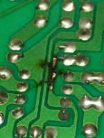
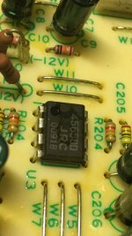
Please need some help and advice...:blush:
I am trying to convert my cellar to a musicroom. Most for stereo and sometimes movies or with a cold one watching Lfc play football. Concret walls and celings/ floor. Low in height just 208 cm. Room is 580x364 so appr. 21 m2. Not the best start. A wall to wall thick carpet and a acoustic ceiling is planned. The good thing is that one wall is made of fibreboard and gypsum. And i have made place of some sort of a bass absorber. I have room for a 60x208 cm trap that is almost 45 cm deep in each corner. My first thought was a slat absorber but hard to come down to room modes frequencies. I love the look of a slat wall made of walnut or alike. My lowest axial mode is 29 Hz according to Amroc calc. Next is 48 Hz at sidewalls. Then 59 and 88 Hz and so on. I plan to have speakers at the wall with basstrap playing at longer dimensions of the room. It seems to be easier to get down to lower modes with a wall with round holes instead of slats. Or is it best just to fill it up with absorbing material? Or will it be
a overdamped room? Is it possible to fix the modes from 30Hz to say around 240 Hz. It will be a large bookcase or something for storing at back wall behind listening position. First reflexes will be treated with a thick absorbent on sidewalls and ceiling. Back of room walls will be more diffuse/reflecting than absorbing I think. Any suggestions from you about my room and planning?
/YNWA

Side contact sockets that actually work?

Side contact sockets are clearly the work of the Devil - nobody else could have conceived of a more evil creation. They destroy tubes for a start, as you endeavour to get them in or out - look at how many have loose bases.

And then...... some of them just don't work, period. Can't get a tube in. Unfortunately I bought a batch of such sockets - shiny and probably Chinese with a small hole at the bottom. Complete rubbish.

I need some of these sockets, so can anybody point me to some that actually work reliably?

Attachments

  • Side Contact socket cheap.jpg
    Side Contact socket cheap.jpg
    710.3 KB · Views: 576

VFET amp Bourns trimmer exchange

I have started the small academic exercise to verify if the 25k Bourns trimmer is the root cause of a very small amount of on/off noise in R-channel. It is academic because it is only audible with ear very close to tweeter. But L-channel is almost 100% "dead" and could be nice to achieve this also for R-channel. While new 25k trimmers are on the way I did the removal of the old and also I measured a value for a R1 and R2 resistor if I should want to try this out and use fixed resistors insted.

The removal went very smooth. I used a smd hot air gun I got long time ago. A hobby version (Velleman brand). But it worked perfect. I adjusted the temperature to 390 C and set airflow to medium. After 10 sec. or so heat up I could pull out the trimmer.

I measured 3 resistor values (R1: 10k80, R2: 12k52 and R3: 23k30 (check value). I miss 20 ohm somewhere.....

I guess if I had a 12k5 and a 10k8 resistor I was good to go but I don't have these values. But it looks very close to some standard values.

I suspect the trimmer is the problem as it creates noise by just the slightest touch of the trimmer screw. But time will show......

23k3 is quite far away from 25k but within the 10% tolerance. So maybe you guys out there has a 23k in one channel and 27k in other channel? 🙂

Attachments

  • DSC_1668_00001.jpg
    DSC_1668_00001.jpg
    642.2 KB · Views: 616
  • DSC_1669_00001.jpg
    DSC_1669_00001.jpg
    717.9 KB · Views: 609

buzzy ground loopiness

Trying to finish up a rebuild project from years ago. It's a Rosenblit Grounded Grid preamp built on a turret board and installed in a Lite Audio enclosure with V-03 relay attenuator.

This was my stab at the grounding but it must not be correct.

attachment.php


It seems to be something with the V-03 board. I did try bypassing with an Alps RK27 and the buzzing went away.

A previous incarnation kept the signal grounds off the V-03 but the V-03 itself still had to be grounded to avoid a deafening hum.

Attachments

  • gg_grounding.png
    gg_grounding.png
    27.6 KB · Views: 217

Allen & Heath Xone 92 Pro DJ Mixer Value

Heard that these used xone 92 amps are highly wanted by DJ's. Expecially the older 2010 silver faced models. I saw a 2010 silver faced one in Silver Springs, MD for sale. Clean as a whistle, boxed, and with all the brackets and everything. What would be an asking price for these today? So far, I've seen the bidding go up to $1020.00. Id there anyone out there familiar with this UK model. Are these really going up in value? Your help would be very gratefu to me.

LM3886 Fault in Quad Vena II

Hi everyone. First post here, I've been lurking for a few days reading up on DIY Class AB designs as I'm part way through building a SC480 kit. Unfortunately that's not what triggered my first post. I just received a Quad Vena 2 from the UK (I'm in Australia). I'm aware that the only British part of the amp is the name, but it's still very nice and appears well build.

I had the amp running for ~30 minutes when it stopped... at the same time the oven timer went off. The brown smell was there but all the lights were on. The electronics tech in me couldn't resist taking off the cover for a look. No obvious destruction so I pulled out the multimeter. The pre amp and headphone amp still work, along with all the digital electronics. All the rail voltages are there. I checked the small signal input to the LM3886's and it's getting a signal. Absolutely zilch coming out of the chip though. I checked the mute pin and interestingly it sits at +4V relative to ground. The data sheet for the LM3886 shows a PN junction between the ground pin and the mute pin, so at minimum the mute pin should be -0.6V relative to ground. I know that the mute function needs -0.2mA to work, but I'm not willing to measure this just yet, for warranty reasons. I'd be interested to know what other's have on their mute pin; is it a negative voltage?

Here's the kicker, the amp came from the UK so it's set for 230V mains. There's a wire link that sets this, in my neck of the woods it should be in the position for 240V. That means the secondaries on the transformer will be too high. I think that the oven turning off and putting a jolt on my powerpoint may have been the straw that broke the camel's back. I've measured 75V across the input to the LM3886.

I'm reluctant to send the amp back to where I bought because of the shipping costs, and I haven't heard great things about Quad/IAG's customer service. If I can isolate the fault to the LM3886's then I'd consider swapping them out.

NAD 3020b

having a bit of trouble with this one.Im getting confused by the voltages im getting.Ive not tested all of it yet but i am working methodicaly backwards from the speaker terminals


it is simlar to the series 20, but there are differences.

heres what i have so far
all voltages are with the solder shorts in place


both channels are affected in the same way.


im getting high voltages from the speaker terminals, up to 6v so the centre is way out, and so is alot of the voltages elswhere


i have taken out and tested the main output transistors also Q609 and 610, these are all ok.


many thanks for any thoughts you may have.

Attachments

A question on the bar clamps force in building boxes

Hey guys ...

While building subwoofers it is understood to hold the wood pieces tightly together.

But what if we uses excessive force with clamps ??
The glue will come out, leaving only a thin film inside.
I am talking about a 90degree joint between any two box walls.

Is it not better to apply just enough and moderate force so that the two wood pieces come close without any gaps, and still decent amount of glue remains inside ??

ACA amp and speaker matching

I've built a couple of these ACA amps. But am having some trouble finding speakers they match well with. Thought a pair of Tyler Acoustics PD15s would be a good match since they are high sensitivity, but there must be an impedance issue in the bass or mid-bass region with these speakers because they distort easily in that range on bass heavy music.

What speakers have you successfully mated with an ACA amp?

Heathkit AA-151 troubles

I've recently recapped an aa-151 and replaced all resistors that were measuring out of tolerance. I've also replaced all the tubes. A little background of how this project all started though.

I inherited this amp and soon after noticed the el84's red plating. So a bit of googling educated me on what was happening. I wanted this amp up and running and also wanted to learn more about tube amps without having to take it to a repair shop so I took on the task of replacing the coupling caps myself. Soon after that I've since updated everything that needed replacing as mentioned above. The power caps were replaced with a 50/50 and a 30/30 JJ brand. All original caps (minus any ceramic) were replaced with CDE brand film, resistors are carbon film. The unit hums minimally and sounds good, however the main question i still need help with is the fact that I can't listen to it for more than 5 minutes without getting a headache/fatigue/sore ears. It's like there's some inaudible high frequencies being pushed but I cant say for sure as I don't have a scope or know what to look for. My ears are telling me something's wrong though. I've heard of maybe looking into 'bypassing the power caps' with smaller film ones but fail to understand what this would do to effect RF frequencies. Could it be any of the old ceramic caps in the tone section or any of the other carbon comp resistors that could be causing this?

any thoughts much appreciated....thanks!

Beer Budget Beam Steering

In pro audio, end fire arrays are a popular way to do beam steering.

Here's how they work:

4crI4XD.jpg

You take a couple of subs, and you place them in a line.
You pick a frequency where you want to control directivity.
You move one sub behind the other, at a distance equal to one quarter wavelength of that frequency.
And then you delay the first by a distance equal to that length.

A9WYBS9.png

CNW4mb1.png

So let's run a sim on this.

For my sim I am going to use a frequency of 200Hz.
It's true that this frequency is high, but I am using this frequency because of the limits of my simulation tool. But please note that all of this is geometric; the same things that happen at 200Hz will happen at 40Hz if you multiply all of the dimensions by five.

If we want to control directivity at 200Hz, then we'll want to space the front woofer apart from the rear woofer by 42.50cm. That's because 200Hz is 170cm long, and 42.5cm is one quarter of that.

In the sim, my woofers are 7" in diameter, and their enclosure is a cube that measures 8" x 8" x 8". (And, again, note that you'd get the same polar pattern at 40Hz with an enclosure that measures 40" x 40" x 40".)


CWNRb8m.png

Here's the wavefront shape of this array at 200Hz. We clearly see the 'heart shaped' cardioid pattern.

Jz8koty.png

If we go down one octave, to 100Hz, our array is a plain ol' monopole. This is one of the 'neat' things about end-fire arrays. When they lose their directivity control, they don't lose efficiency like a cardioid or a dipole. They just behave like a conventional box.

aUO7gub.png

At 400Hz, our array is a dipole. This is going to limit the bandwidth of our array, which is one of the reasons you only want to use end-fire arrays over a narrow bandwidth of 1-2 octaves. Obviously, this is no problem for subwoofers.

You may be curious why the end-fire array goes dipole. Here's why: We design it to work at one frequency, where the rear wave is 90 degrees out-of-phase. But that means that one octave ABOVE our target frequency, it's going to be 180 degrees out of phase. That's how it goes dipole.

Weird relay on a subwoofer plate amp, what does it do?

I've bought a subwoofer that works great sonically, but it has a relay which clicks from time to time and is driving me nuts. It seems most like some kind of auto-standby function: it clicks half a second after a moderately loud signal starts playing through the sub, and it clicks again some time after there's been nothing playing. But here are the weird things:

  1. It doesn't click as long as the input level is low enough (or, more likely, the output level of the amp). I mean, the sub is playing very well, it's doing its job, and as long as some threshold is not met, the relay does not click on.
  2. I can't hear any difference in the sound produced by the sub when it clicks on.
  3. But I can hear what seems to be 50 Hz hum coming out the subwoofer driver when the relay clicks on, and this hum ceases when it clicks back off.
  4. The time for it to disengage seems to vary, it's around a minute but it's not always the same. Maybe just an imperfection of an analogue timing circuit, temperature-related, perhaps? The amp does get warm the longer it runs - not super hot, but it warms up a fair bit.
  5. The power draw from the all with the relay off is 24-25 W, with the relay on it's +2.5 W - around 27.5 W.
Here are the pictures of the board and the relay (which seem to be pretty heavy duty): Imgur: The magic of the Internet


My questions are these: what do you think the relay is for? Can I just remove it from the circuit, or is it useful enough to keep (in which case I'll probably want to wrap in some sound and vibration dampening stuff so that it doesn't click as loudly)? Why does it make the speaker hum as it turns on?

EL84 push-pull without driver tube ?

I've been building a few EL84's projects lately and like this tube.

To my understanding, EL84's require only about 20Vp-p for full output.
I've got a Benchmark DAC3L, which can output +28.5dBu or 19Vrms or ~50Vp-p from its balanced XLR output with very low THD.

Could I use it to drive a quad of EL84's directly?
For P-I, perhaps an input transformer such as the Lundahl LL1690 or Sowter 3575

If this is feasible, I would appreciate assistance in designing such a circuit.

Toroidal transformers

Purchased a Antek AS 4218 transformer and see that it’s not round. The outer wrapping is not damaged but the donut, if you will, is clearly not round. I suspect this is not an issue but had to ask. The picture doesn’t really show it very well but I wonder if this is because of the rather large gauge secondary wires?
I haven’t used a toroidal before so this seems like a total rookie question

Attachments

  • 1CA0C40E-58D4-4B1A-95B2-98320A88B25D.jpeg
    1CA0C40E-58D4-4B1A-95B2-98320A88B25D.jpeg
    38.8 KB · Views: 232

Driver Stage Issue for SE Amp

Hello all,

I hope everyone is doing well during these times.
This is my first post and a call for help, so I appreciate everyone`s input and wisdom greatly.

I have built my first ever tube amp, a SE design from Popovich`s book on tube amps, and build a power supply for it from scratch. Now I wasn’t 100% sure of the power supply for this amp, but the idea was to supply all voltages from separate windings, with bridge rectifiers for each circuit, as they are cheap and available. Upon the turn on, to have only heaters and negative bias on, and then via separate switch B+.

I fed 2Vpp 500Hz sinewave signal from the signal generator to the amp, after the preamplifier stage it gets to 31Vpp, looking all good, after passing through one half of 5687 it is amplified to 50Vpp, but with the top of the sinewave well flattened.

While testing voltages without any tubes in the amp, the voltages vary quite a lot, but with all tubes in voltages drop closer to intended values +-10%.

And now the part that throws me off, is the driver and output stages. The driver tube`s grid has the correct negative voltage and seems to be all fine, but the cathode of the driver tube has reversed polarity, instead of negative as in the schematic I get the same voltage positive? Even it is connected to negative voltage?? which effectively makes output tube`s grid positive 😕 Why does this happen? I have a feeling that I must`ve got something fundamentally wrong here, but after the amount of time spent which is equal to wanting to smash this thing to pieces, I can't really find the answer :redhot:.
I tried to troubleshoot with the test lamp to see if there are any shorts, which there weren’t any. I double-checked all solder joints etc. and all seem sturdy, checked all the connections. I did try to change up a bias and driver`s power supply a little (version 2) where driver plate and negative bias were fed from the voltage doubler symmetrical circuit, to see if this makes any difference, but nothing. Did some other various changes to the power supply, but the result is the same,
I would really appreciate any help to get some output here.
Thanks,
Karolis
PHP:

Attachments

My thoughts. And nothing else.

I listen to this just now: ( from Original CD )
http://www.youtube.com/watch?v=V3JSDUOcG7M
CREAM: We're going wrong
(Jack Bruce)
Please open your eyes,
Try to realise.
I found out today we're going wrong,
We're going wrong.

Please open your mind,
See what you can find.
I found out today we're going wrong,
We're going wrong.

We're going wrong,
We're going wrong,
We're going wrong.

Gyuri.

PS.
I hope for it meanwhile, that possibly maybe not, after all.

EAR V20 Schematic wanted.

Looking at a EAR V20.

One channel has mains hum and crackling for about 2 mins from Switch on.
Only happens from 'cold'. If left over-night.
Once on and OK can be turned off and back on and will be OK. If left off for even an hour, will be OK.

All Valves (24x ECC83 + 2x ECC82) and Electrolytics replaced.
Still the fault remains.

Any thoughts appreciated.

P.

Any experience of ZVN3310 / ZVP3310?

I appreciate that these are not exactly new devices, but I needed some complementary MOSFETs that would work well at 24v Vds and 10 mA Id and I could not find many choices. The application being for a headphone amplifier based loosely on the Sony VFET front end in case you are interested.

First problem was finding any N/P matches. Based on a relatively small sample (3 lots of 10 each from different suppliers) I obtained a range of Vgs values for the above conditions:

• 1.928 to 2.205v for ZVN3310A
• 3.351 to 3.510v for ZVP3310A

Not even close! Are my samples unusual or are these devices poor complements?

Just as a check I measured Vgs threshold (for 1ma Id) and obtained:

• 1.35v for ZVN3310A
• 2.0v for ZVP3310A

Consistent with the above results but less than ideal.

It also looks like the transconductance of the P part is rather less than that of the N by comparing the additional Vgs above the threshold required to reach 10 mA Id. However, I did not verify this as I don’t currently have a suitable test rig. The manufacturers datasheet is also of little help at these low currents. Long shot I know - but has anyone with a curve tracer measured these parts?

Finally, my devices exhibit a significant amount of self-heating at the desired operating point despite this being approx. 240mW when the device is supposed to be good for 625mW at an ambient temperature of 25C (close to the temperature here today). I guess the e-line package is rather small… So far I have tried introducing 221R source resistors but these appear too small to prevent Id from creeping slowly upwards. I suppose I shall have to increase the value but I don’t wish to go too far due to the associated voltage drop and hence reduced swing from the front end of the amplifier. Any suggestions?

I would prefer to stay with MOSFETs rather than introduce BJTs hence also interested in suggestions for suitable alternatives, preferably ones that are actually obtainable!

Need help with a Behringer DCX2496!!!

Greetings!!!

So...two months ago I was writing a file to my unit and somehow the RS232 cord came unplugged!!

From that point on, the unit will not connect through the software. I can put the unit in boot mode but still nothing!!

I cannot write to it or read from it!!

I contacted behringer...they were zero help...told me to take it into a repair depot!! Well I'm an electronics guy as it is and the repair depot owner is a friend of mine!! He contacted Behringer and he had zero luck!!

With that, Behringer did provide me with a part number to order a new flash...so I did...$25.00!! And guess what?? The IC came blank!!! Nothing on it!!!

Like I said, I work in the business...I have an eprom burner at my disposal...and before you ask, yes, I put the original chip in but whats the point...its corrupted so the read from it is useless!!

I took the 1.6 bin from their site and wrote it to the blank...I thought what the hell but it still didn't make sense as the chip is a 4 meg and the bin file is only 500k!!

Seems that Behringer doesn't understand this concept as well...

So any ideas??

My unit was date stamped at 09/06...

Behringer did say that midiox may work in sending that 1.6 bin down to the corrupted chip but I have no way of working with a midi connection.

Can anyone help or suggest something??

Thanks!!

Advice for lundahll 1664 se amp

Hello to the community. The thing is- i have lundahll 1664 transformers se with 100 ma. I’m about to build se amp based on these transformers. They suit for both 2a3 and 300b. Currently i keep an eye on sun audio schematic as the standard one. Would anybody suggest better schematic for my needs? I’ve already simulated everything in orcad pspice and everything goes ok, ready to build pcbs. But.. maybe there is a more decent application? Your suggestions are highly appreciated.

AIYIMA Subwoofer Preamp Board.

I found this preamp board on Ali that has most of the features am looking for. Confused about a few things. The diagram is really low resolution.

1. Failing to see the subwoofer output, does it come out of the 5 pin connectors? If so will a 26AWG connector suffice?

2. Would like you use the same power supply for amp board. Its asking for this. " Power supply + v G -V is the power supply port, connect positive and negative dual power DC +/- 12v, or +/- 15V." Planning on getting a Mean Well LRS-350 9.7A.

a. Does Dual power mean something else beside + / - V and ground?
b. What is the best way to reduce the voltage from the powersupply?

(will this work): I was thinking about using a LM2596 DC-DC Adjustable Buck Converter 3.0-40V to 1.5-35V Power Supply Step Down Module. But It states "Keep it under 2.5 A and use the heat sink when working for long hours." Does this mean I have to reduce the AMPs before connecting it? There is no ground on this Converter, do I just use the ground from the power supply? Do I even need a ground?

Thanks

Attachments

  • PA5.jpg
    PA5.jpg
    41.4 KB · Views: 181
  • PA1.jpg
    PA1.jpg
    68.7 KB · Views: 186
  • PA2.jpg
    PA2.jpg
    64.7 KB · Views: 195
  • PA3.jpg
    PA3.jpg
    84.7 KB · Views: 170

Looking for TOSHIBA GT20D201 IGBTs

Hi guys,

In 2007 I bought a second-hand Sherwood TEMA A-1 and TEMA P-1 power and pre-amp combination together with an Advance MCD 203 CD-player and Paradigm speakers from Athens, Greece.
Up until this year I have been lucky enough to enjoy listening to the great sound of the TEMA amps.

Unfortunately a few months ago the TEMA A-1 stopped functioning. After a lot of work and effort I managed to figure out that there was a problem with the TOSHIBA IGBTs.
I searched in vain to find spares for these and was told that this kind of technology is now obsolete. The response to my queries from Toshiba Electronics Europe GmBH was that these are discontinued and are obsolete.
I've tried Sherwood US but they didn't seem to be able to help.
I've also tried contacting INKEL in S.Korea but they never responded.

Can anyone help me find a couple of TOSHIBA GT20D201 IGBTs?
I think that the Palmer LX 2000 PA Power Amp also had these iGBTs.

Any ideas/tips?

Many thanks

Tascam M-2516 mixer troubleshoot help?

I have this desk for recording with my Fostex E-16 reel-to-reel.

Some time ago I fried something in it by connecting a faulty active monitor into the right master XLR-output. There was an awful loud sound and I quickly turned everything off.

After turning the mixer on again, all that was heard is a steady clicking noise from all the master outputs, including the headphone.

Aux, talkback and groups work normally. My general suspicion is the faulty monitor gave mains back trough the main outs.

Taking it open I found this fried lead behind the op amp (see attachments mixer 1 and 2).

In the schematics, it's the lead right after U3's leg 6 (attachment monbusspcb).

Full schematics can be found here:

https://elektrotanya.com/tascam_m-25.../download.html

After making a jumper repairing it, sound started coming trough the input channels, albeit quiet and when taken to overdrive, the clicking returned but at least with some sound (see video).

Tascam M-2516 problem - YouTube

I proceeded to cannibalize two op amp chips from the talkback replacing U2 and U3 IC's as well as replacing caps C7, C8, C104, C106, C204 and C206 with no change in the problem.

Personally I've hit a bit of a brick wall on to where to look next so I was hoping someone could guide me to the direction maybe from the video sample and the description here.

Any help is much appreciated!

Thank you in advance,
-ekkhou

Attachments

  • mixer1.jpg
    mixer1.jpg
    90.4 KB · Views: 168
  • mixer2.jpg
    mixer2.jpg
    76.3 KB · Views: 169
  • monbusspcb.jpg
    monbusspcb.jpg
    135 KB · Views: 185

THAT1510 mic-preamp with digital control

First of all props to the basis of my design, beeing ThatMicPre!
Really nice circuit! :worship:
For my case however, I need digital control, but I also want to avoid small QFN parts...

So I started CADing a modified version. I added:
-Gain control using the DG412 switching IC (according to this paper)
-Digitally controlled phantom power
-Line in with combo jack

One downside is that the full 60dB gain can not be reached, because of the high on-resitance of the DG412...
How would you solve the task of digital control?


I would really appreciate any feedback on my edits.
Are there simpler solutions to this?
Any tips and tricks are very welcome!

Deluxe 4U faceplate option (8 M3 + 1 LED) - is this it?

Hi,

Can someone help confirm the $399 silver faceplate option is the right one to allow this mounting?

And can you confirm if the LED hole is not actually a full hole (as in, it does not penetrate the front of the faceplate but could be drilled out later?)

I just want to be 100% sure before ordering. Thanks!

Deluxe 4U Aluminum – diyAudio Store

20201122_155509.jpg
Projects by fanatics, for fanatics
Get answers and advice for everyone wanting to learn the art of audio.
Join the Community
507,774
Members
7,888,133
Messages

Filter

Forum Statistics

Threads
406,221
Messages
7,888,133
Members
507,774
Latest member
pete2000