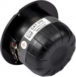
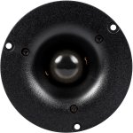
FS: 54 Fullrange Peerless TC9FD18-08 Line Array Project

Hello.
One of my friends wanted to build the Full Range TC9 Line Array project you can read here in DIYAUDIO forum:
https://www.diyaudio.com/forums/full-range/303417-range-tc9-line-array-cnc-cabinet.html

However, things has changed and he never started the project not will do.
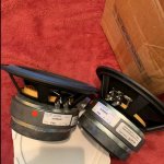
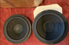
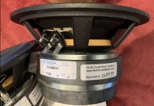
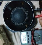
Drivers are in the box, new, never used.

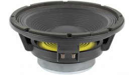
For sale: 54 Fullrange Peerless TC9FD18-08 for the Line Array Project
If there is someone interested, price would be 350€ for the whole lot of 54 drivers, much less than paid. Shipping costs and paypal feed to be added.


An externally hosted image should be here but it was not working when we last tested it.

An externally hosted image should be here but it was not working when we last tested it.
An externally hosted image should be here but it was not working when we last tested it.

An externally hosted image should be here but it was not working when we last tested it.

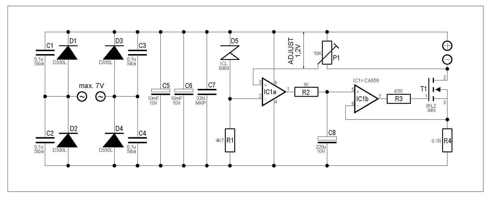
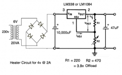
DC voltage regs for heater supply.

I'm not quite understanding the behaviour of the DC heater supply I just put together, and would welcome some explanation.

Circuit is a standard regulator one, from the usual data.

With a VS-KBPC602, Bridge Rectifier, 6A 200V I get:
Voltage into reg = 5.6v.
Voltage out of reg into 2x4V tubes @ 1850mA = 3.4v

With 4 Schottky diodes rated 5A, 40v I get:
Voltage into reg = 6v.
Voltage out of reg into 2x4V tubes @ 1850mA = 3.1v

Voltage offload from the LM1084 reg is 3.9v.

So why am I not getting 3.9v out? And why is the Schottky version only giving 3.1v out despite 6v in? The LM1084 is a LDO reg isn't it?

So to get 3.9v out do I just change the 470 ohm resistor until the voltage under load is correct?

The transformer is 6v, 20VA and doesn't seem to be getting hot, and nether is the reg hot.

Attachments

  • LM338 4v.png
    LM338 4v.png
    66.7 KB · Views: 385

Upgrading integrated amplifier tranformer

Hi All,


I have an integrated amplifier (fully recaped and few more tweekings), it's mains transformer is 200VA (2x28Vac) rated and I was wondering what will be the effect of replacing it's transformer for a higher VA rating and output voltage, let's say 300VA (or higher VA rating) 2x30v output ( can't find 28V output transformers, only 25V and 30V).

I attached the schematics of my amplifier's power supply section as a reference.


Thanks

Attachments

  • C2 power supply.jpg
    C2 power supply.jpg
    74.3 KB · Views: 271

Looking for advice on repairing an 845 amp

Hi. I’ve been asked to fix a Voxativ 845 amp. The 845 is driven by a 300B via an interstage transformer.

Around the 845 bias potentiometer there’s a blown 22uF/450V capacitor and a discoloured 5W resistor. In the first picture below, I’ve indicated the blown capacitor. The discoloured resistor is under the red wire below and to the right of the capacitor.

I removed the capacitor and resistor. The capacitor is showing a resistance > 20M. The resistor is open circuit.

A check of the other matching monoblock indicates that the blown resistor is 5.1K. Its matching resistor is not discoloured at all.

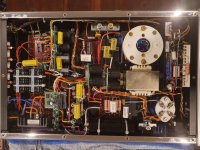
I’ve included a picture of the whole amp to give an idea of the complexity of it.

I don’t have the time or desire to try to reverse engineer a schematic for this amp and there’s no way the manufacturer is going to give me the schematic. Shipping it back to Germany from Australia for repair is not a great option.

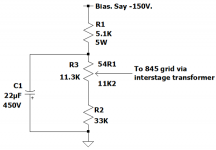
I’ve researched similar amps and my best guess at the circuit around the pot is shown in the 3rd image. The 5.1K resistor R1 is the badly discoloured and open circuit one. The 22uF capacitor, C1 is the one with the bulging top that's leaked everywhere.

Weird pot value but that’s what I measured. Current should be around 3mA which should be no bother for the 5W resistor. In fact, it makes me wonder why there’s a 5W resistor in there. The pot is tiny (10mm in diameter) so it doesn't have a high power rating.

I could just assume the capacitor went short circuit and replace the resistor and capacitor but I’d rather understand why the components failed in case there is some other problem.

Does the schematic look reasonable and are there any suggestions as to what might have caused the problem please?

Attachments

  • Dead cap.jpg
    Dead cap.jpg
    78.5 KB · Views: 285
  • full amp.jpg
    full amp.jpg
    991.9 KB · Views: 291
  • schematic.png
    schematic.png
    22.2 KB · Views: 297

Inset woofer

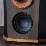
Looking at this build, what are the advantages and disadvantages of insetting the woofer behind a mitered baffle, versus a standard flush-mount on the baffle front?

These are the Fleetwood Sound DeVilles. I am not asking about how anyone thinks these sound, or even knows they sound, or how they feel about the design. I'm looking for some objective information about why this may or may not be a good speaker design idea.

I think the woofer used is a B&C 8NDL51 (I imagine they have it customized somehow for their use in this speaker, but I don't know for sure). Aesthetically, this design certainly works well, as this woofer has a large, octagonal spider which might look unbecoming on the DeVille's cabinet.

Other than that, I'm interested in some real-world information on this design choice.

Thanks,
Brad

Attachments

  • Inset_woofer.jpg
    Inset_woofer.jpg
    140.2 KB · Views: 216

FS: ATC mid & Scanspeak 18w

Have 1 piece of used ATC mid dome (not sure what model)- $300 USD
A pair of new creek audio enhance magnet ScanSpeak 18W/8545 - $400

Price include shipping and paypal fee to most common area. from S.E.Asia

Attachments

  • scanspeak 18w8545_1.JPG
    scanspeak 18w8545_1.JPG
    81.6 KB · Views: 368
  • scanspeak 18w8545_2.JPG
    scanspeak 18w8545_2.JPG
    143.6 KB · Views: 367
  • scanspeak 18w8545_3.JPG
    scanspeak 18w8545_3.JPG
    134.3 KB · Views: 372
  • 222.jpg
    222.jpg
    156.3 KB · Views: 369
  • 111.jpg
    111.jpg
    235 KB · Views: 377

Linn AV 5150 Repair Help

Hi guys,

I'm trying to repair a Linn AV 5150 subwoofer with hum. I acquired it from a gentleman here in Dallas. He tried to repair it unsuccessfully and was simply fed up with it so I picked it up trying to have some fun with it and maybe learn a little bit about electronics along the way.
When I inspected the board I saw a bad thermistor. (I was told that the board was sent to a repair shop where they replaced the capacitors and the board was tested OK). Any ways, I have the schematics for the power supply, the amp, the LED and the Fan controller. The schematic for the power supply shows a temperature sensor where the bad thermistor is. I have very limited education in electronics so I can't figure out the specs for the thermistor just by looking at the schematics. Can anyone here give me a pointer on how to take a guess at the specs of the thermistor?

BTW, Linn is no help. I sent them an email couple weeks ago... They haven't responded.

The attached PDF shows the temperature sensor on p. 3 where the thermistor is highlighted.

Any help is greatly appreciated. Thanks a bunch in advance.

This is crossed post in subwoofer and power supply forums.

Attachments

Volt VM752 vs VM753 mid dome difference

Can anyone tell me the difference between these two drivers?

Both are 75mm mid domes, but there appear to be subtle differences.

It appears the 752 has a larger diameter magnet than the 753, but the driver performancr specs are supposedly the same (for the 8 ohm versions). Not sure what the deal is here if there's only a physical difference and they compensated the magnet diameter with thickness.

They also list the VC assembly being different for both.

6S3P Tube for cathodyne application

The Russian 6S3P-EB tube seems to be a good candidate for Cathodyne PI. It has high gain and low plate operating voltage to allow direct connection. See charts attached.

However, I could not find any reference to this application. In fact, I can't find many applications for this tube on the Internet. Are there any reasons this tube is not popular for audio? Availability? Microphonic? Poor sounding?

Attachments

  • 6S3P1_page-0003.jpg
    6S3P1_page-0003.jpg
    248.2 KB · Views: 397

  • Locked
Should You Change Crossover Capacitors – The Great Debate

There are lots of posts here about perceived speaker performance improvement by replacing crossover capacitors with more expensive ones. Generally, I believe most of these so called improvements are nothing more than confirmation bias. But there is one possible scenario in which they are real.

If the crossover is initially equipped with electrolytic capacitors there is some chance that it is not operating as designed. Electrolytic capacitors are relatively inexpensive and have a very broad tolerance range. In some cases as much as +/- 20%. In that case the crossover would be significantly detuned and not operating at the point the designer intended. And that could degrade the sound.

Now if you replace that electrolytic with a different type of capacitor, say a film type for example, the tolerances are much tighter so you have moved the actual crossover point much close to the one intended by the designer. These tighter tolerance capacitors are more expensive than the electrolytics. Some reasonably priced types have tolerances of +/- 5%, but if you spend enough you can get some with a +/- 1% tolerance.

Changes from being 20% off to just 1%, or even 5%, could very likely be heard.

So some claims that replacing capacitors in a crossover improved the sound are probably real. But the reason given is somewhat misleading. It’s not simply because the replacement was more expensive, although that is true. The actual reason is that the new capacitor’s value was much closer to the designed value.

If you have electrolyics and a meter that can measure capacitance it would probably be a good idea to measure them first before spending a lot of money unnecessarily for more expensive replacements. Disconnect them from the crossover and measure the capacitance. If it is off by more than 5% from the nominal value it probably pays to replace it with something better. If not, you are probably wasting your money.

Experiencing a mysterious hum in a Parasound HCA-2200 II.

I have a hum that comes through the speakers. It doesn't change when I adjust the volume control, but it does get slightly louder as the amp warms up.

I read the manual and tried to bypass the ground with a cheater plug. No luck. So I took it to an authorized Parasound technician and he said he couldn't hear the issue. I figured it was the power at my house. Since then I have tried it at 4 different houses and the same thing happens everywhere.

I don't think the tech was lying. I honestly believe he couldn't hear it. It's pretty subtle. The tech says that he tested capacitors and everything was in spec.

Any ideas? Can someone help me out with a schematic? I'd like to be loaded with information for when I take it to a different tech.

BTW, this is my first post here. I am an active member at AudioKarma, but thought I'd branch out and try for help here. To say that I am a novice would be an understatement. I may not fully understand your advice, haha, but maybe I can take some of it to the tech.

Nick

How I calculate the surround stiffness and thickness

Hi there,

I have some questions about the surrrounds on a woofer. As stupid as that sounds, how do you know all the technical data? So how do you calculate how thick the surrounds have to be etc? If you want to have a resonance frequency of 22 Hz you have to calculate the mass and the surround stiffness. And for the surround stiffness I would need the thickness and the material. But how do you get such information?

Power JFETs in production

I'm pretty much a nube here, so I'm not exactly sure what makes for a good audio power JFET, but I got bored last night and found that Mouser is stocking and selling UnitedSiC power JFETs in TO-247 packages. They're making these things rated up to 85 amp and 650V. I'm too green to read the data sheet and really understand it, but I wanted to toss it out there for the crowd and see what I can learn.

SiC JFETs | United Silicon Carbide Inc.

Cyrus 2 Amplifier - 2SC1775A + 2SA872A Equivalent/Replacements?

Beginning work on a Cyrus 2 amplifier and Cyrus PSX power supply I recently acquired.

I have so far found that two of the power transistors on one channel are blown. They were 2x TIP3055. As far as I know these were NOT original parts and at some point must've been put in by someone... The original output transistors were marked in-house by Cyrus as PT77 (this is definitely not a standard transistor number and I must stress for anyone else reading this that the numbers on the bottom of these transistors are most definitely manufacturing date markings! Please stop wasting your time sticking '2SB', '2SA' and '2SC' in front of whatever numbers are on yours!) Through this forum I have found that TIP35C is a good replacement for them as is the MJE340/MJE350 for the driver stage transistors.

Without checking any further transistors or components yet I am also considering replacing the pre-driver transistors. These are proving tricky as they don't seem to exist anymore! They are 2SC1775A (NPN) and 2SA872A (PNP) and the datasheets are available here http://www.datasheetcatalog.org/datasheet/HitachiSemiconductor/mXuquxx.pdf and here http://www.datasheetcatalog.org/datasheet/HitachiSemiconductor/mXyzyuuu.pdf

If anyone can point me in the direction of a correctly specced replacement TO-92 packaged transistor I would be very very grateful! If it's available through Farnell I'll be even more happy (but don't let that last criteria stop you giving your input!)

Thanks 😉

Audio Note 300B Kit 1 - 0.015uF Capacitor pls help

I started the adventure to build myself the Audio One 300B Kit one, currently purchasing all the components.

There are 2 signal capacitors: 0.015 uF and 0.22 uF.
For 0.22 uF I found Miflex KPCU01 - Copper foil and polypropylene.
For 0.015 uF Miflex has only MKP02 which is a polypropylene capacitor not similar to the Cu / Al foil audio capacitors.

Searching for 3 days already everywhere and cannot find anything, not even on Ebay except some Russian capacitors.

Can you please help me?

I can find 0.022 but not sure if this higher capacity is ok to replace 0.015?

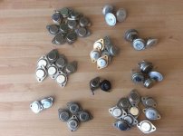
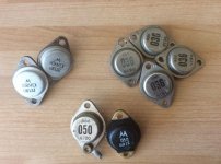
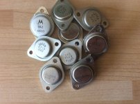
Help Identify These Transistors

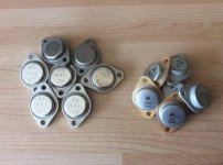
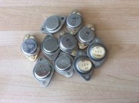
I recently acquired a ot of transistors mainly TO3 case but also some "flying saucer" ones.

They have strange numbers, probably house codes.

Can anyone shed some light on what they are?

Thanks.
Andy

Attachments

  • s-l1600.jpg
    s-l1600.jpg
    252.8 KB · Views: 296
  • s-l1600 (1).jpg
    s-l1600 (1).jpg
    254.8 KB · Views: 282
  • s-l1600 (2).jpg
    s-l1600 (2).jpg
    210.2 KB · Views: 280
  • s-l1600 (3).jpg
    s-l1600 (3).jpg
    250 KB · Views: 275
  • s-l1600 (4).jpg
    s-l1600 (4).jpg
    260.7 KB · Views: 504

Is it a broken compression driver?

So i bought two BNIB Faital HF204 in February and was only able to hook them up into my K402 horns. One of the speakers sounded normal, but the other one completely lacked high frequency extension. It was very obvious, but i ran a REW sweep and this is what i found:

attachment.php


I tried swapping amp channels and channels on the source, but it sounded the same.

How is it possible for a CD to be damaged like this? I always thought it either works or just doesn't. Maybe, it was damaged during transportation? Like fallen, shaken?

Attachments

  • HF204.jpg
    HF204.jpg
    172.9 KB · Views: 297

Behringer CX2310?

Is this good enough for my Altec 604-8H's? Decent price for them here in Canada. I know they're not the 2496's but I'm not sure I'm that sophisticated. 😉

Also if I am using RCA type equipment is it OK use over the counter adapter RCA to XLR adapter cables?

What are your thoughts/experiences?

Thanks for all input.

Behringer CX2310 Super-X Pro Crossover 2-Way/3-Way | Parts-Express.com

FS UK: Op Amps, Resistors, Caps etc

Clearing out all of my electronics as I'm clearly never going to get time to use them.

£60 worth of electronic components from mouser. Includes resistors, caps and opamps
This should include:
48 Kemet 0.033uF Caps, F461BB333F630A
4 Panasonic 63V 1000uF caps, EEU-FS1J102B
4 Vishay Rectifiers VS-E5TX3006-M3
16 NE5534AP Op Amps,
I'll throw in a +/0/- 12V linear psu (RRP £65+VAT) and anything else I find worth including.
£35 including shipping to UK only.

Is this glue or capacitor spill?

Hi mates,
Just purchased an old rotel RA-840BX4 which had a lot of dust and crap inside.
I've cleaned the pots and for a while I had sound from the two channels. After cleaning the board and components, one channel went silent and the preamp seems "funny".
One thing that's bugging me is to know if these caps are spilled or it's just some glue used in assembling. Can you please give a hand?


An externally hosted image should be here but it was not working when we last tested it.

An externally hosted image should be here but it was not working when we last tested it.
An externally hosted image should be here but it was not working when we last tested it.
An externally hosted image should be here but it was not working when we last tested it.
An externally hosted image should be here but it was not working when we last tested it.


Thanks!

Vented/sealed sub design

In reading on the net about Dunlavy Loudspeakers, I came across a post by someone who, if I recall correctly, worked for Dunlavy at one time.
The poster mentioned that Dunlavy woofer cabinets were ducted or vented enclosures that were inside of larger sealed cabinets.

Does anyone here have an opinion as to if this is even possible?
I'm getting ready to design a large enclosure that will house a smaller vented enclosure. Using either a 12" or 15" driver.

Opinions appreciated.

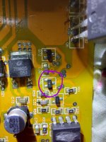
TDA8954 Oscillation Issues

Hi guys,

I'm having an issue with a commercial guitar amp that uses the TDA 8954 Class D power amp chip.

Came in with a note stating "Do not turn on. Output Caps need attention".

Hmm.. So I took it apart and found that the output chokes had become desoldered due to excessive heat. I cleaned everything up and resoldered them back. Turned on and the amp works just fine - for about 5 minutes... Then it shuts down. Inspection reveals that the output chokes are getting VERY hot indeed, (even without input signal) so is the surrounding area on the PCB. Turn OFF and then wait a couple of minutes and the amp fires up ok but then shuts down after a minute or two.

Normal operation for an overheat condition I'm sure. The amp chip runs in bridge mode with the output connected to a single large speaker.

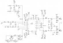
With no input connected to the amp there is a healthy sine wave on the output which is the same size both before and after the output filter. I'm assuming that the filter is not working (how much of the clock should I actually see at this point?).

Whilst I can see that this wave directly on the output audio is a bad idea from a speaker point of view I'm wondering why the amp shuts down and gets really hot. It's an 8ohm load but I would think that even with a bad filter, it should be able to cope with this. I've read some posts here about a 20uH filter not being large enough for an 8 Ohm load but I'm not sure if this is just someone's point of view or whether it's correct... ?? Supplies are + / - 40V so pretty standard for this design.

Since the amp works ok but "just" overheats I'm again assuming that the chip itself is ok so do you guys think that the only issue is the output filter itself? If so, I'll go ahead and replace all the filter components and see where we go - or do you think the overheating issue cause may be elsewhere?

I haven't done it already because the amp components are on both sides of the board, it's a real pain to take out (about 25 bolts and nuts to remove) and I can't operate it with the board out of its housing.

I'm unfamiliar with this particular chip so if anyone has worked with it could shed some light on the subject I'd be grateful.

Pic included of the actual circuit I'm looking at.

Many thanks.

Attachments

  • TDA8954 Amp Cct.JPG
    TDA8954 Amp Cct.JPG
    110.7 KB · Views: 350

Beyma SM110/n for 2 way low power speakers.

Hi
I have a pair of Beyma SM110/n.

Are 8ohms 96dB.

Somebody know if is a good option for do a two way speakers with 1800hz crossover aprox.

I know would be better 6 or 7 or 8 inch driver for the dispersion, but the Beyma is enough efficient.

I have a 300B amp.

Attachments

  • 1902221719111158_01_medium.jpg
    1902221719111158_01_medium.jpg
    16.2 KB · Views: 468
  • 81Q+CMarvUL._AC_SL1500_.jpg
    81Q+CMarvUL._AC_SL1500_.jpg
    167.9 KB · Views: 464
  • 91bVrAHNOGL._AC_SL1500_.jpg
    91bVrAHNOGL._AC_SL1500_.jpg
    328.9 KB · Views: 468

MTW driver placement + surface-mounted mid

Hi, I notice in Troels' Faital 3WCs + Spendor's Classic 3 ways, an MTW arrangement is used, with the midrange driver surface mounted in the former.

time-alignment-1200.jpg


spendor.jpg


Is the MTW arrangement used primarily for improving time-alignment? Does it cause other problems? And does surface mounting a midrange negatively affect diffraction from the mid and/or tweeter?

I'm gathering ideas for a simple 3-way, and surface mounting would seem to make the woodworking easier.

help just help, newbie to DSP/Sigmastudio

Hi All, and to ANYONE who can help/direct me to where I may find help!.
I have a wondom/Sure Electronics JAB3 amp board ans ICP3 DSP programmer, same as dayton except rebadged I think. I am following all instructions I can find on the net about a good starting point but keep finding this error. I have tried on main PC and my laptop with the same errors.
An externally hosted image should be here but it was not working when we last tested it.

I am designing and making modern music playersd and would like to be able to tune the sound before putting on sale and I just dont know where to look for help!
Thankyou in advance for ANY help/advice you can give 🙂

VT25/10Y filament help

Hi.
In my VT25 I'm using these filament supply.

FilamentSupply1.jpg.f68ed173ffb1810e78310ddfcd26bea5.jpg


Problem is when I turn on preamp for 1 second I have big glow from valves.
I tried to measure output voltage from filament regulators and it is around 10V for couple of second and then goes to 7.5V.

I'm suspecting problem is low resistance of filament when they are cold.

I never had that problem with these regulators when I used 300B tubes, only with VT25.

I'm just afraid that these tubes filaments will break eventually because of that.

Is there any way to edit this schematics to have slow start?

Sounddstream 1200.1 blown output

Hey guys. So got this amp in with blown outputs.(640Ns)
Before I just threw new ones in I scoped the pads. On one side of the amp the wave was perfect square wave. The other side was like a sine wave.

So I did a few more checks and noticed 1 of the buffer chips had died (2T)
Replaced that. As well as checked components on the driver board which all apprear to be ok. As I've come to notice amps that run buffer chips usually they let go and the driver board survives. ?

Anyway. I fitted up all brand new fets all 8. (4 each side)
I was putting the (sine wave) down to there is a high and a low side and I think I remember one of them U can never get a proper reading from. So made sence that I was only getting a square wave on one side..

Anyway fitted new fets. Have audio but very weak and sounds not very good. Also the louder U go the fets on both sides (more so the side with the sine wave) gets very hot. So I shut it down for further probing. And I can see the 2X buffer that has the usual hole in the top that U come to find when they have taken a hit. (But reads ok?) So about to swap that out but just looking for suggestions. I do not have any scope photos but can get them if requested.

All 10ohm gate resistors have been replaced. I'm having trouble uploading photos so I'll try again soon

Edit. Have checked all the new mosfets on a transistor tester and the 'VT' are the same or within 0.1v of each other

Attachments

  • 20210919_113916.jpg
    20210919_113916.jpg
    555 KB · Views: 87

The Best Active Crossover - Here!

There have been many threads on active x-overs. I wonder how many of those who have suggested one type of crossover or the other have critically listened to the suggested crossovers versus others. Not to undermine anybody's credibility but a genuine doubt arises when subtractive crossovers are preferred to simpler forms like 2nd order LR.

I have listened to many types of crossovers and orders and have found that each of them are certainly not short of faults. In my opinion the 4th order subtractive crossovers which use All Pass delay networks for linear phase at the output, are the worst sonically. The cut-off profile is nevertheless good and oscilloscope shots leave very little to be desired; however, sonically they cause a blur in the midrange and the transient response plus definition in the bass region is very poor. I think that this is due to higher group delay. The ones that use Low Pass Filters as the active elements before subtraction are the worst offenders.

There are those that use cascaded 1st order High Pass Networks to obtain a 4th order x-over, but the bass suffers quite a bit in these types.

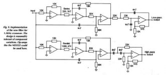
Sometime ago Electronics World published an article entitled "Precise Active X-over". I have referred to this in past threads. I am posting the schematic as an attachment. In my opinion, this is one of the best crossovers sonically. I have configured the orginal two way into three way by duplicating the two way network at the output of the High/Low output. I preferred to tap off the Low output to the Amp, but pass the High output through another two way network to obtain Mid and High outputs. This has been critically tested in domestic environments with highly satisfactory results. The real test for all of the networks mentioned above have been in Professional Audio outdoor work, where 18" drivers are used in Horn-loaded Bass Bins, 12"/10" drivers in Mid Horns and Horn Tweeters are used. The blur in the mids or the slight lack of transients in the bass is all too evident then.

One could improve on the active elements used in the crossover. The schematic shows the NE5532s. I have tested various op-amps including OPA2604s. Each do have a sonic signature. My idea is to try out discrete op-amps, as illustrated in the Passlabs site and use higher operational voltage to avoid a bottleneck after the preamp. The use of low impedance buffers at each of the outputs of the crossover would be a very good idea. Alternative arrangements could be FETs used as followers or the BJT buffers as used by LC Audio.

Perhaps, the one exception to these comments could be the PassLabs Active Crossover which I have not yet auditioned.

This active cross-over is highly recommended for the critical audiophile, especially with refinements to the active elements. The values shown have a nominal crossover frequency of 1500Hz. You can change the frequency by changing the value of all the capacitors leaving resistor values constant.

Attachments

  • precise x-over1.jpg
    precise x-over1.jpg
    17.1 KB · Views: 9,551

Wire (insulation) for refurbing PT output wires?

I have an Eico HF87 I am refurbing into an HF89. The bias voltage wires are to short as they were clipped off for use in the HF87 which uses cathode bias. and the HV leads are just shot, can't pull insulation off without breaking the wire itself. So I've exposed the works and need to replace the leads.


The info in the Eico manual regarding transformer temperature states: transformers operate under 195'F with a safety margin to 221'F


That's pushing it for margin of safety with the 105'C wire I have.


I'll have to order something. Not sure what I should get. Any recommendations?


Thanks!

From SW to AKABAK with mesh-files

Hello guys,


For a project I want to use Akabak software. The idea is to simulate acosutic wave scattered cones of differents shapes. Shapes of the cone are simple (straight, log, circular, etc ...).

I'm used with Solidwork, this is why i'm using it for CAD. But I can't succed to import those simple geometries is Akabak through mesh-files ...

Does someone tell me what to do for that? Ofc if you're using another CAD software, I can adapt myself since I just want to draw very simple shapes.


Thanks, Elliot


Ps: how do I solve a topic? ty

Regrets

A post to talk about those "hindsight is 20/20" things in life.

I choose to miss the Pat Metheney show he did 10 days ago here in Olympia. 15 minutes from home; that's not happening again any time soon - or perhaps even in this lifetime.

Enclosed venue and I just chickened out due to stupid covid. Vax status required - probably would have been OK. Probably. I heard about it well in advance, but didnt give it much thought, just "nope".

Listening to an interview with him this morning on San Diego Jazz 88.3. They have a shell where he'll be performing outdoors...

ADCOM GFA-555 Amplifier Upgrade

Our audio shop has closed due to retirement and I would like to share our mod for the ADCOM GFA-555 power amplifier. I hope that this will help some of you who would like a little better sound quality but the mod will improve clarity first and foremost.

Attachments

Vifa D76MX/ SS D7608 3" mid dome in PE waveguide

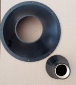
Working on a project with the Vifa D75MX-41-08 / Scanspeak D7608-9200 dome midrange that I want to couple with a modified PE 8" waveguide. I don't have the part number to the WG, but it was the only 8" threaded guide PE recently sold, so that should narrow it down.

I managed to remove the throat portion with a router bit chucked in a small drill press, which worked very well. It took some patience and care not to be overly aggressive with the feed rate since the plastic wants to melt and bunch up. I'm very pleased with the results.

The opening I made is just large enough for the dome without the surround.

Now to the tricky part - building (or 3d printing) an adapter to bolt onto the dome flange. I dont want to permanently attach the WG to the mid flange so that I can still change things as I go.

The magic question is, would it be better to shade/cover the surround and only allow enough gap for dome excursion and surround movement - OR - enlarge the WG throat to fully expose the surround? My gut says shade it and allow just enough gap for dome excursion. If so, I was going to accommodate the surround profile in the adapter flange.

Obviously it would be smart to perform measurements, but I figured I'd ask here first since there are quite a few dome tweeter / WG experts on here that have done their homework on this. Please share your thoughts on how I should proceed.

Attachments

  • 20210914_123933.jpg
    20210914_123933.jpg
    704.8 KB · Views: 499
  • 20210914_123905.jpg
    20210914_123905.jpg
    360.2 KB · Views: 481

Help with calc. for 10" woofer for TL sub?woofer?

I have 20 year old transmission line speakers that need new woofers. The OEM woofers and are no longer made and I don't have the specs on them. I never thought they were the best thou. Unfortunately I am inept at the formulas and programs to simulate a TL speaker. I am therefore humbly asking for help. I can provide fairly accurate info on the cabinet. It's a "classic" folded design with the woofer at one end of the line.

Volume about 2.9 cubic feet
Line length about 7.2 feet lightly stuff for the first 6 feet. A Stereophile review of the speaker (Innersound Eros) said the tuning of the line was about 30Hz.
The line is tapered from about 135 square inches at driver. At about 6.5 inches down the line it is 81 square inches then at the the terminus it is 36 square inches.
It will crossover at 48dB/octave at 170Hz
I am using biamped external crossovers and Dirac room correction.
I don't listen at high SPL but in my room Dirac boosts at about 50Hz by about 9dB.
If someone could just use the software to guide me on what specs simulate best.
Here are some woofers that seemed possible to me in case someone has specific recommendation but mostly I just need some direction on what specs I should aim for.
Seas Prestige CA26RFX (H1305)
Seas Prestige L26RFX/P (H1209)
Scanspeak Discovery 26W/4534G
KEF B139 SP1044
Thanks,
Doug

How is d3 dominanc avoided in some PP designs?

Hi,

I've been trying to study a number of power amp designs lately. I'm attracted by SE designs mainly because of the THD profile where d2 dominates d3. But then, there are the obvious drawbacks. Now, there are some PP designs out there that feature a THD profile where this is not the case. (For example the PP1-C, PP2-C)
What is being done differently in those design? Is it just the absence of NFB?
I mustsay that I am not completly clear on why, in general, PP tends to exhibit this particular profile. Again NFB is probably a contributor but what are the other factors at play?

Cheers,
Lars

Lowering a crossover point in an active sub

Hey guys! New to the forum, and new to audio-mods.
I've built guitar pedals and basic cabinets in the past, so I have soldering skills, and some basic DIY knowledge, but I'm a novice in the field.

I recently bought a Gemini 300 portable array, and the thing is surprisingly nice!
But it comes with the flaw of a 200hz crossover point for its subwoofer, making things a tad muddy.

I want to mod the built-in crossover to drop that frequency down to 120hz.
Downside is, I'm not sure how to go about it, as I lack the mathematic knowledge and experience on the subject.

Any suggestions?

Influence of port volume?

I can't find information on this anywhere. Does port volume effect its efficiency?

e.g. A cabinet contains a 50mm round port 100mm in length representing a tuning frequency of 50hz. Port volume = 196.25cm3.


To maintain the same tuning frequency using a 100mm round port I'd need to increase the port length to 600mm. Port volume = 4710cm3. The second resonator has almost 25 times the volume of the first. Does this make it more efficient in the way larger drivers are more efficient than small drivers. Or does just enable the vent to handle greater SPLs, or both?

I have another bizarre question with regard to port material. Our first experience of a Helmholtz resonator is when we blow across the top of a glass bottle . . . try it with a plastic one - it doesn't work so well.

Make up your mind - is it a Quad 405 or what?

It may be just my sometimes weird sense of humour:


But have look at this: HiFi MJ15024 Digital Power Amplifier Assembled Board Stereo Audio Amp Module 894177238379 | eBay


So this is a "HiFi MJ15024 Digital Power Amplifier Assembled Board Stereo Audio Amp Module"


OK, but what does the text on the boards "QUAD 405" then mean?
The number of transistors, the use of a LM301 and the polarity of all power transistors matches a QUAD 405 - but where did the Digital Power then come from?


BTW: I stumbled on this while examining another link from diyaudio.


Cheers,
Martin

DIY heatsink

It's been a while, but I'm back.

Here's a little thing I thought I would share. It's actually going to be used on a chineseium Douk 2.1channel amp with 4 LM 3886 chips, but what I'm sharing is an inexpensive way to make what I think will be a decent heat sink.

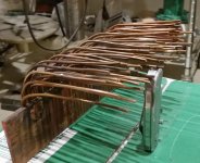
Copper is one of the best conductors of heat out there, and it's easy to work and join with solder. I had a chunk of 1/8" x 2" bar and 400MCM cable, and thought what a unusual but possibly quite effective material for a heat sink.

So, going from memory, it's about 9" long chunk of bar with (you count them) a bunch of pieces of 10ga solid copper wire about 6" long. They're all lined up, then soldered to the bar. I used plumbing flux and nolead solder and a map gas torch, but you could use a large wattage iron. I fluxed and clamped all of the wires with a bar of aluminum so it wouldn't stick, then heated and soldered. After it cooled, I sand washed, then sand blasted and coated with a thin coat of aerosol poly. Last, I drilled and tapped holes for mounting.

I'll let you know how it works...

Attachments

  • Douk HS1.jpg
    Douk HS1.jpg
    198 KB · Views: 1,564
  • Douk HS2.jpg
    Douk HS2.jpg
    266.9 KB · Views: 1,342

Another version of the Doug Self Preamp

Start 2 years ago after i bought, finish and test the Carl_Huff kit.
New design and new layout with the option to try different potentiometers and input caps.

The PSU is in the same PCB with LM317 & LM337. Adjunction also of a Phono Preamp.


Thank you to Gianluca from Modushop for the front and rear panel, was not easy to center the printing with the holes,
they use 2 different machines and between tolerances and everything they could be slightly off center, but they are prefect.
And of course thank you to Doug Self for this wonderful Preamp.

Attachments

  • IMG_3335.jpg
    IMG_3335.jpg
    700.5 KB · Views: 578
  • IMG_3337.jpg
    IMG_3337.jpg
    672.6 KB · Views: 543
  • IMG_3339.jpg
    IMG_3339.jpg
    574.8 KB · Views: 519
  • IMG_3340.jpg
    IMG_3340.jpg
    666.7 KB · Views: 496
  • IMG_3345.jpg
    IMG_3345.jpg
    715.6 KB · Views: 501
  • IMG_3347.jpg
    IMG_3347.jpg
    525.5 KB · Views: 323
  • IMG_3349.jpg
    IMG_3349.jpg
    526.3 KB · Views: 326
  • IMG_3351.jpg
    IMG_3351.jpg
    894.8 KB · Views: 379
  • IMG_3352.jpg
    IMG_3352.jpg
    821.4 KB · Views: 355
  • IMG_3355.jpg
    IMG_3355.jpg
    919.3 KB · Views: 335
  • Like
Reactions: asuslover

moving coil loading

ok, moving coil cartridges are said to be less susceptible to capacitive loading than mm's.

But the coil inductance will still resonate with the lead and input cap., which the loading resistor damps.

so we should vary the load resistor to get a flat response.

Not much is said about the lead or input cap tho', surely to get the correct value resistor, we need the correct value cap. as well, so how do we work this out. We should know our cartridge inductance, so we can calculate damping resistor by square root of (L divided by C)

And why do mc stages still have input caps, surely they could just use lead capacitance?

And what's all this about using resistors to do mechanical damping, too? bit confused....

Military HV Hi Current Heavy Duty Connectors FS.

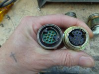
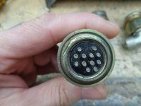
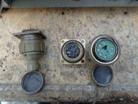
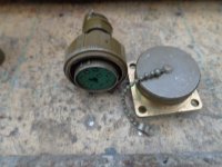
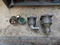
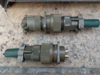
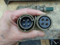
Bought these a while ago, will never use the all. Plessey Mk4 & MK7 as well as Cannon Multi Way connectors, most NOS, some used. Some are complete with all washers etc, some not, but all are useable. Ideal for connecting valve/tube amps and power supply's. Each has a chassis mounting socket and accompanying plug. see pics.

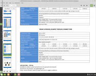
Specs are 250v to 2.5kv, see datasheet attached. Not 100% sure of the 2.5KV rating, but they should be ok for a good 500v.


First up 6 12 way, looking at datasheet good for 5A. Two complete with caps - £7 each. Three used - £5 each. One missing a cable strain relief. - £4.


Two big 9 way (19A) with caps, one with cable grip £7,one without £5. One big 6 way complete - £7


Two 3 way (19A) with 90 deg "elbows" - £4.50 each.


Lastly two big 4 way (60A) with caps complete, one with plug - £7, one with covered chassis socket & strain relief - £8


For postage drop us a PM, Andy.

Attachments

  • DSC00052.JPG
    DSC00052.JPG
    162.4 KB · Views: 180
  • DSC00053.JPG
    DSC00053.JPG
    162.7 KB · Views: 184
  • DSC00054.JPG
    DSC00054.JPG
    161.2 KB · Views: 176
  • DSC00055.JPG
    DSC00055.JPG
    161.4 KB · Views: 177
  • DSC00056.JPG
    DSC00056.JPG
    159.5 KB · Views: 169
  • DSC00057.JPG
    DSC00057.JPG
    161.6 KB · Views: 80
  • DSC00058.JPG
    DSC00058.JPG
    160.8 KB · Views: 83
  • DSC00059.JPG
    DSC00059.JPG
    162.1 KB · Views: 87
  • MK4  7 connectors.png
    MK4 7 connectors.png
    212.5 KB · Views: 92

Qcc3008 or csr8675 mono programming

Hi guys, i’m trying to get a mixdown mono output fron either the qcc3008 and the csr8675. But the only thing i get is a left channel only audio. I cannot figure out any way to get a mono output from that two boards. I tried Adk Config tool but i cannot find a way to go. Does anyone figure out how to do that? I get pretty easy result with csr86xx series config tool on older models of boards but these two are very hard to program in mono. Any idea? 🙏✨🤍

please help me I want to repair SAE PXM10x but no circuit.

please help me I want to repair SAE PXM10x but no circuit.😕

Please help me if you have a circuit of it.

An externally hosted image should be here but it was not working when we last tested it.

An externally hosted image should be here but it was not working when we last tested it.


An externally hosted image should be here but it was not working when we last tested it.
best 18” drivers that can go flat 20Hz

Hi Guys, I intend to build 4 way active horn speaker ,hopefully if possible something similar to OMA top of the line if I could get hold of plans for the conical horns. Otherwise I'd build 4 way Horn speaker on close enclosure with some matching wooden horns. I'd appreciate your advice concerning the bass which I'd like it to go down as possible to 20Hz.The options are AEspeakers TD-18H,BMS 18S430V2, ,Ciare 18SW,Beyma 18PWB1000FE,JBL 2245H,Mccauley 6174 ,however the cheapest driver is $400 and goes up to $800 per unit .On the other hand I saw a driver from Dayton Audio PA460 out ofwhich it's FR:26Hz-2kHz,97.8db,Fs-28.3Hz which merely cost $180 per pair ! Could someone let me know if the above Dayton is so inferior to the others or would I get 99% similar quality tight base without distortion ? I'd appreciate any solid recommendation even completely different ,since I haven't had the chance to hear any of the above drivers,hence am clueless which one will give me the best results !

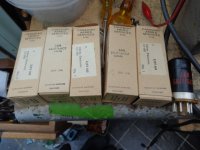
Five NOS JAN 6AJ7/6AC7 Cheap.

Five NOS 6AJ7/6AC7's for £4. These are JAN Canadian Armed Forces. I have about 6 lots.These are pentodes but check out the triode curves, see attached, not bad,pretty linear.


Postage to EU £6 approx, USA about £9, UK £3.20.


PM me for details re postage to your specific location. Andy.

Attachments

  • DSC00051.JPG
    DSC00051.JPG
    162.2 KB · Views: 73
  • 6AC7 triode.JPG
    6AC7 triode.JPG
    162.5 KB · Views: 82

CV2799 valves & NOS B7A bases.

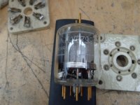
For sale four NOS CV2799/QQV03-20A valves - £7.50 each. These have been tested for emission and test within spec. Not in original boxes but in original packing

Six ceramic military WERC B7A valve bases - £7 each.
See pics.


Can post to USA & EU but you may need to pay customs fee's your end. Postage to the EU is approximately £14.10 tracked/confirmed or £10.20 economy, no tracking 3-4 days. USA is about £22 tracked and confirmed or £9.50 economy, no tracking, customs fee's may apply. Postage to UK mainland is £3.20. Sorry, can't lie on customs firms.


Drop us a PM if interested,might knock a few bob off if you want all the bases or all the valves if you ask nice. Andy.

Attachments

  • DSC00024.JPG
    DSC00024.JPG
    158.2 KB · Views: 89
  • DSC00025.JPG
    DSC00025.JPG
    162.6 KB · Views: 92
  • DSC00023.JPG
    DSC00023.JPG
    160.5 KB · Views: 93
  • DSC00021.JPG
    DSC00021.JPG
    161.9 KB · Views: 86

Arcam Delta 290 Integrated - Please have a look.

Hi All,

I have moved this plea for info from Everythin Else to this more appropriate area.

Just a few days ago I was wanting to listen to some music and got a bit if a shock!! I am using a 290 Integrated as a pre with a couple of 290P(power amps) in bridged mono. When I turned up the volume in the integrated to the normal 9 o'clock position, the amp relays kept on cutting out (LED to orange and no audio output) and resetting themselves. The right-hand monoblock was also resetting itself in a similar manner. When I switched from direct mode on the pre to indirect (i.e tone controls and balance now active), the amps would reset. If I moved the volume, the amps would reset. Funnily enough, I had output when I was runnng the pre in mono.
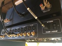
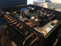
Having had a dustly input selector causing previous problems that I cured with switch cleaner, I took the amp to my bench and had a look at the insides. I was expecting to find evidence of a blown component (scorch marks etc) or two, but, except for a lot of dust that I cleaned up, everythin looked fine. I used the switch cleaner and reassembled.

When I powered up the system, the symptoms were still the same, but I noticed that the volume on the pre had to be turned way up to hear any output at all on the left channel, the right was dead and any switching made the relays click out.

Before I send the amp back to ARCAM for repair, has anyone got any clues as to what may have happened here? My thoughts are that perhaps an IC had partially failed (on the right side circuit) and then fully blown (because the gain is so tiny now that I suspect it is purely the line level of the CDP output and the 290 integrated has become a passive preamp!!!!

Any thoughts would be very gratfully received.

Cheers

Jon:cannotbe:
Projects by fanatics, for fanatics
Get answers and advice for everyone wanting to learn the art of audio.
Join the Community
507,913
Members
7,893,461
Messages

Filter

Forum Statistics

Threads
406,477
Messages
7,893,461
Members
507,913
Latest member
rajkps4