High output voltage from power supply - Hafler DH-220

I recently fixed up a Hafler DH-220 which had a dead channel. Before I began I noticed the voltage across the +voltage fuse for one channel was 65v and the other was 85v. After the repair, and upgrading the capacitors to 22,000uF 80vdc, I'm seeing 84v on both channels. Is this something I should be concerned about? It runs fine, bias and offset calibrate fine. Just confused at the voltage I'm seeing.

Dual mono vs single PS?

Logic dictates that a dual mono build (or mono blocks) will offer improved performance / sound quality vs a traditional stereo amp sharing one PS. Has anyone any experience of actually comparing the same amp but built with these different configurations? I’m curious, all aspects being equal (eg total VA rating of the transformer(s)), how much difference does it make in practice?

Upgrading 2.1 ebay system. Help

Greetings!

First a bit of background. I'm 22 and my family owns a small vineyard where I can throw parties and hang out with my friends.

We listen to everything there from rock/metal to rap and techno depending on the squad's preferences that is there hanging out.

Currently I have a 2.1 50W amplifier board from ebay there powering my dads old Magnat speakers and a Subwoofer from sony's home theatre.

It's ok the way it sounds for the aplication but when you want to turn it up all the way it starts cutting out (probably the power supply's fault) and the sound quality isn't greatest and it lacks volume.

Would an old 90's stereo amplifier like Sony F319R
(Sony TA-F319R Integrated Stereo Amplifier Manual | HiFi Engine) or something similar that goes for around 50USD used locally make sense to buy? I was thinking of buying a separate amplifier board just for the bass and running either a y splitter or powering it trough a low pass crossover/filter from the B side speaker out.
Or would again an all in one 2.1 board from ebay make more sense?

So I would like to upgrade the existing setup but I'm not totally sure witch route to take. My budget is around 75USD and I wouldn't like to go much more.

Every suggestion is welcome and feel free to ask questions.

Thanks, Sven.

Tannoy st100 crossover

Hi all I have been listening to my brother tannoy super tweeters. And I am very impressed with the overall sound quality. Does anyone have a schematic diagram. As I have brought all the value caps and board to possibly create my own super tweeters. If anyone can help me out with the images to see what goes here and there. These are the photos I have from my brothers super tweeters. As you can see the red line indicates where things are going but sadly there are a few where I can’t make heads or tails over. Any help would be really appreciate. Many thanks

Attachments

  • 090835D3-0721-4BCD-B330-5E6FD9E069CD.jpeg
    090835D3-0721-4BCD-B330-5E6FD9E069CD.jpeg
    206.4 KB · Views: 208
  • F56D3916-4785-47FE-AB5E-407C7AC76876.jpeg
    F56D3916-4785-47FE-AB5E-407C7AC76876.jpeg
    214.3 KB · Views: 203
  • 6D044793-6812-4856-9C2B-4B1D9F4EB1BD.jpeg
    6D044793-6812-4856-9C2B-4B1D9F4EB1BD.jpeg
    169 KB · Views: 185
  • 629D1714-73BD-4A8A-AE80-0D98888E36AC.jpeg
    629D1714-73BD-4A8A-AE80-0D98888E36AC.jpeg
    156.1 KB · Views: 180
  • 7A308AAC-73D4-4092-8318-218E8C325EAF.jpeg
    7A308AAC-73D4-4092-8318-218E8C325EAF.jpeg
    158.8 KB · Views: 160
  • 8448CEC7-D16B-455D-BDEF-7A764C77308B.jpeg
    8448CEC7-D16B-455D-BDEF-7A764C77308B.jpeg
    133.7 KB · Views: 133
  • 79248D50-8FFB-4B93-B539-8234EE7B396B.jpeg
    79248D50-8FFB-4B93-B539-8234EE7B396B.jpeg
    159.8 KB · Views: 112
  • 78F63BA4-6379-4686-9E49-44C8BD073EC6.jpeg
    78F63BA4-6379-4686-9E49-44C8BD073EC6.jpeg
    133.7 KB · Views: 119
  • 8B6DEC02-3F59-4FC9-B2A5-CCDE7188174F.jpeg
    8B6DEC02-3F59-4FC9-B2A5-CCDE7188174F.jpeg
    109.7 KB · Views: 118
  • A8BB73D2-1853-48BD-8F3D-57D33B306799.jpeg
    A8BB73D2-1853-48BD-8F3D-57D33B306799.jpeg
    133.7 KB · Views: 132

Bass driver for SET tube amp

I am designing a 3 way speaker for a friend who has a 6AS7 SET tube amp and need some advice on the woofer alignment and driver choice.

Woofer size will be 12". He does not play music loud. Efficiency is important but I'm also trying to get a decent extension in the bass to around 40-50hz in a 90 litre BR enclosure (about 3.5 cu.ft)

Is there anything out there that would work well with a SET amp that can give reasonable bass and sensitivity?

What causes this tweeter impedance/frequency response anomaly?

https://solen.ca/wp-content/uploads/d3004604010.pdf

Supposedly a great tweeter ($400), but from between 850 and 1200hz output is down 3db and rises up to normal between 1200 and 1600hz. And from 850-1200hz impedance is up 50% and drops to normal from 1200-1600hz.
This seems completely unrelated to the expected impedance rise at resonance, which in this case is centred at 450hz and spans 200-850hz.

What could be causing this? I've seen a few tweeters with this problem (extended response dips of about 3db with associated impedance rises at the beginnings of their frequency responses).

I immediately look elsewhere because of the practically uncorrectable phase problems that would be encountered trying to cross them over anywhere between 1.8 and 2.5khz (almost impossible passively and still a job actively).

Cheap 300B "mules" for breadboarding?

I want to invest in a pair of cheap 300B's for use on the bench breadboarding and trying out circuits. When I build something I like (after a year of breadboarding probably) only that circuit will go into a nice chassis with quality parts, then I'll spend more on the tubes at that time.

So they don't have to be WE's or whatever 300B is being run up in price due to hype. In the States the Electro Harmonix and Shuguang go for about $125 each.

But then I came across a pair of PSVanes for $126 ($63 each)! Are these functional or junk? Remember I'll be abusing these tubes on the bench doing driver shoot outs, different voltages, lots of turn on/off cycles, etc.

I thought of picking up some used 300B's on ebay but that could be risky, weak emissions, etc. at still high prices it seems there for used.

I mean can these $63 PSVanes be so crappy that they wouldn't even be good as breadboard mules? I have a socket order going to GDParts this week so I could easily add these on. No particular model stated, just that they are from the "DIY Upgrade Factory" whatever that means.

PSVANE HIFI 300B Vacuum Electron Power Tube For Vintage Hifi Audio Tube AMP DIY Upgrade Factory Test Match Pair New|amplifier diy|vintage amplifiersvacuum tube - AliExpress

Martin Logan Ascent i panel not working

[Solved]Martin Logan Ascent i panel not working

****Problem Solved, See End of Thread****

I need a little help troubleshooting. I bought this pair, knowing one panel was not working. I opened the box up this morning, and found "8894 Upgraded to 'i' and QC". Explains why the speaker is labeled as Ascent, but has the blue LED of the i model.

On to the issue. I checked continuity on all of the panel connections, followed back to the terminal block, all good. I'm trying to check voltages in the circuit, but I'm not quite sure what I should be testing.

The weird thing is, when I check voltage with my digital meter between the red and black wires going to the panel it begins to play loud. I assume my meter is charging the panel.

Can someone help me with test points and voltages so I can nail down the issue? My thought is the transformer, but I'd like to be a little more educated on making that determination.

Thanks in advance!

Price of vintage gear going up?

Ok,

I don't know if it is the place to post this and if it has been posted but here it goes.

So for the last 3 years it seems to mee that the price of vintage gear is going crazy.... especially vintage receivers of the 70's.

10 years ago or something I got a lot of gear for free... people threw it out (in my direction...)
I got a 2265b marantz for free, a 1550 for free. a model 1050, a pioneer sx450
then I bought a sanyo DCX4000 for 20€ with a bad channel (was actually a bad contact), my dad used to have one when I was young so I wanted it.
I also bought 2 model 1070 amplifiers, one with the rack handles. around 80€ a piece.
Got a pioneer sm83 for free and a sansui 1000x wich looks really cute.

So I always liked the vintage silver face look on these. People called me crazy and old fashioned when I was younger...
I was always hoping to get me a marantz 170DC or a 300DC just the looks....
So a few years ago the price was ok and you could get them for not to high prices. I didn't had the money or time back then so I waited.

Recently I was looking at some second hand prices for this stuff....and wtf😱
The prices of this vintage gear are going crazy you could say.

If I look at my collection I'm one happy guy at one point. On the other hand getting a nice 170DC or 300DC is not for tommorow I guess...

Why is this? and how far will this be going?
I mean i've seen prices for the model 2265B as high as 1000€😱
Even the simple sansui 1000x is going for around 500€

What is going on? people used to throw away this gear some years ago.

Changing my evil ways

Probably should have done this a long time ago; don't over think it. Ok it's a Zaph kit, very popular and it has been a around a long time. Both drives from the Seas Prestige lineup - and an appropriate title.
Just bought the drivers, have plenty of crossover parts.
They sound great, way more bass than expected. The first attempt used Ironcore inductors, woah, that was an eye opener. I thought my amp was shorting out at higher volumes, clipping I suppose. The remedy was easy enough, replaced with 14g air-core.

Not giving up on double double woofer boxes or the wavcor tweeter, they work beautifully with an active setup @ 1,500hz wow!

Source Amazon Music
Set up:
(1) PC, USB, Dacmajic Rotel 200watt
(2) Smart TV (with AM app), Toslink, Dacmajic Rotel 200watt

**
Ordered drivers for a similar Zaph project, uses Revelator's 7"s.

Attachments

  • BB boxes.jpg
    BB boxes.jpg
    204.7 KB · Views: 559

DynAudio Contour 20 Speakers

Hi…
I have a pair of DynAudio Contour 20 Speakers (which I love).
I am currently powering them with a 40+ year old Bob Carver C-500 power Amp (yes…I bought it new..LOL!). It is steered by a Schiit Freya Plus PreAmp with NOS tubes. . I do not listen at loud volumes. I would say that my loud listening would be classified as very moderate in most circles. I live an an apt. So I am considerate. I am NO EXPERT…just a guy on the bus. My perception of the Contour 20s is that they need a bit of power (not that efficient). My current vintage amp puts out 250 wpc @8ohms. ..and I enjoy listening to this set-up very much…but wonder if more modern amps will give me "more"?
So..my question is: If I run two Nelson Pass Amp Camp Amps in balanced Mono mode (one amp per speaker), what can I expect compared to my current set-up?
Thanks!

Accuphase c200 troubleshooting

Hi guys, just purchased an accuphase c200, I love the sound but it is not quite what I was expecting. Maybe my expectations are the problem!

Anyway I open it up to see if any caps leaking etc and everything looks great except the power supply board. I have attached pics.

I am particularly interested in whether the resistors I have taken close pics of are the culprit for things being just a tad off (not quite as transparent as I'd like or expect). I have orders a capacitor kit for it and intend to replace the electrolytic but should i be looking at these resistors too?

Attachments

  • 20210924_132110.jpg
    20210924_132110.jpg
    756.5 KB · Views: 464
  • 20210924_132006.jpg
    20210924_132006.jpg
    656.4 KB · Views: 253
  • 20210924_132017.jpg
    20210924_132017.jpg
    495.7 KB · Views: 218
  • 20210924_132012.jpg
    20210924_132012.jpg
    502.4 KB · Views: 203

Service manual for SL-12x0 G and GR

Hello,

I could not find the service manual for the Technics SL-12x0 G and for the SL-12x0 GR, please help.
I want to to make a DIY turntable using the DD and need to know the real differences between G and GR. AFAIK the G has brass on the platter, double coils for the motor, is there any difference in the pcb's or the torque settings ?
Any help most welcome.

Humdinger Info?

Hi All,

I have recently purchased 2 x 100 ohm Fender Humdinger Trim Pots Part# 002-8421-000 made by CTS.

I am trying to find out the wattage rating of them. The 'usual' CTS pots are 0.5 watt but I don't think that can be the case for the Humdinger as if it's wired across a 6.3v supply at the top end of it's 10% tolerance, it would be dissipating 0.48 watts which is a bit close for comfort. I have emailed Fender support and the tell me they have'nt got that information and to get in touch with CTS. I have tried looking for an email address for CTS but can only find on their official website a commercial 'professional' form to contact them, so far to no avail.

Does anyone know the answer please.

What is the wattage of the Fender 100 ohm Humdinger Trim Pot?

Roger

Pass Aleph P1.7 internal switches

I own on original P1.7 preamplifier.
I would need to know the right setting of the internal gain switches.
Different indications are given in the user manual from the service manual.

For example in the user manual:
-"The switch default position is 1,2,7,8 = ON and 3,4,5,6 = OFF.
For a 12 dB input attenuation, 1,2,7,8 = OFF and 3,4,5,6 = ON."-

The service manual says:
-"The input pad settings are as follows (only 3 settings)
1.3 dB 3,4 5,6 on
9.7 dB all off
15 dB1,2 7,8 on"-

I'm completely confused, will you help me?

Thanks

[FS-UK] OpenFrame 1 (Joggler) touchscreen computer

I have 4 of these available right now for £30 GBP each plus paypal fees & shipping. They were ex-demo from mobile phone shops and have seen very little use.

They run on 5v and an spdif outut can easily be hacked in - they can run debian/ubuntu!

Debian & Ubuntu for OpenFrame | Birds Like Wires

Attachments

  • 351F7979-8244-49EC-B895-69DBEC6F95F7.jpeg
    351F7979-8244-49EC-B895-69DBEC6F95F7.jpeg
    287.9 KB · Views: 196
  • F13FF62F-067F-49D2-8256-9823FE975174.jpeg
    F13FF62F-067F-49D2-8256-9823FE975174.jpeg
    231.4 KB · Views: 179

[FS - UK] B&O ICEPower 125ASX2 v1 stereo amp module

This is original (not clone/fake), sourced from an OEM amp manufacturer who was building commercial products with the ICEPower board.

It was used as a test to power the subwoofer component of an active speaker project but is no longer required as we went with a mono amp in the end.

Includes the wiring harnesses for the AC power, speaker outputs & aux output. Line input harness got chopped about and used for the project but I can include the plug which will need new pins.

£100 GBP plus paypal fees & shipping

Attachments

  • 3EFD7DAA-8A9D-468F-8827-0121BF8E6B2C.jpeg
    3EFD7DAA-8A9D-468F-8827-0121BF8E6B2C.jpeg
    378.4 KB · Views: 237
  • 77364941-E221-469D-B7B8-6A9CD87B9E66.jpeg
    77364941-E221-469D-B7B8-6A9CD87B9E66.jpeg
    300.2 KB · Views: 234
  • B102241A-A90F-4B4F-8447-9A3362540CB9.jpeg
    B102241A-A90F-4B4F-8447-9A3362540CB9.jpeg
    291.3 KB · Views: 235

[FS - UK] Hypex UCD180OEM modules - new & unused

Hypex Electronics B.V. - UcD180 OEM

I have 4 of these left over from a quadrophonic active speaker project (decided not to go with the 4th channel, added a central subwoofer instead)

They are brand new and unused, still in the original antistatic bags.

£50 GBP each, located in the UK

Paypal fees / shipping on top

Attachments

  • 7FAFD60E-966C-4224-880F-EFA4CA8E55AE.jpeg
    7FAFD60E-966C-4224-880F-EFA4CA8E55AE.jpeg
    344.9 KB · Views: 242

[FS - UK] Huge 6800 uF Capacitor

Have had this badboy for some time but never got round to putting it into a power supply.

BHC (now KEMET) caps were some of the best PSU caps going. Info on this page:
BHC audio electrolytic capacitor


78mm diameter, 115mm height

6800uF 250VDC

ALS30A1228NJ

MADE IN THE UK

£30 GBP inc paypal fees & UK shipping costs.Extra for overseas.

Attachments

  • 6AC8AFA6-912C-4C31-821D-A635365B9635.jpg
    6AC8AFA6-912C-4C31-821D-A635365B9635.jpg
    848.3 KB · Views: 233

Looking at isolation and coupling with BK subs....

Currently have 2 X FF BK Xlls400 and wish to optimise isolation from suspended wooden floor. They are placed on 40mm thick multi staves oak platforms which sit/float on very thick carpet and sound absorbing thick under lay.
The subs have feet with 8mm spikes these are placed into spike shoes directly on the platforms.

I've looked into the concepts of both coupling and isolation.

I believe it best not to couple the subs to my floor because it will channel some of the bass into this structure and essentially act as a big sounding board.
So the only isolating part is my carpet and under lay.

I would invite you guys ideas and thoughts on how best to achieve improvements.

Here are a few of my thoughts;

Spend £120 on svs soundpath subwoofer rubber feet on the subs straight on to the oak blocks.

Decouple further the oak blocks by fitting chunky rubber castor wheels ( this will also allow me to move the subs position easier)

I also had some thoughts on coupling the subs to some same size concrete/ granite blocks using existing sub spikes and shoes to this, then leaving the oak blocks on place on the carpet placing say 4 to 5 50mm sorbothane domes on each, then place both the slabs and sub on top. My objective here is to deliberately pull/ couple/ channel the bass energy from the subs into the mass of the slabs and then decouple/ isolate this mass from the suspended wooden floor using the combo of underlay,carpet,oak block,large sorbothane domes/blocks.

I'm new by the way 😃👍

Cheers Matt

Building an improved 2-box Xono

After selling my MC phono stage I had to find another one. It turned out to be a difficult case as i couldnt find an amp to my liking at the right price.

So the only option left is to build one .... Right???

A search lead to the website of Ralph Stens in Germany who could provide PCB's to kickstart the process.

Attachments

  • XOno2019PCB.jpg
    XOno2019PCB.jpg
    204.9 KB · Views: 165

Jung/Didden superreg - troubleshooting issues

Hello everyone,

I will try to make it as concise as i can so let me describe what has happened..

Recently i built 3 Jung superregs. When i plug in the positive one, basically the full input voltage rail appears on output (minus 1V or so). Tried with both +28V-GND and +14v-GND supply. The LED doesnt light up.
This happens on all three boards even though one has 2.5v lm4040 and the other two have Jung's PM829 6.8V reference (which is just two 1N5234B soldered cathode to cathode, and dropped in where the lm329 would go). Opamp used is NE5534 (cheap and pin compatible with ad797, should work at least for testing). This always happens irrespective of R6 (or if it is even present).

The negative side actually regulates something (and the led lights up), but the output is always -6.41v and the 2.5v board is -2.3v (both a bit below their voltage reference somehow, and this is with or without the R13 resistor). Tried with -28V-GND and -15v-GND.

Now, the boards are my own PCB (for personal use) which is more or less the same as diyAudio one, on the v2.3 schematic, with slight alterations (namely : extra footprints for input caps filtering, an input inductor (i tried bridging it and the circuit still behaves the same), and zeners are "doubled up" (meaning one is just an sot-23 footprint, so you install one or the other depending what you have, both are never installed at the same time). Another change is in addition to the single opamps, i added a dual opamp socket as well so one could do both sides with one (as it turns out, doesnt work that way 😱). I put the screenshots of the schematic and the PCB design in attachment.

The idea in my board was that they're isolated from each other, but have jumper bridges, so you could use it with positive supply but gnd and +v is just flipped on the lower board, so it sees it as negative. And then the double opamp is installed down the middle, one servicing one side and the other side on the other (i think its clearer from the PCB image).
Anyway i quickly abandoned this even though its present on the board. So right now im using them as God (or Jung, or whatever deity) intended, with separate +- DC inputs, and their own single opamps. I forgot to add, transistors are BC560 for pos and BC550 for neg side (instead of 556 and 546).
All three boards exhibit virtually the same behaviour, so its probably not just that i forgot to solder something (unless im a special kind of clumsy and did it three times in a row). Anyway i double checked all the basic stuff and now im scratching my head and writing this post.

If you have any idea what could be going on i would really appreciate it 😀

Attachments

  • pic1.png
    pic1.png
    119.1 KB · Views: 270
  • pic2.png
    pic2.png
    329 KB · Views: 278
  • pic3.png
    pic3.png
    632.8 KB · Views: 264

1st of 2 - NAD 216 THX Full Restoration

I'm restoring two NAD 216 THX Amps, and have some pictures for you all. These have never been touched and the Electrolytes have 9444 on them. So from my understanding 1994, 44th week. I think every one of the caps has some discoloration near them. And everyone I removed has electrolytes on the board. I'm amazed it plays so well. I don't trust it though so hence the restore. Will be doing a DUAL 1600 after this.

I'm 99% sure this is the electrolyte fluid and not glue. There is also electrolyte on top of some of the other caps, as well as around the bases. When I heard it, at the guys house I bought them from, they sounded good. I figured it would be a restore. And have worked on the outside (fixing scratches) as well as the inside. Can't wait for a listen when I'm done.

I'm also going to be using insulated wire connectors to mend these wires so that I (or another Tech) can remove this center board again. I will test each one, and will wrap them in tape when I'm done and can confirm they are good connections with a meter.

I got a set of gray shaded felt type pens and been using them to repair the scratches on the cases. Many of them are vanishing, and it doesn't look like its been repaired. They're also permanent. The corners are being a bit hard to cover but they're almost 100%. A few more swipes from the pen may finish them.

I'm going to replace them all with 100% top quality caps. And I want to replace the RCA's on the back with some that are more reliable. The casing on the back RCA's looks broken as well. Got to get some alcohol to clean the board with. Or should I use something else?

Being careful not to heat the board too much when removing these. And I didn't check the caps for a charge because they hadn't been plugged in for a month.

I am doing these resto's because I enjoy this stuff, and want to learn more about EE. My father is also an Electrical Engineer, and I get to talk to him about this stuff. He's taught me this stuff since I was tiny.

As always all comments, hints and questions that are polite are welcome. I'll do my best to answer them. I'm still learning a lot.

*** More Pictures and Video Coming! ===

Attachments

  • IMG_4242.jpg
    IMG_4242.jpg
    862.7 KB · Views: 136
  • IMG_4243.jpg
    IMG_4243.jpg
    863.6 KB · Views: 166
  • IMG_4244.jpg
    IMG_4244.jpg
    534.1 KB · Views: 136
  • IMG_4240.jpg
    IMG_4240.jpg
    398.4 KB · Views: 120

Directed 2400D

Anyone know of a good replacement for the FB31N20’s ?

Also does this amp use both fb31n20’s and 9640’s?

Someone was inside this amp and it has all mismatched outputs in it

Attachments

  • D31BB5CD-1EC4-4EE4-AB90-9FB630D89D2D.jpg
    D31BB5CD-1EC4-4EE4-AB90-9FB630D89D2D.jpg
    1 MB · Views: 141
  • 80128C89-89BF-4BBB-9A35-FA5FED93BF7C.jpg
    80128C89-89BF-4BBB-9A35-FA5FED93BF7C.jpg
    1.1 MB · Views: 155
  • E15B3419-4C98-4E75-B235-AE9FFBEF6FA1.jpg
    E15B3419-4C98-4E75-B235-AE9FFBEF6FA1.jpg
    1 MB · Views: 149
  • 23F26881-CDC6-471D-AA09-1C3625864126.jpg
    23F26881-CDC6-471D-AA09-1C3625864126.jpg
    1 MB · Views: 130

USB mp3 player with some type of communication

Hy,
I`m here again after a loooong time of doing some other stuff (mostly microcontrollers) and I`m so glad that I know there are alot of audio experts here.

My goal is to integrate USB mp3 player in BMW e39 Bussines (Becker 3350) radio.

I went thru some hard headaches in last four weeks to gain control over multifunction steering wheel buttons and to control original dot matrix display that is on the radio.

To find out one thing: that I can`t find suitable device that would play music mp3 files of USB flash drive and output filename of the playing song over uart, i2c, ttl.... 5v logic....

It would also be nice if I could control play/pause, prev/next with same interface, but it`s not necessary - I can hardwire buttons if no other option...

It would be a nice thing if that device would continue playing on last song played before shutdown, but again I can work around that (leave it on, command it to pause when I turn the radio off).

LIMITATIONS:
1.) Power source - as it will be used in the car... 12vdc max, could step up, but that would introduce unwanted noises fast, I believe such devices use lower voltage (5v, 3.3v, etc) anyway.

2.) Size - would prefer smaller size, as I would like to put everything inside the radio, where tape player was, but DIY friendly if possible.

3.) Datasheet availability for the IC would be fantastic as spending time to capture data and converting that into understandable values is not the most fun thing to do.

4.) Price -I`m not aiming for state of the art studio quality system, just something you can listen to in the car. The cheaper the better.


Finally you may ask:
Why I don`t go for android headunit?
-I would like to keep this car original, I like how it looks when it all comes together. If it was any other car... ok, but this car... I`m just in love with everything about this car, including the design.

Why don`t I use already made, ready to buy CD changer simulator?
-It`s available, but sadly my radio would not display song names with it... just Track 1, Track 2, ...
If I would want to retrofit better OEM radio that would display filenames such as MID or SAT NAV it would cost me up to the 1500EUR... yes these second hand units are still expensive.


I hope that you can help me, I spent a lot of effort to get the steering wheel buttons and display working with arduino and now I`m stuck.

So if you have any possible solution please shine some light on me.

Help with an OPT question

Hi,

My brain hurts so hopefully someone can help me. 😱

I'm building a 6v6 push pull guitar amp. I have a 20w 4k3 PP output transformer. If I put a 16 ohm speaker load on the 8 ohm transformer tap, the tubes will see 8k6 but the inductance will be half what it should be right? Does this mean a 20hz to 20kHz response become more like 40hz to 20kHz?

Am I on the right track? I'm just trying to save some money and use what I've got...

Thanks in advance!
Andrew

DIY Kef sub

Learned diyers.
I must have too much time on my hands reading threads here.

I would like to have a go at a subwoofer. Never attempted anything of this nature before.

I just happen to have 2x b139 passive radiators from a pair of 104's and a b139 sp1044 8ohm from a pair of TL's.
Looking at a sealed enclosure 60x40x70 cm mounting the passives horizontally opposed in the sides and the sp1044 in front.

Using a low pass 12db filter with L of 9mh and two 40uf caps in parallel to cross at app 200 Hz. Could this get down to 25hz?

Could this work or be a total waste of time?

Dagnall Electronics

Hello
I would like to take this opportunity to introduce myself and my company. I started in the business working for Drake Transformers, where I completed a full apprenticeship whilst going through collage, before ending up in the design office.

After 11 years, I moved to Dagnall Electronics where I was the engineering manager for 12 years. When Dagnall closed down in 2009, I set up on my own, offering a transformer design service, and I have formed very good relationships with a number of manufacturers.

One of those companies was able to purchase much of the Dagnall manufacturing plant, and employ several of the key manufacturing staff, and together we were able to continue to supply some of the Dagnall customers.

We had Dagnall design, Dagnall materials, Dagnall staff and Dagnall equipment. We were Dagnall in all but name. That all changed a few months ago, when I was able to register the Dagnall Electronics name, and the domain. So we're back, sort of.

I guess a lot of people on here will have heard of Dagnall, and I don't want to pretend to be something we're not. We are not the 50 year old UK transformer company that made transformers in the old dance hall in Cranfield, but we are very close to the 2009 company that administered in the UK and manufactured in Malta.

In the coming months we are planning on producing a standard range of audio transformers, and joining this forum seems a good way of conducting some market research. In return I hope to be able to offer some advice regarding audio transformers.

cheers

Graham
Dagnall Electronics Ltd

Oh no... another Mullard 4-30 thread

(title inspired by Bas Baby Huey thread)

I've been looking for a ~30W P-P amp, and leaning towards the CB modified Mullard 5-20 (aka Mullard 4-30).
Lundahl Transformers • Old fashioned 30W Push Pull amplifier

I'm not great at P2P and so want to recreate one of the PCB's that originally existed, the CB or Elektor.
My preference is for a single stereo amp, to reduce cost and size.
The proposed Lundahl set LL1663/PP and LL1669A power trans. are reasonably priced.
The LL1669A seems like it could easily power a stereo build.

I like the way Elektor set it up, looks like a ST-70, although I think I would keep the EL-34's off board on chassis mount sockets.

As part of the PCB design, I'll incorporate Claus comments from his 2018 "revisited" document.

A few initial points:
1) Any thoughts on which PCB design is a better starting point?
2) I may use the Elektor PSU PCB since it was intended for a stereo build. One thing that I'm a bit confused about is that it seems like it does not have any PS filtering at all?
3) There was a thread from last year by a member here who built this amp with the Elektor PCB's and had some hum issues with AC heaters... perhaps there is a flaw in the Elektor PCB in that regard.

any other comments welcome

Attachments

  • CB-PCB.PNG
    CB-PCB.PNG
    130.5 KB · Views: 744
  • Elektor PCB.PNG
    Elektor PCB.PNG
    152 KB · Views: 716
  • Elektor PS PCB.PNG
    Elektor PS PCB.PNG
    113.5 KB · Views: 784
  • Elektor PS sch.PNG
    Elektor PS sch.PNG
    33.4 KB · Views: 716
  • Elektor Layout.jpg
    Elektor Layout.jpg
    132.9 KB · Views: 736

Fostex FE166En help with a custom box

I’d like to find some build plans for these Fostex FE166En drivers, I’d like to also add some highs with some Foster Ribbon tweeters
I’ve found the basic plans for these drivers but would like to see what others have come up with and would share the plans with me
And also any info for using a dsp or crossovers with and info on any settings for either
IMG_0116.jpg
IMG_0119.jpg
IMG_0118.jpg
IMG_0117.jpg

FS: Transistors, Silver Mica Capacitors, K40 PIO Caps

For sale are three lots of components. I am based in the US (Florida) and will ship anywhere.

Prices include shipping to the US. International buyers, please contact me for a price.


All prices are negotiable.


Transistor Lot

I'm selling these as one lot. $28 OBO.

They're all new, and all bought from Mouser and/or Digikey unless otherwise noted. They are mostly extras/spares from a "Honey Badger" build of mine.

If you went to Digikey you'd pay $42.29 for this lot plus shipping.

(4) NJW0302G
(4) NJW0281G
(3) MJE15032G
(3) MJE15033G
(1) KSA992 FATA
(3) KSC1845 FTA
(6) KSC3503D STU
(2) SS9014 CBU
(2) KSA1015 YTA

I'm also throwing in the following for no additional cost:

(8) NJW0302G
(8) NJW0281G

I bought them from a reseller who matches transistors. They look identical to the genuine parts I got from Mouser, and the seller has excellent ratings. But since they are not direct from an authorized dealer, I'm not considering them in the price.


Silver Mica Lot

All are new. All are from Mouser. All are Cornell Dubilier. Total price on Mouser for same lot is $81.26 plus shipping. I'm asking $48 OBO.

CD18
(5) 1000pF 500V 5%
(2) 180pF 500V 5%

CD17
(2) 220pF 500V 5%
(4) 150pF 500V 5%
(2) 100pF 500V 5%
(2) 82pF 500V 5%
(1) 47pF 500V 5%
(1) 43pF 500V 5%

CD15
(2) 250pF 500V 5%


Russian K40 Lot

I have 16 NOS K40Y-8 PIO capacitors. All are 0.1uF 400V 10%

$40 OBO

Attachments

  • PXL_20210923_210645390.jpg
    PXL_20210923_210645390.jpg
    981.7 KB · Views: 228
  • PXL_20210923_213441456.jpg
    PXL_20210923_213441456.jpg
    681 KB · Views: 220
  • PXL_20210923_213533061.jpg
    PXL_20210923_213533061.jpg
    976.5 KB · Views: 226

FS: Dayton RS270-8 (Pair)

For sale is a pair of Dayton Audio RS270-8 drivers.

They're mechanically flawless and aesthetically as pictured (pardon the dust. The cones, surrounds, and phase plugs are flawless). I measured the pair with DATS and they're nearly perfectly matched with each other. Fs is perfectly matched. All other parameters are <3% different between the two drivers.

$100 for the pair, plus shipping from the US to anywhere.

Attachments

  • PXL_20210923_201923154.jpg
    PXL_20210923_201923154.jpg
    923.1 KB · Views: 289
  • PXL_20210923_201946884.jpg
    PXL_20210923_201946884.jpg
    983.7 KB · Views: 188
  • PXL_20210923_202048784.jpg
    PXL_20210923_202048784.jpg
    989.6 KB · Views: 185

Kitset Tonearms

Hi, I have just acquired a very nice SP25 from an auction site, I need to make a plinth for it, no problem as i wood in a cabinet making shop. Also I need to add a tonearm, so i thought I would see what kit-set arm. Two I have found some info on are :
- audiomods
- temaadaudio.

Does anyone know of any others available, price up to around 300 Euro is OK.

Thanks for any replies

Parts Identification Help

I am new to the hobby. Can the experts here help me to identify the diode/component "69A" highlighted in the attached photo?

It is in a linear power supply, sitting next to 2 IN4004s. I was doing some reflow yesterday and this thing suddenly turned transparent, because of the heat I presummed, and it horrified me.

Thank you.

Attachments

  • 20210720_134832-crop.jpg
    20210720_134832-crop.jpg
    756 KB · Views: 192

Solid-State Balanced Microphone Preamplifier

Not really sure if this is the right category to post this in- let me know if it isn't.

I'm currently modifying (redesigning) a Sony MXP-2900 mixing console. This is really my first try at designing a microphone preamplifier, so I'd like to get some feedback on my schematic. This is designed with studio usage in mind, and will most likely run off of +/- 18V rails, though I would like to make it usable from +/- 16V (500 series rack) up to +/- 24V (what this console will ultimately use for power rails when it's complete).

Notes:

The input transformer is just a 1:1. I don't see any reason why a JT11P-1 (line input transformer) couldn't be used for a microphone input. Technically this is not necessary, but it improves the CMRR and immunity to RFI. Output transformer is optional as well.

-When I prototype the circuit, I'll try both the BC550/BC560 transistors as well as the KSC1845/KSA992 transistors and see which results in lower noise and distortion.

I'd really appreciate it if I could get some feedback, as I've never designed a mic pre before, and it is certainly a bit of a design challenge.

Attachments

Giveaway: Pair of Tokin SITs

So, its been several months since I gave away a pair of Semisouth JFETs (and Nelson gave away many, many more). Since then, things have been... great 🙂 I had the incredible opportunity to win and build one of the P-channel Sony Vfet amps. And if that weren't enough, I wandered into the biggest pair of hen's teeth of them all – the 2SK77B, which I used to build a pair of Singing Bush / NP-BAF monoblocks.

To say my luck has been good would be an understatement. My face has been affixed with a permanent 'big green', and I'm quite sure I don't deserve it. I have two pair of SITs in a drawer, so in an effort to rebalance the universe, its time for another unobtanium giveaway...

- Winner receives one NOS pair of Tokin 2SK182 ES SITs. I'm not sure if they're a match, but the sequential numbering can't hurt the chances

- Anyone can enter (one entry per person of course). I don't care if you don't have any SITs or have a hundred. As a wise cricket once said, "let your conscience be your guide".

- I'll cover shipping

- to enter, just copy the entrants from the previous post, make a new post, and add your name to the list

- 8PM EST on Aug 15 (tmrw) I'll randomize the list, and the person at the top wins the SITs. I'll offer a special consolation prize* to the person at the bottom of the list.

* consolation prize is a pair of used Semisouth SJEP120R100 jfets

- GOOD LUCK!

Attachments

  • IMG_1254.jpg
    IMG_1254.jpg
    415.9 KB · Views: 674
  • IMG_1255.jpg
    IMG_1255.jpg
    561.1 KB · Views: 666

Advice on Home Theater Sub - Beyma 18PWB1000Fe

Hi All,

This is my first post on this forum. I hope this gets posted under the corrected forum (subwoofers) without troubling the moderators for moving it into correct forum 🙂

I have already searched for this driver in this forum but could not find anything related to Hifi / home theater related and hence this thread.

Requirement

1. My requirement is to build a diy sub for home use (movies / tv content and seldom music)
2. I have chosen Beyma 18PWB1000Fe as the driver for this project because of the below factors

a) Given my living room is 21 feet all four sides (square) and its not acoustically treated, I figured a larger driver would be the right fit. Also it has good T/S parameters for a commercial driver - with frequency below 30hz and xmax around 13 mm

b) Cost - while there are drivers specifically designed for diy home use (Sb acoustics, Dayton etc), their cost is way too high in India (am citing a 12 inch driver here).

3. I do not expect to listen at higher SPL / reference level (like 120 or 110). I just need to hear good sound rumbles at moderate volumes. If this is achievable I could even build another one.

Questions / Clarifications

1. Is Beyma 18PWB1000Fe a good choice for Home entertainment purposes? I own a marantz AVR which will be connected to a power amp (to be decided) as the source - The answer to this question will pretty much determine whether or not I should proceed further 🙂

2. Currently I have tuned the enclosure to 24hz (pls see pictures) with 400w signal. The cone excursion exceeds around 20 hz - will I run into problems here with moderate volume levels? Please also look at group delay and port velocity and suggest what can be improved.

3. Having said above, I have seen folks suggesting to tune way lower like 20hz and below. Can I tune lower too? but although I understand the disadvantage of tuning lower is we will lose so much SPL which requires lot of EQ to recover back, I do not how that could work. If I apply some Parametric filters, the cone excursion exceeds - Its relational theory I guess and in summary, you have to give up / compromise on either SPL / tuning frequency but would be good to know how to build a balanced system.

2. Are there any other subwoofers (commercial similar to Beyma) that you think I should rather consider for this?

My observations

After plugging in the T/S parameters in winisd, I figured I will 10 CF enclosure to tune around 25 hz. Since my living room can accommodate this size (corner), I will not have problems with the size.

If all the experts here could share their insights on this topic that would be really help me in making an informed decision.

I also take this opportunity to thank all the members for an incredible job in building this DIY community - 🙂

Thank you

Attachments

  • Beyma_Transfer_function_magnitude.JPG
    Beyma_Transfer_function_magnitude.JPG
    105.8 KB · Views: 243
  • Beyma_cone_excursion.JPG
    Beyma_cone_excursion.JPG
    120.4 KB · Views: 251
  • Beyma_Group_delay.JPG
    Beyma_Group_delay.JPG
    107.6 KB · Views: 235
  • Beyma_maximu_power.JPG
    Beyma_maximu_power.JPG
    127.9 KB · Views: 235
  • Beyma_maximum_spl.JPG
    Beyma_maximum_spl.JPG
    119 KB · Views: 248

FS Highwire Audio LS 702 speker cable

Hello,
For sale Don Palmer Highwire Audio manufactured speaker cable. Type: Higwire LS 702, length 210 cm. Used but in good condition. Connectors are factory made, but have been slightly worn.
Price 99 Euro + delivery cost. Payment by Paypal.
Regards,

Attachments

  • IMG_20200608_102347_copy_1500x2000.jpg
    IMG_20200608_102347_copy_1500x2000.jpg
    759 KB · Views: 161
  • IMG_20200608_102401_copy_1200x1600.jpg
    IMG_20200608_102401_copy_1200x1600.jpg
    523.7 KB · Views: 170

Hey Roland JC owners...wanna kill that dreaded Hiss?

Always annoyed me - that horrible hiss on those Roland JC amps...well this gent found the culprit...I did it to my JC77 and a thousand times better! A simple resistor replacement (R46 from 100k to 2.2k on the JC77...find that opamp stage on your JCXX and and do the same...)

All nice and manageable...a little volume drop, but that's welcome on this amp! Even at 2 it was way too loud......can't wait for band practice!

A possible circuit mod solution for Roland Jazz Chorus hiss... current explorations

powering a cd4066b

Im building a circuit to switch the phase of a signal. Im using a circuit very similar to this:

p107-f2.gif


If the gif isnt working, Its a non inverting buffer with 10 input and feedback resistors with a switch to ground from the positive input. This is set up to switch the phase of the signal when the switch is shorted.

Ive replaced the switch with a 4066 between the positive input of the opamp and ground.

Im getting confused over the power requirements of the chip.

I thought that a plus 5v minus 5v supply should have been suitable. My signals are 10v pkpk (its for a synthesizer, but this would equally apply if it was in a mixer).

At plus minus 5 the circuit switches but the top volt of the signal gets distorted. Why its only the top volt and not also the bottom volt i'm not sure. I would think this is some clamping diodes dont this.

I tried putting +12v and -5v on the chip. This fixes everything. It even switches from 5v logic. I feel this shouldnt work and is a bad solution.

Normally, a lot of these analogue cmos chips are run -12 to plus 5 so you get the lower on resistance and still get the 5v switching, like the CD4053 for instancce.

But the 4053 does have a dedicated ground.

Some circuits also suggest that at +/-5v the 0 logic level is still at 0v, but other circuits (including my -12/+5v test) suggest its more related to the Vss pin.

I think currently my best way forward is to use some transistor level shifters to move logic 1 to 12v and power the chip from -5v to +12v.

What am I missing?

Turntable strobe 120/240V power supply

This is a query about the strobe for the Thorens TD125 turntable. This can be used without modification in both 120 and 240V regions save for changes to wiring on the mains board/transformer. The strobe has a built-in 47k series resistor. The transformer (dual primary/secondary) is the same in both voltage regions.

Since the series resistor is not changed the strobe will need a 240V supply. How is this achieved in a 120V region? The schematic seems to show 120V connected across one of the primary windings and the strobe connected across both windings to get 240V, ie a step-up arrangement. Is this a recognised way of using the primary coils? I can't find any other instance of this kind of use on the web.

Attachments

  • TD125-II_schematic.png
    TD125-II_schematic.png
    533.4 KB · Views: 139

Bass Help - anyone familiar with these drivers?

Hi all, I am wanting to possibly use this woofer, it's an Eminence 111712 - 18" Cast Frame Woofer that is on a Buy Out Sale at Parts Express right now!
- is it any good ? - It's on sale for - 109.88 ea, if you buy four , seems like a Great price for cast frame 18" woofer .

I'm thinking open baffle .... maybe a Ripole Woofer set up... or a PPSL ....

Thanks

Headphone sensitivity linearity

Hi,

Does anyone have any insights into the linearity of headphone sensitivity as power is reduced? For example, given headphones with a sensitivity of 87db SPL at 1mW, the power that would output 0dB SPL is 0.185pW.

But surely the headphone actuators would stop moving long before that on the grounds that a minimum power would need to be applied to overcome the inertia of the actuator? So I am guessing that sensitivity becomes non-linear at low power levels.

Regards...

LDR Volume/Preamp Controller with 256x64 OLED Display & Remote

Starting a new thread focused solely on our DIY preamp components with emphasis on our LDR preamp controller and related items for the DIYer.

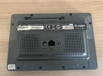
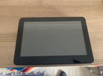
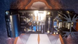
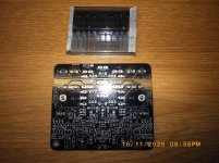
Tortuga Audio's latest offering is the LDR.V25 Preamp Controller together with a 256x64 pixel white-on-black graphical OLED display module with encoder and apple remote. This is our 4th generation design. We use this same hardware in our commercial preamp product line.

The firmware is mature at this point with occasional minor bug fixes and/or tweaks but will remain proprietary hence we don't share the source code. The V25 runs on an ARM Cortex M3 microcontroller and is programmed in C. Updated hex code files can be downloaded from our website and uploaded into the controller by the end-user.

As a standalone passive preamp the V25 sounds great. You can also incorporate it into most any new or existing solid state or tube based active preamp with exceptional results.

Here are the highlights:

* 100 step volume control/attenuation over 60 dB range
* Muting with volume ramp-down and ramp-up
* Built-in self calibration of the LDRs - no LDR matching required
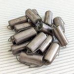
* LDRs are replaceable plug-in modules
* Can switch up to 6 stereo inputs with switching built into the board
* LDRs are also used for input switching in lieu of relays
* Mono/stereo mode controllable via remote
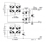
* Use a pair of V25 boards to handle balanced audio
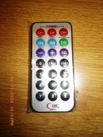
* Fully remote controlled via any silver Apple remote with remote ID pairing (256 remote ID's possible)
* Adjustable input impedance between 1-99k ohms | up to 10 possible settings (#1 is 20k fixed default)
* Firmware can be updated via simple PC based bootloader program and USB cable
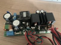
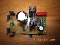
* Powered by most any DC source between 9 and 30 volts DC rated at 500 ma (actual demand is considerably less)
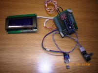
* 256 x 64 pixel graphical OLED display with interface board with mounted IR receiver module & encoder attachment point
* OLED attaches to the V25 board via a 14 pin ribbon cable which carries power, OLED, encoder and IR signals.
* Menu driven OLED display with numerous functions including
* Turn preamp off
* Control volume
* Adjust left/right channel balance
* Switch inputs
* Adjust display brightness
* Adjust display timeout (blanking)
* Change max initial volume on startup or input change
* Change units between steps & dB
* Show firmware version
* Adjust impedance & update calibration
* Reset (all impedance/calibration data)

When purchased together as a package, the LDR.V25 (equipped for 3 inputs) plus OLED display/encoder run $399.

With few exceptions, we ship most anywhere in the world.

Here's a link to the LDR.V25: LDR V25 Preamp Controller | Tortuga Audio

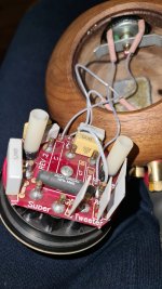
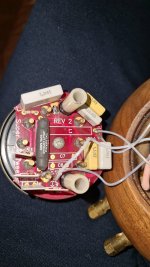
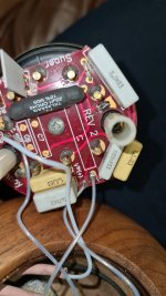
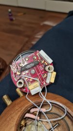
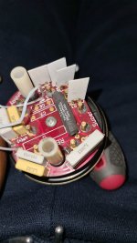
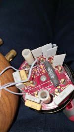
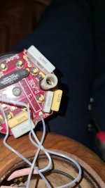
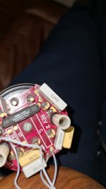
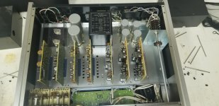
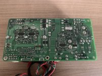
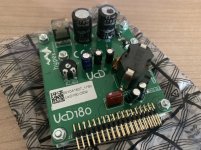
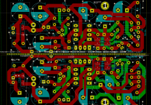
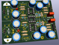
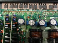
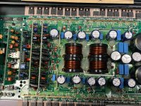
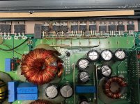
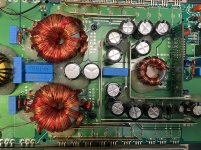
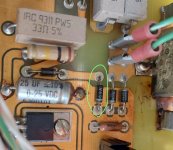
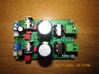
This pic of the V25 shows the Rev A version. We are now on Rev C that looks almost identical has a few parts moved around. The Rev C board switched to SPI communication with the OLED rather than the earlier 8 line parallel method.
An externally hosted image should be here but it was not working when we last tested it.


An externally hosted image should be here but it was not working when we last tested it.


The control menu has changed slightly from the one shown below. The Impedance and Calibration items have been merged into a single Imped-Cal menu item since these are so inextricably linked functionally.
An externally hosted image should be here but it was not working when we last tested it.

LM1875 in parallel configuration and used in a composite amplifier.

Chris and others have put great effort into improving amplifiers based on the LM1875 chip. The results achieved are very promising but evidently limited by the moderate current capability of the LM1875 chip.
In order to overcome the limited current handling of the LM1875, it has been discussed to design a version with more LM1875 operating in parallel such that the current handling is increased. A parallel version may allow for a BTL configured version based on LM1875s with an output power well exceeding 100W. As a last feature, it has been envisaged to use an OP-AMP controlling loop for a composite amplifier design. Composite amplifier designs can achieve very low THD values.

For a start it is foreseen to progress as follows:

a) Discussion of principles and design details, initially of a parallel LM1875 amplifier.

b) Establishment of a design for a parallel LM1875 amplifier.

c) Construction and test of such a parallel LM1875 amplifier.

d) Design of an OP-AMP control loop for the parallel LM1875 amplifier in a composite amplifier configuration.

e) Construction, test and trimming of the composite amplifier.

f) Construction of a similar composite amplifier for a BTL configuration.

g) Test of the composite BTL configured LM1875 amplifier.

h) Eventual PCB layout for those interested.

Anybody is evidently invited to take part, actively or more passively, in this project. It is obviously an objective that the project will end up in a high performance amplifier. But beside that aim, it is hoped that the process will show to less experienced diy’ers what considerations and methods are part of an amplifier design. It should be kept at a level were most members can follow the discussions.


:wave2:

FS: β24 Power Amplifier

FS: β24 Power Amplifier (shipping & insurance incl'd!)

β24 Fully-differential Power Amplifier

Built in 2010, it served me very well. My build accepts XLR or RCA, using the included cables. This was an extremely fun and rewarding build. The power-indicator LED is green. The amplifier itself weighs approximately 50lb.

PRICE: $1300 shipping and insurance included via FEDEX to anywhere in the continental US

FREEBIES:
XLR-XLR cables (Blue Jeans Cable), XLR-RCA cables, hospital-grade power cord.

LOCAL PICKUP:
Dallas TX. PM me about details of a discount for this option.

This is also listed on head-fi here, where I have a lot of feedback.

286727d1367035148-fs-24-power-amplifier-86187ed8_dsc_0146.jpg


286725d1367035148-fs-24-power-amplifier-3dfd2316_dsc_0152.jpg


286726d1367035148-fs-24-power-amplifier-306c516a_dsc_0158.jpg


286728d1367035148-fs-24-power-amplifier-ae87b5b7_dsc_0138.jpg

Attachments

  • 3dfd2316_DSC_0152.jpg
    3dfd2316_DSC_0152.jpg
    26.4 KB · Views: 1,548
  • 306c516a_DSC_0158.jpg
    306c516a_DSC_0158.jpg
    66.9 KB · Views: 1,063
  • 86187ed8_DSC_0146.jpg
    86187ed8_DSC_0146.jpg
    43.4 KB · Views: 1,104
  • ae87b5b7_DSC_0138.jpg
    ae87b5b7_DSC_0138.jpg
    60.8 KB · Views: 1,139

Troubleshooting occasional woofer flapping

I tried to look up the symptoms on here and the internet but I'm not sure I got the right answer. Here's the setup & the symptom.

5.1.2 surround speakers on a Marantz SR8012 AV Receiver, stated 140watts per channel at 8ohms.
Polk TSI300 floor standing speakers with 5.25" woofers, rated to 150 watts handling each at 8 ohms. Bi-amped to 2 channels from the Marantz for each speaker, I'm assuming I bi-amped them rather than bi-wiring.
Crossover set at 80hz with subwoofer, not sure at what order (1st, 2nd or 3rd), not much below 80hz should be going to these speakers.

The problem:
The woofers will flap loudly when watching certain movies that have very bassy audio tracks. It's very occasional, so not every movie does this. A movie like Blade Runner 2049 does it alot. It only happens on the floorstanding speakers, which are the only speakers in the setup that are bi-amped.

What I think may be happening:
Since the marantz is putting out 140wpc, and I've bi-amped 2 channels to each floorstanding speaker, I'm assuming that I'm overloading the woofer coils with too much wattage. If the whole speaker (2 woofers, 1 tweeter) can handle 150 watts, then maybe by bi-amping it can only handle some of that when you send 140 watts to the tweeter and 140 watts to the woofers.

What I'd like to know:
It only flaps during extreme bassy moments in some movies, and doesn't make bad sounds otherwise or when playing music so is it possible I'm exceeding tolerance but haven't damaged the speakers yet? What do you think is happening? Is it likely that I've broken them or not? I've read that it's better to have a higher RMS per channel amp with a lower RMS speaker than vice versa because sending low-wattage overdriven amp signals to hi-wattage speakers can damage, isn't that true? Should I be fine if I just don't bi-amp these speakers and rather send one channel to each?

Audio mixer repair advice

Good day all.

i purchased a 12 channel mixer and when i tested it, 4 channels were not passing any audio signal to the master out.
i opened it and tested the opamps using a multimeter and found that on the 4 defective channels, the side of the opamp that faces the mic and line sockets showed 15v on the +\-input pins and the output while the other side showed 0v. let me also state that i tested power supply and its fine.
all other opamps on these channels are working fine.
i switched out an opamp on one defective channel for a new one and tested. still no signal and the 15v was still there on the opamp pins.

i am seeking further help on repairing it.

thank you in advance

Transconductance Amplifier Question

Hi folks,

One of my amps has the following written in its description - “Single Gain Stage Transconductance Amplifier.”

Now, it’s been in my system for a couple of years, and just now started to read its literature (thanks to Covid). I’m not exactly technically savvy, so just wanted to know in layman’s terms if it really means something usable, or just another bulls@it audio-expression.

I know Pass’ First Watt stuff also called transconductance amps, but not sure if the principle is the same comparing to my amp.

The device in the question is Audio Analogue Donizetti Anniversary.

Appreciate your input.

Waveguides and compression driver exit angles

I'm considering starting a project with waveguides, after listening to erjee's http://www.diyaudio.com/forums/multi-way/195870-el-cuerno.html and keyser's http://www.diyaudio.com/forums/multi-way/192737-2-way-waveguide-cardioid-like.html .

I think it was Dr. Geddes who mentioned a couple of times that compression drivers have a certain exit angle. I think 6 degrees was mentioned for B&C drivers.

This angle would be relevant for the coupling with the waveguide, I suspect 🙂 . So is there a standard angle, or does this vary among brands? Could I combine an 18sound waveguide with a Beyma compression driver, for example?

Thanks! 🙂

Three functions for a Mosfet: CRC Filter, Soft Start and i-sense. Will it work or not

Features:

- 270VA Toroid
- 60Hz line
- Output from 1 to 30v with maximum current of 7A
- adjustable current control
- use of the LM723
- filter capacitors: 4700uf and 22000uf

I imagine a single Mosfet, using its Rds resistance as an integral part of the CRC filter and as a shunt resistor for reading current. Also using as a soft partial start.

Well, for a cut frequency of 50Hz, the calculated resistance was 0.14R. I have the IRF6218 which has the Rs = 0.15R.

What are the possible problems that I will face with this configuration?

Lm723-Lab2.png


Update #16

StartSoft_6218_2.png


Update #32

Diy_lab_723_v4.png


Update #41

pcb_723_3d_2.png

problems with my vented full range design (Tang band W5 2143)

Hi, i am new here and new to making speakers though i've worked as a producer mixing engineer for over 10 years.

Now i have decided to design a small pair of speakers based on the Tang band W5-2143 . I've calculated everything on WinISD to get a 9,3liters box with a tuned frequency of 57hz and a vented port of 20x112x230mm.

The problem is that the speaker behaves the exact same way than closed and when i measure the inside of the vent i am getting a boost at around 100hz and not close to the "tuned frequency of 57hz"
The vent is places in the left side of the speaker at the bottom.

Now the box is a little odd because i want it attached like a frame on a wall :
interior dimensions are 262x262x150mm and i am using 19mm mdf which makes it 300x300x186mm

Anyone has any light to shine?
My next try will be to do a round vent. see where that takes me...

Thanks
Manu

SSHV2-P.C.Bee V4 Mosfets-ES9018K2M DAC-LT3042 DIYINHK-PSU+3/5/7V- Controller ES9018K2

SSHV2-P.C.Bee V4 Mosfets-ES9018K2M DAC-LT3042 DIYINHK-PSU+3/5/7V-Controller ES9018K2M

1. Pee Cee Bee V4 Two board plus 4 selected Mosfet 2x ECX10P20 2x ECX10N20 55 euro plus ship..SOLD
2. ES9018K2M DAC Isolated with ELNA Audio Cerafine 100uf/10V made in Japan with LM opamp. 30 euro plus ship..
3.0.8uV Ultralow noise DAC power supply regulator +3/5/V, 1.A LT3042 DIYINHK 35 euro plus ship.. Sold
4. PSU type D Reflector +3/5/7V 4ΧMUR 860, Μain Cap 10.000uf/35V Panasonic , Panasonic 1000uf/25V Low ESR, WIMA 0.22 uf MKP 35 euro plus ship..
5. Controller for ES9018K2M DAC 45 euro plus ship...
6. Salas SSHV2 with XTP08N100D2 IXYS SOLD

Attachments

  • SSHV2.jpg
    SSHV2.jpg
    98.2 KB · Views: 1,203
  • IMGP0027.jpg
    IMGP0027.jpg
    988.6 KB · Views: 1,137
  • IMGP0028.jpg
    IMGP0028.jpg
    981.5 KB · Views: 1,115
  • IMGP0029.jpg
    IMGP0029.jpg
    987.1 KB · Views: 1,073
  • IMGP0030.jpg
    IMGP0030.jpg
    815 KB · Views: 1,048
  • IMGP0031.jpg
    IMGP0031.jpg
    1,012.5 KB · Views: 478
  • IMGP0034.jpg
    IMGP0034.jpg
    922.6 KB · Views: 446
  • IMGP0043.jpg
    IMGP0043.jpg
    545 KB · Views: 371
Projects by fanatics, for fanatics
Get answers and advice for everyone wanting to learn the art of audio.
Join the Community
507,757
Members
7,887,059
Messages

Filter

Forum Statistics

Threads
406,167
Messages
7,887,059
Members
507,757
Latest member
jossdorn