New cabinet, same drivers/amps worth it?

Hi,

I recently built a pair of 4-way sealed speakers with 4 mid-level Scan-Speak drivers (TMWW) and a built in Dayton Audio sub driven by two Hypex fusion amps (122+252) per speaker. The cabinet is MDF with minimal parallel walls inside, decent bracing, 3' radius curves on the front and manufacturer recommended volumes. They sound really good to me, especially the tight fast bass.

But of course you always want to see if you can do better (and I love the whole design process). So I'm wondering if I can build a different cabinet for the same drivers/amps and hear a noticeable improvement.

There aren't many things I think I can really improve but there are some:
--Move the sub from the back to the front so it is further from the back wall (7' vs 5') and firing directly at me
--elongate the woofer chambers to reduce back wave reflection
--strengthen/double or increase damping/bracing on the MDF walls
--I could buy one more midrange per speaker and go to D'Appolito configuration, possibly moving the woofers from being together by the floor to being in an WMTMW config
--move from large baffle (currently 15" including 3" radius on the sides) to narrow baffle around the MTM
--I could conceivably move to rounded walls on the sides and back but probably wouldn't (as there doesn't seem to be consensus on whether that is necessary)

Here are pictures / plans of the existing build

front.jpg

back.jpg

plan front.png

plan back.png

Does anyone have experience suggesting it is worth it, or does it really come down to the drivers/amps as long as they are in a decent enclosure (especially given I don't have an anechoic chamber to get perfect measurements)? Just looking for some views

Monoblock amps with a subwoofer

Hi all.
My first post here, so please forgive any unwitting transgression of the rules written or unwritten. I’m also hoping this is the correct forum. I appreciate its about a subwoofer but the issue feels more like an amplifier one. Please feel free to set me straight on any of the above.
So preamble over, here’s the issue:
A friend of mine is trying to connect a single subwoofer to two monoblocks. The high level connection to the SW has three leads and in his stereo amp, with common negative terminals, it is quite happy connected to separate left and right +ve and a single -ve terminal. With the monoblocks, this setup immediately kicks in the power protection circuits on both amps. Conventional wisdom, other forums and the SW manufacturer all state that you can’t do this and two subs is the only option. The problem is these things are £2.6k each and occupy a significant volume of his lounge. So while he would consider buying another one, he’d sooner not just now.
As I see it the issue is that both amps are somehow being connected inside the subwoofer’s amp and the fact that their -ve lines are not connected is producing an imbalance. My thoughts are that if I can isolate the two channels from direct contact with the sub’s amp before they are combined then the problem should go away. With apologies for the crudeness of the diagram, the attached is a suggestion for using two isolation transformers to decouple the monoblocks from the sub, while allowing the signal to pass through.
Thanks in advance to anyone who can spot the school boy error(s) I’m sure are lurking in this somewhere. If it works, I can’t believe I’m the first person to think about it.

Cheers
Alan

Attachments

  • isolation transformer for Subwoofer.jpg
    isolation transformer for Subwoofer.jpg
    60.8 KB · Views: 371

Mundorf AMT D23 1.1 pair

I’ve got a nice pair of Mundorf AMT 23 D1.1 tweeters that I purchased from a speaker designer friend for a project that never materialized. As you know, these AMT’s are crazy expensive but supposed to be the best of the AMT’s. Asking $300 plus shipping for the pair. Located in the US. Please ask any questions.

Attachments

  • CF8698CE-8520-4DAF-9445-33ED138DFF88.jpg
    CF8698CE-8520-4DAF-9445-33ED138DFF88.jpg
    764.9 KB · Views: 170
  • 13BBFF48-FFDC-4908-99FD-B9CA98ABFC5F.jpg
    13BBFF48-FFDC-4908-99FD-B9CA98ABFC5F.jpg
    738.4 KB · Views: 141

Complete set of parts for Ultrasonic RCM

I purchased all the parts to build an ultrasonic record cleaner but bought a Glass Audio Desk instead.

The spindle and record separators are made by a good member on Audio Karma who sells them as Record Rotisserie. The quality is superb. I also bought the recommended ultrasonic tank and drive motor. All you need to finish is a mount for the motor and spindle assembly. There are lots of photos showing various ways to build this.

I think I paid over $400 for all this stuff, so how about $200 plus shipping. If this is too high or too low, please feel free to make an offer.

Thanks for looking.

Attachments

  • DSC_5513.jpg
    DSC_5513.jpg
    457 KB · Views: 130
  • DSC_5515.jpg
    DSC_5515.jpg
    614.1 KB · Views: 133
  • DSC_5516.jpg
    DSC_5516.jpg
    592.3 KB · Views: 137

Frequent on/off switching of quartz crystal oscillator

Maybe another stupid question . But I think some of us use IR-remote control to control our diy audio equipment , I certainly do.

I'm making IR remote control with HT12 D & E . I can source these easily in country.
But only the enocoder HT12 E , not A version that has a 38Khz output to drive IR led's. No problem , I just add a 38Khz oscillator and gate it with the positive data output. It works , but the RC oscillator frequency is strongly related to the supply voltage.
With 2 AAA's that is 3.2 V to 2.2 V near empty. So the RC oscillator is just not posible.
Only way I see is like in most RC's : 455Khz resonator + divided by 12 , which is a bother an too many more components (counters/gates).
OR a 38Khz QXtal , like Mouser has (38.4 Khz ) paired with a AHC1G or even an AUP1G nand or nor gate.

First version in pic , works with RC oscillator , it gets switched on and off with EVERY bit of the 3khz data output data , just not doable with a QXtal.
Second version in pic , the oscillator starts when pressing a button on the remote and only as long as the button is pressed . The AND gate modulates the 3Khz data output with the 38,4 Khz from the QXtal.

Here's my question :
Is a quartz crystal ok for this often on/off switching ? Will it shorten it's life ?
A RC oscillator has of course no problem with it , but a QXtal is different.

And : A RC oscillator like here with SchmittTrigger gate , starts immediately , first period is slightly longer . How quickly does a quartz ocsillator start ? Is there a a short time that the frequency isn't right yet ? In that case I need to start the transmission a little later from when the button is pushed.

I have no oscilloscope , so I can't check for myself.
Thanks !

Attachments

  • 38,4 Khz QX-oscillator.JPG
    38,4 Khz QX-oscillator.JPG
    36.6 KB · Views: 296

DIY AMT Headphones

Inspired by the HEDD AMT headphones, I thought I'll make pair of my own.

It'll be a slow start for sure; I have other projects that needs to be finished first.

I'm not a novice when it comes to DIY AMTs, although this AMT will have different pleat depths in order get a decent bass response together with mids and trebles.
To get that right will definitely be a challenge.

Other challenges are the weight, HEDD's headphones weighs over 700 grams, and the comfort.

So, any initial thoughts?

Peerless 1.25" corundum dome tweeter + crazy idea.

Hi,

I am an old home speaker builder from the 1970s and 80s who has not built anything since 1992, before the easy availability of all the home speaker computer programs. I was thinking of building one last pair of speakers just for the heck of it. A company called Spatial Audio has a crazy loudspeaker design called the M3 Sapphire. It uses the well regarded Peerless 1.25 inch corundum dome tweeter in an almost crossoverless design using just a 33uf capacitor in series with the tweeter. This large cap allows the tweeter to run down to its resonance frequency near 600hz. The company owner told me that the M3 Sapphire could play comfortably to 90db, but he did not specify room size or give a power rating for the loudspeaker in watts. He mates the tweeter to two large woofers in an open baffle design.
Spatial Audio M3 Sapphires - MyAudioPhrenia

My crazy idea is to try to mate the same tweeter with a single 33uf cap to a 8 inch diameter Peerless 830869 8" Nomex Cone HDS Woofer, with just a 2.5 mH coil in series with the woofer to simulate a 6db per octave crossover at 600hz. I would put the woofer in a 9.5 inch wide, 11 inch high, and 12 inch deep cabinet made of 3/4 inch thick MDF and covered in Formica. The tweeter would be mounted on a separate home made MDF stand and placed on top of the woofer cabinet in an air mounted, minimum diffraction design that is cushioned from vibrations by a foam pad. So the idea is to end up with a pulsating hemisphere with a range from just below 600hz to beyond 20,000hz mounted in free space on top of a pretty mellow and fast low q (Qts .31) 8 inch woofer in a sealed cabinet with a Qtc of about .9. I would use the speakers as satellites mated with two subwoofers at 80hz or so. I know it sounds like a crazy stupid idea, but it just might work. If Spatial can get away with using the tweeter almost full range, then anyone should be able to do it. I do not listen to loud music anyway, so it could work for me and would be easy to put together. The woofer and tweeter have very close sensitivity ratings, so there would probably be no resistor compensating network needed, just one cap and one coil per speaker. I would appreciate comments, suggestions, etc. See detailed specs below.

Peerless DA32TX00-08 1-1/4" Corundum Dome Tweeter
8 ohms, Re 6.78 ohms, 89.78dB 2.83V/1m, Listed at a whopping 120 Watts RMS! Fs = 573.04Hz
https://www.parts-express.com/pedocs/specs/264-1678--peerless-da32tx00-08-spec-sheet.pdf

Peerless 830869 8" Nomex Cone HDS Woofer
8 ohms, (Re) 5.9 ohms, 90.2dB 2.83V/1m, 60 Watts RMS - 150 Watts Max.
https://www.parts-express.com/pedocs/specs/264-1098--tymphany-hds-p830869-spec-sheet.pdf

Driving a mosfet follower with a tube

I presently work in a Melos SE75 single ended with 6Kg6 output tubes
Each output tube is driven by a BUZ80 mosfet follower. The first stage is a 12AU7 in cascade with 20K plate resistors. There's even a mosfet follower between the two cascaded 12AU7. (???) The last 12AU7 is driving a BUZ80 mosfet follower which drives two paralleled BUZ80 driving two output tubes. As I think that the mosfet follower between the cascaded 12AU7 is overkill, I bypassed it. The BUZ80 has an input capacitance of 750pf. This is probably why the 12AU7 is driving one BUZ80 who is driving two BUZ80 instead of driving directly two parallelled BUZ80. Do a 12AU7 with 20K plate resistor could perhaps drive 1500 pf ? Thanks.

DIY hot mod v2

Hello . I start again the topic hot mod v2… for those who do not know what this is. we replace the second lamp on a marshall (jcm-jmp) with it and it gives the amplifier an extra gain stage without disturbing anything inside the amplifier circuit. this was pre-made by mike soldano and was called hot mod. where it was an adapter with a 6C10 lamp which has 3 triodes instead of 2 that the 12ax7 has ..but the 6c10 stopped being produced and so the hotmod stopped coming out… in recent years the hotmod v2 has come out which is an adapter with two 12ax7 lamps ..for this there is no schematic on the internet, but there is for the first hotmod .. observing the first plan we see that all 3 triodes are used .. now the trick is more?!?!. we will use a 12ax7 lamp for the first 2 triodes and another 12ax7 lamp for one triode (but half) .. the issue is this, we have 1 triad left, how could we use it? in the drawing below I show the schematic of the hot mod v1 and the schematic of my own…6775723E-7A82-4656-8CD3-FBA48E314BA5.jpeg

5D189656-AEAA-4DEA-9A79-B0E65B674EB4.jpg

05EF792D-E9B9-4680-BB1F-87D78D537B76.jpeg

C73AFEAC-B628-4337-A40B-A464EE60BF35.jpeg

Jcm 800 2204 Marshall + mods

Hello to the forum … in a little while I will finish my project with the 18watt Phoenix (dr Z carmen ghia). I am waiting for some things to come to me and I even thought of getting ready for the next project which will be Marshall jcm 800 2204… I have some questions and I would like someone who knows to help me. first of all I would like to explain that this project will be very high gain than the factory one, that is, I will use some mods that I found .. but beyond that I have the following questions:
1) transformer high voltage wires . I have seen several schematics which differ from the high voltage ones. some are 650 vac some are 640 vac some are 690 vac and some 694 vac .. which of all is the right one for high gain?

2) about mods . I found this page on web for Marshall jcm 800 2204 mods . And I don’t understand the 1st of mod that say : 1. Locate the 68K input resistor (R3) and place a 330pf 1kv ceramic cap across it. This will beef up the mids and lows and make the entire amp feel more "meaty" and "thick".

I don’t understand that : and place a 330pf 1kv ceramic cap across it,, it’s mean parallel with R3 or after R3?

For now I have only these questions .. thank you C318CBBB-2497-4574-B48C-48DCE72243B3.jpeg0C81D9C9-6686-4A02-9742-BAA933702C06.jpeg38A87D5B-7A0E-40B4-BDB0-1DFBA17F92AA.jpeg391FAC6F-A30D-4484-98CD-8EC0F83E7F94.jpeg993A73C5-E706-48BA-B28F-5F1703259089.jpeg

can you help me a bit with car amplifiers?

Hello, I'm a beginner in diy audio, I want to build a relatively small and as powerful as possible two way bluetooth speaker. With speaker specs it's all pretty much clear to me, but I'm having a bit of a trouble with car audio amplifiers. If I wanna have one subwoofer and 2 tweeters (3 speaker units overall), do I need a 4 channel audio amplifier? And also, is it fine if I buy something like a 1000 or even 5000w car audio amplifier? I found these quite easily available to me for a decent price, my concern is, won't an audio amplifier that powerful overpower the speakers or something? I'd put something like a 200w or 300w subwoofer into the speaker enclosure.

TDA8954 output filter

Hello

i am busy with a TDA8954 PCB.
the TDA8954 looks like a fairly easy IC for a high power amplifier.
PCB design should work out, PCB will be professionally made in china (so cheap 😀)
but one thing bothers me, the output filter, especially the inductors.
i can imagine these should be able to withstand some serious currents.
i want to make a stereo amplifier for 4 ohm speakers, so roughly 200 watts per channel.
but a classmate wants to make a BTL version of it (8 ohm 400 watts)
what coils are good for this kind of currents?

when looking trough the coilcraft site i found two types look promising:
Coilcraft PCV-1 Vertical Mount Power Chokes
Coilcraft VER2923 High Current Power Inductors

would one of those types be good enough to handle high currents and have decent audio performance?

datasheet TDA8954:
http://www.nxp.com/documents/data_sheet/TDA8954.pdf

Rik

Sony CDP C325M ribbon cable

Hi all, does anyone know where I might source a replacement flexible ribbon cable for a Sony C325M 5 disc CD player. It is the cable that connects the laser assembly to the main board. They are hard to source it seems. Mine has intermittent connectivity at one end where it has been flexed too much resulting in solder breaks. The cable has 18 contacts at each end but one end as a gap between two of the contacts which makes it one connector wider than the other end. I can post an image if need be and also supply the part number stamped on the cable. I realise that I could hard wire the laser to the board but that would mean 18 pieces of wire need to be soldered. Glenn

What's the point of working with untrustworthy data?

I don't build cabinets for a number of reasons. Let's face it, commercial cabinets are far better looking. So, I'm looking for a 20 litre cabinet to house my 8" sub and I stumble across a JVC that matches my decor.

The original specs for the system don't matter to me. I just want the box. However, I was astonished by JVC's claims: Frequency response: 30Hz - 20Khz. SPL 77dB. A mouse can fart louder than that.

I can only conclude that JVC are one of the few manufacturers telling the truth. i.e. at 30hz output is 10dB down. As quoted T/S parameters are + or - 30% what is the point of using them?

Attachments

  • jvc sub.jpg
    jvc sub.jpg
    20.8 KB · Views: 214

FS: Tokin THF-51S NOS Matched Quad

FS: Tokin THF-51S NOS Matched Quad

SOLD !
I bought these from watanabetomoaki.
He listed them categorically "PRECISELY Matched Quad (4PCS) of THF-51S (with curve tracer data) TOKIN SIT FET"

They are NOS, never used, in excellent condition. Comes with his original packaging, curve data sheets and invoice. See pics.
I don't want to sell them... But need to raise funds to move and start a new job in New Orleans area.
$400. plus $9.85 Priority shipping. US lower 48 Only.

Charles

Attachments

  • IMAG0074.jpg
    IMAG0074.jpg
    37.6 KB · Views: 339
  • IMAG0076.jpg
    IMAG0076.jpg
    39.2 KB · Views: 349
  • IMAG0078.jpg
    IMAG0078.jpg
    36.9 KB · Views: 337
  • IMAG0079.jpg
    IMAG0079.jpg
    41.8 KB · Views: 332
  • IMAG0080.jpg
    IMAG0080.jpg
    35.4 KB · Views: 336
  • curve.jpg
    curve.jpg
    27.5 KB · Views: 103
  • curve1.jpg
    curve1.jpg
    29.5 KB · Views: 88
  • curve2.jpg
    curve2.jpg
    30.2 KB · Views: 84
  • curve3.jpg
    curve3.jpg
    29.8 KB · Views: 72

Help needed: interfacing uProcessor with tube amp

I'm in the planning stage to make a microprocessor monitor (and
possibly bias controller) for a tube amp. I have a good understanding
of tube amps, microprocessors, and code, but solid state electronics
is a gap in my knowledge. I'll probably use a Teensy, because they're
cheap, easy, and there's lots of easy to work with peripherals (it is
arduino compatible).

For the first iteration, very simple, I would only be monitoring the
bias at the output tube cathodes. The amp would be shut off via a
relay if the bias current on any tube went too high or too low.
Second iteration, I might want to detect the presence of a music
signal, shutting the amp off if idling too long (e.g. an hour or so).
The third iteration, if I go that far, would be controlling the bias.

So the part I don't know much about, is what are the considerations
for interfacing the processor with the amp? First, the ADC input will
need to be protected from overvoltage. I'm not sure simple Zener
clamping will be sufficient. Is there some sort of failsafe chip
available that will limit a voltage to 3.0V or so (assuming 3.3V
processor supply).

Second, I'll want to filter noise in both directions. For a current
sense resistor on a cathode, maybe some sort of buffer device,
followed by a pi filter. For bias checking, the low pass could be
below 20hz, but for detection of signal it would need to be higher.
Some of the low pass filtering of the detected bias current could be
in code rather than hardware.

For bias control, I think a digipot would be suitable, noise filtering
would be the only issue.

The processor would of course be in a shielded metal box, and might
also be external to the amplifier.

Thanks in advance for your thoughts.

Through holes can sometimes make a PCB "unrepairable"

I've been doing a lot of PCB boards lately and I've found that the over-use of through holes can make some parts unsolderable. Namely parts that have many pins and don't give any access to the top side of the board, terminal blocks, relays, some tube sockets, etc. I've found that through holes make it real easy to do routing, but for parts that have many pins Its better to use one-sided bottom pads wherever possible. When you solder a through pad some of the solder "mushrooms out" on the opposite side under the part that has many pins and is tight against the board. So removing such a part later is nearly impossible even with a solder sucking iron, you cant wick that mushroom cap under the part either. And the solder sucker doesn't suck out the mushroom cap on the other side, so the pins are basically trapped. Adding to the unsolderability is that you can't pull one pin at a time, you'd need to melt all the pins and pull the whole part, try doing that with a 8 pin relay. Now this problem doesn't happen with unsoldering two leaded parts, you just melt and yank, easy, then clean the pads and install the new part.

I'm having to revise some of my boards to limit the use of thru pads under multi-pinned parts that hug the board, to keep them repairable in the future.

Just thought I'd pass along this observation.

perfect break connection of the power drop

Hi . There is a task to ideally (from the high-end point of view) connect the cable going to the equipment and the cable coming from the power supply (lacquered stranded copper).
1. Soldering - contact may change resistance.
2. The twist may oxidize (+ the varnish must be removed ideally) ... perhaps such a connection will become a "step" for the current to move.
3. Crimp the Pin tube (the wire may oxidize over time inside the tube)

What thoughts do you have? - I repeat - you need the highest quality, repeatable connection that will not spoil the quality of the power supply.

Any decent way to improve the RCA jacks on the Hafler DH-110?

I have a Hafler DH-110, and as is fairly well known, the RCA jacks on the back suck. I've resoldered a couple that I couldn't fully plug in to, but they are still super tight on my smaller RCA plugs, and my bigger plugs jam in the recessed case panel.

I'm looking for anything I can do to produce a solid improvement, at least for the commonly used plugs. I could source new panel-mount plugs and simply replace like-for-like with better metal. Ideally I'd like something that can mount to the panel directly and provide more secure plug/unplug action.

I'll take any thoughts or ideas.

Attachments

  • IMG_3179.jpg
    IMG_3179.jpg
    921.5 KB · Views: 279
  • IMG_3182.jpg
    IMG_3182.jpg
    933.8 KB · Views: 270

Discrete opamp OP1005.1A

Because of an interest, here is the project.
The zip file is in two parts.
Of the file: op-1005.1a.z01.zip
remove .zip
Become the name: OP-1005.1A.Z01

Attachments

  • Like
Reactions: Brijac

Found some old parts and want to build something

Hello all! I recently found some old transformers and I am looking to build something from them. Id like to build a couple mic pres based on the Mastering Labs ML-1 but that is just a baseline. Here is a list of the parts i found. If anyone has a schematic, diagram, layout or idea of how to create something cool from these parts I appreciate the info. These items are NOT FOR SALE. Thanks for the help and ideas! Looking forward to making something cool!

Parts List:
1 - UTC LS-56
2 - UTC LS-10X
2 - UTC LS-141
1 - Triad HS-66
1 - Jensen JE-11S-L
10 - Beyer Dynamic 351
6 - Freed 32035
1 - Freed 39940
1 - Freed 39811
1 - UTC A-24
1 - UTC A-39
2 - UTC A-10
2 - Hammond 850Q
1 - Hammond 850N
1 - Sescom MI-29

Mosfet for Bias control in ARC VT200

The bias on a bank of 4 KT88 is running away and causing red plating or worse-blown KT88's.I've checked all voltages and resistors going into the MOSFET. Coming out should be -80 but I'm getting -100vdc.Bias is running away and no where near stable.I'm looking for a drop in replacement since ARC wants me to send the amp in for repair instead of selling me the replacement parts.All I know is it is a NPN enhancement mode circuit.Any help and suggestions would be greatly appreciated. Q6-Q9

Attachments

AMIGA MT vs 2.5 CA18RNX

Hello,
I am about to upgrade my audio setup. I did a pair of SEAS MIMIR 10 years ago that I want to change for a floorstander.

Here you told me that Troels Gravesen designed a floorstander with the same woofers and (almost) the same tweeters than the MIMIR. All I have to do is to by a pair of new CA18RNX and build a (quite expensive) crossover.

The thing is that, as mentionned, my speakers are 10 years old and I whish my next project to last at least 10 more years. I am wondering if they could handle another decade?
While I was digging the internet I found Paul Carmody's AMIGA MT, so called "boutique HiFi killer". It seems to fit my needs with inexpensive speakers and crossover.


Talking about my needs: good response at low levels and with better kick and bass than the MIMIR. Price is also a concern as I don't want to go over 500€ with crossover and wood.


Do you see a clear winner between these 2 options?
Do you think that they could be powered by a TPA3255 amp?


Any advices/criticisms are welcomed!


Best

SE 304TL

making of :304TL SE - Google Drive
input on E80CC CF direct coupled to 6C45P-E nos bifiliar IT to 6BX7GT
+300/-280V CF direct coupled to 304TL
bias tuning from 6BX7 grids
best for tube life and sound quality 180mA @ 1200V
two set of 3X420V350mA smps in the lower 1U case
then two 5H300mA choke and two D-link dry 590uF1300V
50W A1 4ohm tap 8ohm load
THD1% @28W H3 -60db

Attachments

  • UP300_191228_1519 jpg.jpg
    UP300_191228_1519 jpg.jpg
    119.6 KB · Views: 688
  • 100_0122.JPG
    100_0122.JPG
    336.3 KB · Views: 703
  • 20191215_174017.jpg
    20191215_174017.jpg
    464.6 KB · Views: 655
  • 20191215_173848.jpg
    20191215_173848.jpg
    484.1 KB · Views: 659

Active crossover design : buffer and summation

Hello world!

For my mono Bluetooth loudspeaker project, I decided to DIY again an active crossover (my first home made was around 1992!). A Linkwitz-Riley of course!

1. My first question is about buffer.

From Mr Linkwitz himself, here is the way to go:
buffer.gif


Here is the Elliott Sound Products point of view::
elliot_sound_products_lr4.gif


What is the best design?
Especially if I need to add a pot volume before it.

NB: the source is a LQSC BT module. Amplifier: TDA7293 or LM3875 stereo (one channel per speaker). Independent power supply for crossover, amplifier and BT module.


2. For a different project, the second question is about source summation (subwoofer case) and crosstalk issue.

First example, I saw many time, summation before filter section:
LR4-2.gif

I assume RA & RB are involved in the cutoff frequency formula.
Is it correct?

Second example, summation after a stereo design with 2x10K resistors:
LR4-3.gif

Is it not a better way to avoid crosstalk?

Have a nice week.

Pierre

Marantz cd17 gold+remote

For sale cd player in top working condition with some fine scratches on the side panels, front is without scratches. On top cover is missing one screw. The player was upgradet with some verry good new capacitors from nichicon and on output with russian pio kbg mn. This was made from last owner.The player works perfectly and reed the cds without problem. The original remote is there. More info on privat mesage. Price is 100eu plus shipping.

Attachments

  • IMG_20211104_064136.jpg
    IMG_20211104_064136.jpg
    361.6 KB · Views: 170
  • IMG_20211104_064141.jpg
    IMG_20211104_064141.jpg
    595.2 KB · Views: 166
  • IMG_20211104_064147.jpg
    IMG_20211104_064147.jpg
    314.1 KB · Views: 160
  • IMG_20211104_064153.jpg
    IMG_20211104_064153.jpg
    351.5 KB · Views: 163
  • IMG_20211104_064207.jpg
    IMG_20211104_064207.jpg
    367.7 KB · Views: 159

What exactly is "standby" and does it matter for non-digital devices?

I understand with computers that standby saves the state of memory so that code doesn't have to be loaded from physical storage again. I could see this mattering for any digital-controlled component.

For an analog component, is "standby" a thing, and does it matter? I've seen "tube saver" circuits that lower the power level through the tubes when the amp is idle. Would disconnecting power to the output stage(s) but leaving the power supply caps charged up be a type of standby? Does it matter?

Recommendation for Capacitor "Cans" for Mark Levinson 333

Yesterday I posted the issue with my Mark Levinson 333 not powering up. I dismantled the unit and found one of the large capacitor "cans" (50,000uF/125V) to be leaking. Please see attached photos. This type (Cornell Dubilier) seems no longer available. Can somebody recommend me suitable capacitors for this unit? Considering the cost of these capacitors: Can I just replace one or do I need to replace all (2 per channel, total 4)?
Thanks!!

Attachments

  • IMG_4645.jpg
    IMG_4645.jpg
    773.3 KB · Views: 309
  • IMG_4646.jpg
    IMG_4646.jpg
    861.6 KB · Views: 279

Does any manufacturer have something similar to a Vifa NE19VTA?

I really wish I stocked up on these years ago. Anyway, something with the following characteristics would be really nice:

- compact form factor (mini flange)
- hard dome
- clean behaviour (relatively smooth and with a decent CSD)
- relatively good distortion down low
- not super expensive - looking you, SS beryllium tweets...
- no ferrofluid ideally

House maintenance... And beer. :)

Thread topic:
Just thought it would be nice to have a thread about stuff you've done around the house, and the important bit would be to take a picture of the completed job and a celebratory glass/bottle/can of beer (any kind, alcoholic or non-alcoholic, must be Beer, or wine or other type of fermented beverage 😉).
Small job or big, doesn't matter, as long as you're happy to be done with it and feel the need to mark the occasion. 🙂


We moved house almost 1 year ago, so many things we've had to get out of the way first.
The previous owner was not that good on work outside of the house, and I don't know who did the paint job on the terrace, but it's not good. The boards have not been painted or oiled in many years, and I've been peeling off paint on the top of the railing very easily with my fingers, because they used some rubbish acrylic paint, with no prepwork, on pressure impregnated wood.

This is the first time I can remember that I've been able to finish a task like this before Easter was over.
Yesterday I moved everything out of the way, pre-wash, wash with suitable detergent containing anionic tensides, scrub, 2 x rinse.
The floor boards completely soaked up 6 liters of linseed oil that I bought for the job last year, in two coatings. There was nothing left for the stairs (or top of the railing), but I found a small leftover of some kind of industrial "teak" coloured oil that was just enough for the stairs.

Good for the day, nice to have something cool to drink in the nice weather. Need more oil for the railing, and have to consider sanding it down properly first.

Attachments

  • IMG_20200410_152345_359.jpg
    IMG_20200410_152345_359.jpg
    539.2 KB · Views: 314
  • IMG_20200410_152406_225.jpg
    IMG_20200410_152406_225.jpg
    591.5 KB · Views: 312

PCB Procurement

Hi. My name is Steve and I am the Sales Executive for a PCB Procurement Company called JD Photodata. With over 30 years of experience we have established strong working relationships with both UK and Overseas manufacturers. From design to manufacture, inhouse inspection, and some of the cheapest prices you will find, let us look after your needs and take the strain out of purchasing. Prototypes, small runs and large runs, we can take care of all your needs. Free, no obligation quotes, scheduled deliveries for those larger orders with up to 12 months free storage.

Please feel free to call or email me to discuss any requirements you may have.
01462 452616 or

Power transformer and Choke effect on sound

I've built two TLSE amps, one for my wife with Electraprint outputs and Edcor PS and choke. The other one for me and had One Electron outputs and Edcor PS and choke. The Electraprints sounded a notch better than the One Electrons. I then changed my outputs to Hashimoto and they sounded better than the Electraprints. If I were to add Hashimoto PT and choke to my Hashimoto output amp, would there be a noticeable improvement?

Onkyo DX-710 ~ Power Transformer

Hello diyAudio community,
I was amazed by just looking in your projects as a guest a i decided to join the community and would like to do some diy myself.
I'm trying to mod the DX-710 that my father left me, i would like to change the power transformer and the old cd reader(player/lens) that is giving me some problems while reading the discs (skipping, rewinding).
I have so many questions.
Which characteristics do i need to look for the correct power transformer?
Can i replace the cd reader(player) to any other model or do i need to replace it from the same model? Should i be careful about which lens i'm going to buy for it?
I've found some toroidal transformers on aliexpress but i don't know if it's compatible with the Onkyo DX-710
This is the one i found

About the cd reader(player) replacement i haven't got any idea on how to pick the right one and i really hope with your help i will managed to replace it.
I can't just let it die

Thank you everyone for any help!

(Power Transformer Scheme)
power-transformer.png

Peerless LCPF600 first impressions..

Hi all,

I recently contacted Martin Helms, a very kind gentleman from Tymphany Company, upon a message I read on the forum and asked him for a sample of the LPCF600 module.
The amplifier is 3-channel and the power supply is embedded.
According to the data sheet; The amplifier is capable of driving 3 x 300W RMS @2ohm and delivers 0.02% THD for 1khz at rated power (0.003% for 1w). Also, the output noise is only 35uV. These values ​​seemed quite impressive to me.
Outputs can be configured as SE or BTL. This makes it possible to use the module quite flexibly.
Last Friday I received the sample (really fast delivery) and I started to examine the module.
According to my visual impressions, the amplifier is built on 3 pcs of IRS2092. There are 3 x 2200uF average quality capacitors per rail with symmetrical supply. Likewise, there is a medium quality capacitor after the bridge diode at the mains input. There is a two-stage mains filter at the mains input, which appears to be of good quality. There are also filters on the DC outputs consisting of two-stage common-mode chokes.
OPA1678 is used on the input stage (bottom surface).
The amplifier also has a debug module. With this module, you can easily perform on-off and mute controls. In addition, this module has status LEDs and XLR analog inputs.
The amplifier module can be easily installed and used.
I tested the amplifier with my DIY ES9018S DAC and Wharfedale Diamond 9.6 speakers. There was no preamplifier or volume control unit in between. Other than that, I did not use any special equipment, cables, etc.
As for my listening impressions;
I can honestly say I was quite impressed.
The amplifier has a very detailed and wide-stage sound.
Bass, mids and trebles were just right. (Diamond 9.6s are known for their lack of treble)
I did not observe any audible distortion.
There is no audible noise of any kind in both mute mode and play mode (with my ears sticked to the tweeters, even inputs were open; wow !)
I haven't done any electrical measurements yet. So I may add to my review in the coming days.
That's all I'm going to say for now.
I highly recommend you try it if you have the opportunity.

Drivers & Amps - Peerless

An Idea for a Controller for a Switched Flyback Transformer Power Supply

This is a theoretical post. Nothing has been made. This is also an uncertain post, which, is based on some myths, which, may or may not be true or may have an insignificant effect. However, some of the ideas may be used ( changed or not ) for Class D amplifiers.

Myths :

Because of lack of information, the proposed controller is made after some myths, made up by the author. Whether these myths are true or false is unknown.

Myths :

1. Continuous is better than discontinuous as far as the noise is concerned.

2. Gradual and slow switching of the primary is better than fast switching as far as the noise is concerned. Instead of the whole, suggested here, transformer, RC filters can be used before the transistor to allow slow switching.

3. Higher resistance ( Rce ) in series to a switching primary is better than low resistance as far as the noise is concerned.

4. Because noise can proliferate from the auxiliary and or primary coils through to the secondary coil ( s ), a controller, made with analogue, audio parts and without any component saturation is better than a controller, made with digital parts or non audio analogue parts or parts which can go in saturation as far as the noise is concerned.

The idea, therefore, is to make a flyback transformer controller with low noise, audio components, which, switches the control transistor of the transformer’s primary gradually and slowly within the period of the switching frequency of 50KHz to > 100KHz. The controller must perform a very gradual switch of the control transistor. This may or may not reduce the noise and may, even, increase the noise. Unknown.

Here is the document :

An Idea for a Controller for a Switched Flyback Transformer Power Supply - Google Drive

The schematics are in the addendum.

Bel Canto DAC, Beymas, & PureAudioProject Crossovers

I have a few things available to anyone interested.
I'll take any offer + the cost of boxing & shipping.

Also happy to trade for exciters.

Items:

  • Bel Canto 1.5 DAC (I don't have the original power supply but I do have one that works.
  • Pair of Beyma TPL150H drivers
  • Pair of passive crossovers from the PureAudioProject Trio15 Beyma.

ITEMS NO LONGER AVAILABLE.

Thanks to everyone for their interest.

Help identifying female jack connector

Hi,


Anyone recognizes the model/manufacturer for this audio jack?

It's a 4 contacts-TRRS type, no switch. SMD (L/R contacts, i.e. T and R1) and TH mounting (ground/mic contacts, i.e. R2 and S). Also comes with extra mechanical support in the form of a silver metal band with TH mounting to board.

It's used in quite a few digital audio players (Fiio, Cayin etc.) but after rather extensive search (Mouser/DigiKey/Arrow/Farnell/LCSC/Aliexpress etc.) I was not able to identify it.

Eventually (actually just a few mins before writing this) I think I think I may have identified the manufacturer (G-Switch - 轻触开关-防水轻触开关-TYPE-C连接器-TYPE-C母座厂家-品赞电子) and I even found a connector listed on their website that resembles very closely the one in question (PJ-0275S00 - 3.5四极6PIN带铜套贴片镀金耳机插座_品赞电子), however not the exact one I am after. Nor was I able to see one for sale.

I guess I'll reach out to G-Switch and assuming they reply will find a way to source a replacement for the connector I am interested in, however I thought it does not hurt to ask a question here as well. Thanks

Attachments

  • 20211107_172105.jpg
    20211107_172105.jpg
    877.1 KB · Views: 187
  • 20211107_172016.jpg
    20211107_172016.jpg
    532.9 KB · Views: 171
  • 20211107_172056.jpg
    20211107_172056.jpg
    596.2 KB · Views: 160
  • 20211107_172042.jpg
    20211107_172042.jpg
    467.8 KB · Views: 159
  • 20211107_172033.jpg
    20211107_172033.jpg
    464.4 KB · Views: 161

  • Locked
7 trillions dollars!

That is how much in the Fed balance sheet. I would think at some point it will matters. I suppose it already matters since people are paying more for everything. It's unprecedented in modern time. I don't think anyone really know how through which mechanism can the FED unwind its massive balance sheet. It is a bubble. Can the FED keep printing? Nobody really knows.

Modifying a Hitachi TRK-3D8E.. Ideas?

I have just been given this:

hitachi.jpeg

It's a Hitachi TRK-3D8E boom box / guetto blaster / brixton breifcase.

Whatever you call it, it sounds pretty good. It's powered by either mains, or what looks to be 8 x Alkaline size D cells, which would make it 12V.

Being that it's full of retro charm, I would like to modernise it's capabilities a bit, whilst retaining the retro look and feel.

Initial ideas are:

  • Different power source.. motorbike battery? Lithium cells?
  • Add bluetooth connectivity (or similar)
  • Add additional drivers - theres a LOT of space internally from what I can see though one of the vents
  • TPA3118 chipsets run on 12V....

There's an aux in on the back which I have been using with my phone and it works well.

Problems I have noticed:

  • There's a bit of hissing coming through - faulty equaliser sliders?
  • Cosmetically, it needs work!

I'm asking myself things like:

  • How much do I gut it?
  • Do I preserve things like the equaliser?
  • Could one of the tape decks make way for an OLED screen?
  • Charging circuitry for the batteries? (there's a switch on the back to choose AC/DC so it's not designed to charge anything)

I welcome any and all suggestions on what to do with this and how to go about it!

FS: Iancanada FIFOPi Q2, IsolatorPi, Raspberry Pi 3B [EU]

Up for sale here is:

1. FIFOPi Q2: like new, never been used because of the lacks of time to finish the project.
Price: 110€

2. Isolator Pi : very good condition
Price: 20€

3. Raspberry Pi 3B with OVP: very good condition, hardly used
Price: 20€

If buy 2 items or more, bonus one board of ShieldPi or I/V Std (bare board) & small discount.

IMG_20210730_220905658_HDR.jpg

Upgradng Yaqin MC-13S - Parts Questions

First, my appologies, I may not know the best formatting as I'm new to this forum, so I hope my post is functional enough. If not I'm willing to learn!

I have an audio repair person helping me with some upgrades for my Yaqin MC-13S. I am also getting started with DIY audio and am planning to try a preamp soon - but I'm not ready yet and I want my amp functional before the holidays 🙂 Also, I might not have gotten the specs right from my repair guy. I think I'm close, but looking for help there too.

The upgrades we are attempting are listed here... although the documentation is a bit sparse:

Yaqin MC13s Upgrades and Switchable Feedback Installed – AD Audio Consultants


An externally hosted image should be here but it was not working when we last tested it.


The quick version is that they made these changes:
Elna Silmic bypass capacitors,Mundorf ZN coupling capacitors, and Takman carbon film resistors, and a switch to disable negative feedback.

My repair person gave me the parts I would need, although I wanted to double check because he's ultra busy - and I want to make sure I understand as best I can.

1) Coupling Capacitors: .47mF 600v(or more) x 4
2) Bypass capacitors: 470mF 25v x2
3) Grid Resistors: 2w (or 3) at 820 ohms
First - could someone confirm this is accurate from this schematic:

Second I was planning on:

Mundorf Supreme SilverGoldOil caps
and Audio Note Silver non-magnetic Resistors (820R Ohm, and 2Watt).
Are these decent choices?


Thank you in advance for looking over and helping me.

Tube modeling/LTSpice questions

This is my first post here, so please be gentle. I've searched around the forums, and either the posts didn't exist or I am really terrible at coming up with the proper search terms(probably the latter).

First of all, my goal is to design and build a stereo single-ended tube amp from scratch. I'm a software architect and my electronics engineering extends, unused, back about 2 decades ago. The rust extends through the paint and most of the body, and is barely salvageable.

My training 20 years ago barely touched on tubes, mostly transistors. Finally, I'm trying to do my modeling on LTspice. I've seen mixed reactions to this on the forum, so hopefully someone can help me out.

e57hnz0.jpg


A couple problems I have to start, and hopefully someone can give me a kickstart.

1) The way that LTspice models transformers. I'm sure anyone knows that it links through the K directive and you must provide inductance for all the coils. I e-mailed Edcor(seems to be the cool guys to use) about their power and output transformer values and they replied that they don't even know - at least they were able to get me the turns ratios for their output transformers. I didn't get that far yet, I was trying to model a power transformer just based on turns ratios. The problem is that LTspice requires inductance to define the coils, so I had to make up some numbers based on unknown characteristics. You can see that in the schematic. I was not able to find some typical values to make this work out like I wanted. I have no idea what typical inductance values a power transformer may have, my training only involved turn ratios.

2) I wanted to use a tube rectifier in my model - specifically the 5AR4. I saw, attached to this forum, the .inc model for this rectifier, but I'm unable to find a schematic symbol that works with it. Has someone made this and I've missed it?

3) This may take a bit of an LTspice expert to look at, not that I am one at all, and it may dive into #1 and my gap of knowledge after 20 years of non-practice. In the schematic, I have L4 pumping out to nets H1 and H2, supposed to heat up the filament. This just isn't working. The plate voltage stays flat. The voltage and current oscillate at 60Hz. The analysis across the lines show ~6Vac and ~200mA, about 1.2W. It just isn't "heating up" in the model. If I provide a direct AC voltage source(inserted into the schematic instead of sourcing off of the transformer), it "heats up" after about 4.5 seconds and works normally after that. I am having a lot of trouble figuring out what the difference is to the software.

Anyway, I'm welcoming all sorts of feedback(solicited and unsolicited). I'm looking at this as a learning adventure and to refresh a passion I've had and long lost.

Thanks to anyone who replies.

Faitalpro 6FE200 vs modern drivers

Im looking at the specs of Faitalpro 6FE200 and it suits my needs well, but does it compare to something modern with demodulation rings? I want to replace my Seas Excel w18 driver with something more efficient and with no insane breakup peaks. (I've also looked at the SB Acoustics 6.5" MW16P-4, but I think I will have a hard time getting that into a 3. or 4. order acoustic high frequency roll-off at about 3kHz without some serious crossover work.) I need to to match my 4. order acoustic Neo 3.0 hornloaded ribbon roll-off.) With the 6FE200 I hope I can use a 2.order lpf filter and get 3. order acoustic roll-off with some trial and errors with REW. So any inputs on how good sound one can achive with this driver, or links to mods done to it would be helpful! I could put a phase plug and some copper on it if anyone thinks thats a good idea. I'm not good at crossovers, but the 6FE200 looks easy to work with. I plan to use a sub up to max 2-300Hz with dsp and the upper limit needs to reach atleast 5kHz. The off -axis respons on the 4 ohms version looks very good in the 4kHz area. I can get this driver cheaply in Norway so I'm considering to try it out 🙂

Marantz CD73 radial error HELP

Dear friends, i have a problem in the radial correction circuit. The player reads CDs TOC with all but most when it gets to tracks 8 9 10 .. the mechanics start to make noise and the audio distorts. Checking the measurement points as per the service manual, I realized that I have wrong measurements in two points. Pin 1 of Q214 (LM324) in Stop measure + 500mv. instead of -7.1V and at Pin 14 of Q215 (LM324) I measure -3.05V. instead of -11.4V. In Play the measurements in these points are like the manual even if not stable. doing various tests I realized that by disconnecting the radial error connector on the CDM0 board, the measurements listed above return to being perfect. The mysterious thing is that I first replaced the servo board then also the CDM0 drawer but the problem remains the same. If anyone can give me any suggestions you will be grateful, I am really heartbroken.

Thanks!

I enclose an image of the circuit.


2021-11-08 08_45_25-1.png - Google Drive

Attachments

  • 2021-11-08 08_45_25-1.png
    2021-11-08 08_45_25-1.png
    154.4 KB · Views: 104

Alternatives to the vacuum tube and transistor?

As I build my class A simple amplifier, and delve into the current-controllable-variable-resistor concept which is the transistor, I keep wondering if a similar device could have been invented earlier? This is for audio amplification applications.

Has anyone come up with a variable-resistance relay that will do a similar job? Of course reliability will not be the same as a transistor, and performance may degenerate. Maybe a motor controlled by a small current moving a mechanical potentiometer?

The circuit I envisage is a simple amplifier circuit. (Single ended etc)

Alternatively, could a simple oscillator circuit using a capacitor be set up, with the input audio somehow made to vary the pulse width of the signal, this in turn used to create an amplified signal at the output sort of a class D without the transistors?

The first idea is within the realm of possibility, and I intend to try it out sometime. The second one...

There is also the magnetic amplifier but sound quality is said to be not so great, aka distortion.

AFMG EASERA 1.2 acoustic measurement software for sale

Selling a licensees for AFMG EASERA 1.2 acoustic and electronic measurements software for the professional. I purchased this license when it was version 1.1 but has understand it buyer will download version 1.2 and it will except the license. I would like £400 for the license, but I may except a good offer.

For more information about this software here's the link

AFMG EASERA | Ahnert Feistel Media Group

I emailed AFMG asking if I can sell my licenses for EASERA and the response was.

Hi Mark,

Thank you for getting in touch.

Yes, you are allowed to. Please notice that in order to transfer a license to another company, the following is necessary:

Please send some kind of written proof/confirmation to AFMG using the stationary/letterhead of the former company.
This should include:
The name and full address of the new company
The license IDs that shall be re-named
Name and signature of authorized person
Go to our pricelist on the internet: [link removed by eBay]
Purchase the Service Charge (50 EUR) for every license that shall be re-named.
Mention the license IDs in the comment field on the checkout form.


We will then process your request, close your license and generate a new license to the buyer.


Best Regards

[Sansui AU 2900] crackling on left channel/speaker

I have this Sansui AU 2900 which I had all the capacitors replaced.
The problem is that the left channel continues to produce crackling. I have already taken it back to the audio store technician for a second time and after 3 months of waiting they told me that they tested it for a long time and in the end it was just a fuse making a false contact. The technician also told me that he checked the transistors and put plastic and new thermal paste.
The whole operation to date has cost me 700E and in the gallery you can see all the capacitors replaced. I took pictures of other details of the board and the transistors. From the gallery you can see the first 4 photos (before) of the original state while all the others are post operation (after).

Unfortunately, I lost confidence in the technician who did the repairs, and could probably have spent 700E on a new, modern amp.
I am very despondent and would like someone to help me understand and maybe try to repair it myself. I'm not an electronics expert, but I do have good dexterity.
If you need more details, I am willing to send more pictures.


Thanks to anyone who can help me find a solution.

Edit 1: I've seen in other thread and forum that this is a common issue. I've downloaded the service manual and first thing I learned is about bias. Comparing the pictures before/after it looks like that was not touched. Is it possible that after recapping the full unit there is no need to adjust the bias? In the service manual they suggest to check every 3 months. I have a multimeter and I think that this is the first thing I'll do tomorrow morning, but not sure it will fix the issue.


Edit 2: the cables I'm using for connecting the speakers are custom; I made them by myself using an high quality 4mm^2 section cable . I'm not sure if I'm doing the right thing but I'm connecting them this way with spades at the very end. I realized only at the end that they are a bit bigger but they sound great.


Edit 3: I've recorded 2 videos:


- After the recap
- Today, when I got i back home and the technician told me that was only a fuse...


As you can see on the left channel the sound is completely distorted with lot of crackling.


Edit 4: I used my multimeter to adjust the bias. I was able to adjust the right channel to 13mV but I have alway 0mV on the left one. I measured several times, ampli was running for 30min or more, speakers connected, volume at minimum and I can measure 12.9/13/13.1 mV always on the right channel and always 0mV to the left.


Edit 5: I let the ampli cooling down and I'm able to measure the on both channel ~13mV and there is no distortion. I'll redo the measure in 30min.


Edit 6: I listened at low volume (3 on the knob) for half an hour. I adjusted the bias to 13mV in both channels. No distortion. I continued listening at low volume and then increased the volume to 5. As soon as it started to distort, I turned the volume down and measured 13mV on the right channel and 0mV on the left channel. @anatech Is this still related to TR03 TR04 and IC01 and IC02?

Pioneer A400 phono stage

Morning all - Consensus is that the phono stage in a Pioneer A400 is a bit rubbish and I’m looking to improve on it either by modding the internal one or adding an external one. Found the schematic here although this one does also cover the A400X: PIONEER A400 A400X Service Manual download, schematics, eeprom, repair info for electronics experts

I have so far changed the caps in the phono stage and fitted an OPA2134 - Nichicon Muse electrolytic coupling caps of the original value, polystyrene feedback caps and 1000uF PSU caps (Panasonic FM I think?)

Does anyone have any recommendations for further improvements - the above have already made a really big difference (with the caveat that the amp is ~30 years old and had never had a recap before so may just have benefited from a simple recap). Would a fancy opamp like a Burson or Muses be worth looking at in such a simple circuit?

Coupling caps are 22uf so not sure where I’d go to upgrade them further.

To follow on from the above, would I be best off for the time and effort just purchasing an external preamp? With the mods done I’m not really sure what level I’d need to look to make improvements over what’s in there now.

External sound absorbant for OB speaker

I have built an open baffle floor standing speaker, that is going close to the wall behind. Because of this I want to absorb a lot of the rear radiation.. I have got a cobbled together collection of cushions and towels which sort of work.

Part of what I want to do is to put 1 to 2 inch thick absorbant panels on the rear of the baffle, the inside of the wings. I thought Rockwool, but there is a problem. I have bronchiectasis and anything that sheds particles is a nono. Which rules out glass fibre.too.

So, can anyone suggest something that would suit my needs. (I will probably use raw wool in the free air behind the speaker)

Passive subwoofer / in-room responses / explanation?

I'm hoping this thread is relevant for novice speaker builders like myself.

I've built a 5.8 ft3/96 liter box (35" x 16" x 15") well stuffed box for a 12" Acoustic Elegance Td12h-4 woofer mounted center top and a 4" diameter x 8" long port placed center around 5" from the bottom.

sub box

AM-JKLWxcPQdSBQlTUl1qFXF-g7OvpcvsSHjr53Ag1uEE8ncb0B4T_hK8UvTlftfAIActZXnWT5BwdRNhbZ-_uTfwGV6mdUA2lO9arFTmEuhf1BbTOmh1ow2XQu4YQ6tsoltoEYWr_rLUZ0P3DbVU2AODckR4Q=w1092-h1454-no


My close mic measurements from the woofer are fine and from the port, what you'd expect. Together they would suggest a fine response curve.

response curves

AM-JKLXKYFdkFtCqr9uRQWU1o7W3av-8WGXkntHSofXgm6Qjfd0FMtvD_Wetgab3lHFIy_jbS2-u5UinCLKMBRikm5ATjqDNL1GPeO5zDanI5cd2aGmorKcBceJWA5c4aeaJAAZyPzo9kAPkpFeXR2upBBQvYg=w975-h648-no


At 1 meter, I'm seeing something fairly catastrophic. Blocking the port does not change the response.

The speaker is 10' from the back-wall, and projects into an open floor plan around 50' long. Me and my pocket clio are around 2 meters from the source.

I'm looking for general theories that explain what I'm seeing. Could I have made any novice design mistakes?

Thanks so much.

IMD measurement with a no-options SYS-2322

Hi all,

After several years away from audio things because of work, I now found the time to be back to this hobby 🙂

So some days ago I was able to acquire a System two 2322. The price was very interesting and it still was perfectly calibrated and in mint condition, functionally and aesthetically. And with its PCI card.

But there is no free lunch, and it is has no options.

Searching on the forum I found out that some users were able to design (and sell) a brickwall AES17 compliant lowpass and an AWGT filter

I'd like to have at least the IMD board for measuring DACs and if someone had one to sell I would buy it for sure. It would be great to find an S-AES17 option too [I know there is a guy that worked at AP that had probably some of them to sell @Audio1Man is his nickname, I emailed him some days ago but still got no reply]

So question time:
1) Are IMD and S-AES17 mandatory tools for testing DACs? [I still have to build some experience into audio devices testing]
2) I saw that the DSP D/A generator has IMD tones generation but with no IMD option the Analog Analyzer has the IMD function disabled. Is there a meaningful way to use the IMD D/A tones with the Digital Analyzer, DSP etc making the IMD option not necessary?
3) Is a 2322, despite old, an useful tool to evaluate digital devices that have today performances that were not existent when it was designed (48k digital analyser is a limitation already with 96kHz and 192kHz being common today)?

I am just evaluating if I could get something meaningful from it or I should trade it in as soon as it has some value and wait to gather money to buy something more actual like, say, an APx515 or a Prism M1 for example.

Thank you for valuable opinion!

2-way with Jantzen 8008 HMQ and SB Acoustics TW29BN-B-8

Hello, I need to do my 1st design attempt of speaker with Jantzen 8008 HMQ and SB Acoustics TW29BN-B-8. No change in drivers is possible (because I already have them)

Requirements:
1) two designs, one base and one floor. I have chosen so far 58X36cm baffle for stands and something like 110x30 for floor.
2) Efficiency preferred > 92db but >90db is ok
3) Room is like 24 sq.m., curtain behind the speakers, thick carpet on the floor. Room is only for listening.
4) Could be bass reflex or not.
5) Conventional design, this is my 1st attempt to build speakers
6) Would prefer to have simple crossover, unless proven needs to be otherwise.

For starters, I worked with SpeakerSim and VituixCAD.

I attach response file and graphs I have so far.

INFO: I have used two pairs of speakers so far in the room: Dali Oberon 7 and now Focal 948. Impressions:
Dali: Good bass, good treble, they create a stage and vocals are good.
Focal 948: Enormous bass and have an excess @50-60Hz. Bass is moving the couch. Vocals excellent really, enormous stage. very good detail but not excellent. Highs are very warm but sometimes I feel I would like more. Maybe it is because bass is so much.

So, aim is not to have that 50-60 Hz room spike, keep the voices and stage of 948 and have somehow better highs.

My 1st crossover for the small box is only two coils and one capacitor.
See attachments.

Now waiting for your advice

Attachments

Guide: EVAL1 off/on trigger from Raspberry

I would like to share my setup which is used for AirPlay, and nothing more than that.
My equipment is as follows:
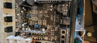
Purifi EVAL1
smps1200a400
SMSL SU-8s
Raspberry PI4
Elac FS407

My goal was to achieve the greatest possible user-friendliness, while not compromising on quality.

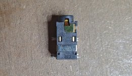
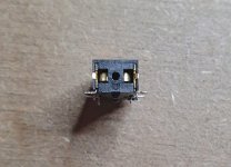
The first thing I did was buy two of these: TRU COMPONENTS 718672 3.5 mm audio jack Socket, vertical vertical Number of pins: 2 Mono Black 1 pc(s) | Conrad.com
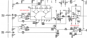
One connected to the smps1200a400 (GPIO / GND to PIN J5.1 / J5.5) and the other to the Raspberry PI (GPIO / BCM pin 21 and GND39) then just connect the PI to the smps1200a400 via a minijack cable
Notice my 5A fastblow fuse, unbelievable Ghent does not add it 🙁

index.php


My wish is that my PI should turn on my amplifier when music is playing, and turn it off when nothing is playing and after 5 minutes.

And here I must admit that I came across a difficult task. Because I can not code anything. And I could not find anything that lived up to what I want. Yes. Volumio has a plugin, it only works during play / pause and not when the music stops by itself.

So ... I had to get started 🙂

The following is code without explanation. The purpose is as written to get my amplifier to turn on when music is playing and turn off when no music is playing and after 5 min

Download, install Raspberry Lite Raspberry Pi OS – Raspberry Pi

Write an empty text file named "ssh" (no file extension) to the root of the directory of the card.

Create a text file called wpa_supplicant.conf, and place it in the root directory of the microSD card.

Code:
country=DK
ctrl_interface=DIR=/var/run/wpa_supplicant GROUP=netdev
update_config=1
network={
scan_ssid=1
ssid=“your_ssid”
psk="your_wifi_password"
}

From Mac via terminal
ssh pi@ipadress
Password:raspberry

Change the password!!!
sudo raspi-config

******************************
Update Raspiberry
******************************
sudo apt-get update
sudo apt-get upgrade
sudo reboot
******************************
Install shairport
******************************
shairport-sync/INSTALL.md at master * mikebrady/shairport-sync * GitHub

Code:
sudo apt install --no-install-recommends build-essential git xmltoman autoconf automake libtool libpopt-dev libconfig-dev libasound2-dev avahi-daemon libavahi-client-dev libssl-dev libsoxr-dev

git clone GitHub - mikebrady/shairport-sync: AirPlay audio player. Shairport Sync adds multi-room capability with Audio Synchronisation
cd shairport-sync
autoreconf -fi
./configure --sysconfdir=/etc --with-alsa --with-soxr --with-avahi --with-ssl=openssl --with-systemd
make
sudo make install

sudo systemctl enable shairport-sync
sudo systemctl start shairport-sync

******************************
Shairport settings
******************************

sudo nano /etc/shairport-sync.conf

Code:
general =
{
        name = "Eigentakt";
        volume_range_db = 80 ;
        volume_control_profile = "flat";
};
sessioncontrol =
{
        run_this_before_entering_active_state = “home/pi/pyh/stop.py";
        run_this_after_exiting_active_state = “home/pi/pyh/start.py";
        active_state_timeout = 300.0;
};
alsa =
{
        output_device = "hw:1";
};

******************************
On/off on play/pause/music stops via GPIO
******************************

sudo apt install python3-gpiozero

sudo usermod -aG gpio shairport-sync

sudo mkdir pyh

cd pyh
sudo nano start.py

Code:
#!/bin/python3
from gpiozero import LED
from signal import pause

led = LED(21)
led.on()

pause()

sudo nano stop.py

Code:
#!/bin/python3
from gpiozero import LED
from signal import pause

led = LED(21)
led.off()

pause()

sudo chmod +x pyh/start.py
sudo chmod +x pyh/stop.py

******************************
Off on boot via GPIO
******************************

sudo mkdir logs

cd pyh
sudo nano launcher.sh

Code:
#!/bin/sh
# launcher.sh
# navigate to home directory, then to this directory, then execute python script, then back home
cd /
cd home/pi/pyh
sudo python3 start.py
cd /

sudo chmod 755 launcher.sh

sudo crontab -e

Code:
@reboot sh /home/pi/pyh/launcher.sh >/home/pi/logs/cronlog 2>&1

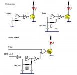
I can add if you need 3V, and not 0V to trigger your smps to turn on, then swap these start.py and stop.py so it looks like this:

Code:
run_this_before_entering_active_state = “home/pi/pyh/start.py";
run_this_after_exiting_active_state = “home/pi/pyh/stop.py";

sudo reboot
Play and forget

A "tubey" solid-state soft limiter

I propose a simple differential BJT amplifier as a soft peak limiter combined with additional asymmetric H2 distortion that is generally attributed to tube sound.
The symmetrical output drives directly the inputs of TPA3255, for instance. Setup properly, PBTL-output level is limited below the class-D typic clipping.

The LTSpice simulation shows the contribution of the emitter resistor to H2 and may intrigue you to play around with different values.
Enjoy😉

Attachments

Projects by fanatics, for fanatics
Get answers and advice for everyone wanting to learn the art of audio.
Join the Community
507,838
Members
7,890,287
Messages

Filter

Forum Statistics

Threads
406,351
Messages
7,890,287
Members
507,838
Latest member
Haihai