Melos 333 phono stage tubes placement

Hello

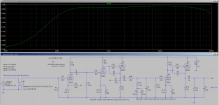
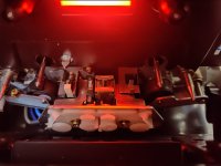
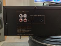
I have a Melos 333 phono stage which use 2 X 12AX7 and 2 X 6922/6DJ8.
I'm not sure where the 12AX7 and the 6922 go. As is, the 12AX7 are at the output stage and the 6922 in the front stage.
Like it is now, this phono stage doesn't have too much gain with big bass and no treble. I suspect the 12AX7 could go in the front end and the 6922 at output. I don't want to try that because I'm afraid to break something

Thanks

1dB/8va rolloff on 60V passive phono

I have been looking at doing a phono stage for quite a while now and having just "retired" I think I may get to start actually playing with it. I had been looking at passive v.s. active v.s. hybrid and was tending toward the later but I have become enamored of the idea of doing a battery powered version using either cordless tool or E-bike batteries. E-bike batteries are reasonably priced in the 36V models but horrendously expensive in the 60V models but tool batteries in 60V seem pretty affordable.

So in that vein I think that passive would be better for battery power as the supply voltage would have less effect on the response than it would using FB EQ. So I came up with this using a two stage FB amplifier front end followed by a single output stage with passive eq in between. Response follows the calculated values pretty closely but there is a 1dB per octave roll off starting at 200Hz. Being less than even a first order roll off I assume that it must be an artifact of the inverse RIAA model I picked up here rather than an actual behavior of the circuit. Can anyone confirm or destroy my reasoning here?

60vpassivephono-png.1007654

Attachments

  • 60VpassivePhono.png
    60VpassivePhono.png
    97 KB · Views: 282

coaxial for MTM center speaker with 2x SB17NRX

I'd like to build MTM center channel speaker with my existing 2x SB17NRX, cross low enough maybe around 350Hz to avoid issues with horizontal dispersion. so the option will be using 5" or 6" coaxial driver

candidates so far :
  • sb16pfc25-4-coax
  • celestion tfx0512
  • faital pro 6hx150

in my short research, it seems using pro driver coaxial have benefit to provide more headroom instead of SB coaxial. i exclude using fullrange driver (i have 1 pair of alpair 10p unused) or maybe other 5" / 6" like fostex or lii audio which has lower headroom

any input will be appreciated, because i rarely find center speaker project with coaxial, majority using midrange + tweeter combination, where low height box is also my consideration. 20cm height is the maximum that i will use because it will be placed under TV

thanks

Project 2x1 Scanspeak 26W/4558T00

Hey Guys,

i've got 2 ScanSpeak 26W 4558 and am looking for the right enclosure.

The Setup:

2x Vifa 6/1 Coax as Tops.

A Sure/Wondom DSP + Amps + the possibility to measure some room dependencies with a superlux mic (for the finish 😉

Usage is Music (all kinds of).


Now the ScanSpeak Sub seems to be made for rather small enclosures. I could give each of the drivers up to 75L. I'm more a fan of CB Systems, but this maybe a more psychological thing. I'm aware of the possibility to use the passive radiator (like troels gravesen did 😉 but i have to opt out that idea, because of the aesthetics. The Subs should look like a scaled up version of the tops. Only one chassis on the front, and a size like: height 60 width 30 depth 40 (just that you get an idea).

Can you guys help me, finding some good solutions for two enclosures in between 50-80 litres, cb or if it is much better br.. ?


Thank you guys in advance. Any informations are appreciated!


Nickelle

FS: Mullard ECC33 NOS NIB pair, EL37 1pcs

For sale is a great pair of Mullard ECC33, NOS NIB tubes. I tested them, to be sure, on my AVO CT160 tube tester. They are in great condition, as are the boxes. Everything is original. 600€ pair.

And, for sale is, unfortunatelly, only 1pcs rare Philips Miniwatt EL37, NOS NIB. It has 1282 K3 code, which indicates early Mullard production. Tested aswel, 100% NOS. 300€ 1pcs.

Regards

Attachments

  • ECC33.jpg
    ECC33.jpg
    62.1 KB · Views: 201
  • IMG_20210903_212545.jpg
    IMG_20210903_212545.jpg
    195.2 KB · Views: 177
  • IMG_20210904_114237.jpg
    IMG_20210904_114237.jpg
    57.4 KB · Views: 189
  • IMG_20210904_122648.jpg
    IMG_20210904_122648.jpg
    129.9 KB · Views: 202
  • IMG_20210904_202240.jpg
    IMG_20210904_202240.jpg
    46.7 KB · Views: 190
  • IMG_20210904_202246.jpg
    IMG_20210904_202246.jpg
    46.1 KB · Views: 136
  • IMG_20210904_202253.jpg
    IMG_20210904_202253.jpg
    75.6 KB · Views: 141
  • IMG_20210904_202326.jpg
    IMG_20210904_202326.jpg
    70.4 KB · Views: 171

CrystalFET 2 (MM) : J113 design idea

The original CrystalFET.

The original worked, and sounded nice, but suffered from a couple of issues:

1. At MC gain, the circuit ran flat out, with no degeneration (feedback) on the source of the JFET amplifiers. The circuit gain was completely dependent on carefully matching the J113 devices, and finding two with enough gain was very, very hard.

2. The circuit has negative PSRR. It literally amplifiers the B+ signal on the output. (negative PSRR!). That meant the power supply had to do all the heavy lifting to reduce ripple and noise to vanishingly small levels.

At first, my followup was just going to remove the MC gain configuration and be MM only. On further consideration, however, it seemed sensible to adopt the feedback RIAA topology often seen on the old 12AX7 tube preamp designs, to at least some ripple rejection and make the whole thing a little less dependent on having matched devices.

A recent email I got inquiring after the CrystalFET prompted me to have another look at the problem. After a bit of messing around, this is the result.

[design idea, untested, for comment]

Attachments

  • crystalFET24 response.png
    crystalFET24 response.png
    8.5 KB · Views: 331
  • crystalFET24.png
    crystalFET24.png
    17.4 KB · Views: 352
  • schem-phono-2x12ax7-nfbeq1.gif
    schem-phono-2x12ax7-nfbeq1.gif
    6.5 KB · Views: 349

Would you put these speakers in your living room?

I regularly look at TG's page and came across a new build. Something caught my eye: Those speakers have awful surrounds! 😳 And I thought if they look awful to me, what about the WAF?
We read Purifi's description:

• Low Surround Radiation Distortion
o The surround contributes to sound output. Conventional surrounds produce distortion as they
deform. PURIFI’s Neutral Surround geometry avoids this mechanism without constraining motion.
This reduces harmonic distortion as well as intermodulation distortion.


http://www.troelsgravesen.dk/Purifi-6661.htmhttp://www.troelsgravesen.dk/Purifi-6661/PTT6.5W08-01A.pdf
I suppose a grate with a nice fabric could convince a wife, although in my case I have not yet built the ones I owe her for my DTQWTII ... 😉

Attachments

  • six.jpg
    six.jpg
    151.7 KB · Views: 623

coaxial Line Array Questions/comments

Hey

All this is, is a simple quick fun speaker project that I want to do and ask a few questions about

what I want to do:

There are these silver Jaycar budget car speakers in the form of a 6x9, with there covers on they look quite industrial and
hardy, they are 4 ohms each and are 5 way coaxials and I want to buy 8 pairs, installing 8 per speaker resulting in an 8 ohm load which I want.

I dont want like some super duper high end speaker but want to turn them into a party music pumping machines, I can get 8 pairs for $320 AU here in Tasmania

I want bass only down to about 50 hz or lower and im prepared to make the enclosure 1.5 metres high and upto 50cms back and 30cm wide and it must be vented or slealed nothing else

I just want to ask what to watch out for? and any comments, because I haven't found a thing on line arrays for coaxial speakers

Replying/Quoting problems

Does anyone have problems with replying to posts and quoting them?
For most posts, if I hit "REPLY" button, the body of the message is blank.

Only in 1 in 10 cases, the previous post would be quoted in the web form.
It's been like this for a week or two...
It seems to depend on the content of the quoted post.

I'm using Firefox browser.
=================

I see now the anouncement made July 20th regarding this behavior.
While I do not agree with the idea, I understand the problem..

Power Transformer specs

I've got a hefty power transformer sitting around, taken from a 5-channel x 100w receiver built around 2002.
Pioneer I believe, long trashed.
I've ran some tests on the transformer, and posted my findings in the photo here.
What I'm asking for is.... if adapting to use this for a 2ch stereo amp, custom build, what would be a suitable A/B BJT design, and useful VA rating of this hunk of iron?

Attachments

  • Trans_specs.jpg
    Trans_specs.jpg
    28.2 KB · Views: 692

For Sale: Dayton Audio Speaker Cabinets 1.0cft MTM curved

I have three Dayton Audio MTMC-1.0BK 1.0 cu. ft. MTM Curved Speaker Cabinets Gloss Black that i am wanting to sell.

These are awesome cabinets, I have two that I used for little 8" subs and I loved them, but I got these for another project that never went forward, You know how that goes :-/

They have never even been opened and these are not for sale any longer. I'd prefer to sell in my area, I'm in seattle. But willing to negotiate if there is real interest.

I'm hoping to get 100 per box, but i'd be willing to sell all three for 250

Would cathode feedback clean up high end in SSE?

I have successfully completed construction of my Tubelab Simple SE amp. No problems so far and, in general, it sounds fantastic except for the very high end. Using the amp with either 6.5 in or 12 in very efficient Audio Nirvana full range Supers, I get significant harshness/distortion at the high end of the frequency range -- sort of like ice picks to the ears especially at higher volume levels but also there even at modest volume levels. I am running EL34s at about 23 Watts dissipation in Triode mode and the output transformers are Edcor GXSE15-8-5. Would using cathode feedback (without UL) be likely to get rid of the high frequency harshness?

Thanks

Adcom GFA-7500 Amp Module Removal

Have a customer's 7500 on the bench now. Traced the blown fuse to modules one and five and have disconnected them to test the other three, which are working fine.

The problem is that after removing the screws that hold the PCB and heat sink and the RCA jack, the module is still captured by the two 5/16 nuts that connect it to the binding post, which is in a cramped space.

Normal socket is too short to get past the shaft. Deep socket is too long to fit in there when on a ratchet.

I managed to loosen the top nut with a 12" longnose pliers, but can't get my hand into that space to loosen and later assemble that connection.

Am wondering if anyone has a better solution or suggestion for a special tool that can do the job?

Attachments

  • 20170224_110044.jpg
    20170224_110044.jpg
    439.6 KB · Views: 403

Amplifier relay issue?

Hi all,

I recently purchased a used Exposure 2010S2 integrated amplifier. Asking for your advice on something I noticed:

The amplifier makes a pop sound (through the speakers) when switching the power on.
However, it looks like there is a relay in it which clicks about 4 seconds after powering the amp on. I would suppose that is the speaker output protection relay, but
what puzzles me is that if I have a source (e.g. the cd player) already active and playing, I can hear music through the speakers
immediately after powering on the amp (no matter if the relay has "clicked" already or not yet).

I own another 2 amplifiers, an Exposure 2010 (a 2000-2001 model) and a Sony TA-FA3ES (a 1995 model).
Both of them have the relay thing which clicks about 4-5 seconds after pushing the power button on, but those would not
play any music before the relay clicks (even if the source is active already). As soon as the relay "click" is heard, only then music would be heard through the speakers.

Given the above, am I looking at a faulty 2010S2 relay or some other faulty component in it?

Frugel-Horn XL with Mark Audio Pluvia or Alpair 11 MS

Hi. I've not yet built my own speakers, but like the idea of trying it. I stumbled across Mark Audio after seeing a YouTube video about the Pearl Acoustics Sibelius speakers. They are ridiculously expensive for something with no crossover components and drivers at less than £100 a pair. If they are as good as the hype, I like the idea of building my own using the same or similar full range drivers. However, a kit would cost about £600 and the suppliers don't appear to have any demo facilities to listen before deciding if they are any better than my current Mordaunt Short MS908i Avants.

Is there anybody on here within striking distance of Cheshire that would be prepared to let me listen to anything similar that you have built? I'm thinking about either the Pluvia or Alpair 11 MS drivers in either Frugelhorn XL or the Pensil enclosures.

In the absence of any opportunity to listen, can anyone steer me in the right direction? I really like my current speakers but wonder if there is another level of performance out there in terms of retaining the base extension but improving the level of detail and precision of the soundstage?

According to the KJF website, Alpair drivers are superior to the Pluvia's and the mono suspension is a development, but the frequency response graph of the Alpair 11 MS appears to have a heavy dip half way up, well within the audible range. Is that a problem?

If it helps, my amp is a Cambridge Audio Azure and the room I listen in is about the size of a single garage.

Many thanks in advance for any help or advice.

Looking for feedback on a 3-way design

Hi,

After building a few 2-way speakers (which I'm pretty content with) I decided to try to take the leap and try to build a 3-way.
And I'm looking for some feedback on what I believe should be all right.
So after days of trying to find the right drivers that play a little nice together I came up with a system that I believe should work.
My current system will have:

  • Woofer: Dayton Audio RS225-4 (8")
  • Mid: Dayton Audio RS125-4 (4")
  • Tweeter: Dayton Audio TD20F-4

The crossover looks like this:
(Please ignore the shorted / open parts as I was still toying around with values 🙂 )
Experimental XO-schema-1.png


The FRD Like this:

Experimental SPL.png

Impedance:

Experimental Impedance.png

The only thing I'm not sure about is how to interpet phase in VituixCAD and I'm kinda hoping I've done it right 🙂

Experimental GD+Phase.png


The drivers itself will be inside a vented enclosure in which I'll make some compartements (the woofer will be in it's own compartement where the mid and tweeter will be stuck together)

So what do you guys think? Is this all right? Or did I miss something / mess something up?

Any feedback will be greatly appericiated!

Attachments

  • Experimental Directivity (hor).png
    Experimental Directivity (hor).png
    18.8 KB · Views: 125
  • Experimental Filter.png
    Experimental Filter.png
    14.4 KB · Views: 121
  • Experimental Power+DI.png
    Experimental Power+DI.png
    26.7 KB · Views: 131

Karlson's "Aural Optics"-Acoustic System patent enclosure-roughly where was it tuned?

The effects of Karlson's reflective system were mentioned in reports from its demonstation at the fall 1954 Hi Fi show K12 introduction and illustrated in the early Karlson "12" brochure as "Aural Optics". (Bose and others referenced the patent)

A "generally cubical"cabinet ("Fig.1") was used in the patent and simplified in construction with its backwave passing over a gap between its slanted baffle and cabinet top. That gap may have been 2 inches high.

Anyhow, in such a structure I think the tight end of the aperture is setting system resonance and that Karlson probably would have not tuned this cubical "K12" higher than 70Hz.

Can it be guesstimated in hornresp and assuming "so", what model would suit?


(wonder how is "sounded"? - it might be a fun bujld)

Attachments

  • Acoustic System 1955.jpg
    Acoustic System 1955.jpg
    88.7 KB · Views: 163

About capacitance measurement of electrolytic bipolar capacitors

Hi,

I am measuering a bipolar lythic of a loudspeaker in shunt position after a resistor from a bass low pass section...

On a 100uF cap I see there are few difference between the moment where the cap was pulled out of the speaker filter that was in use the day before, and then 24 hours after. The capacitance value droped from around 0,300 uF on each channel after a night rest.

After a 24h rest, the capacitance meter gives after few seconds a 0,1 uF more then few seconds later 0,1 uF more yet ! I assume it is because of the DC charging from the capacitance hand meter. However the 0,300 uF are not recovered in the few seconds when I repeat the measurement.
What is please the acurate value I should keep for the filter calculation please ?

Despite a loudspeaker filter is seing AC, impulse currents, is it safe to say the damping resistor in the filter is acting as a polarising part for few undred nano cause the bipolar cap is after ? Or it is just due to the natural loading and unloading behavior of a cap whatever it ks jn a filtef cir uit and being bipolar in seie with the signal return, i.e. negative pole ?

So what do the filter see ? The cold rested measurement of the ca pvalue or the few hundred nano Farads more of the capwhen the loudspeakers are playing back music ?

I also assume than my cheap tool is more handy for classic non polar cap measurement than bipolar caps ! But the value of the two caps with the two ways of measuring go from 103.00 to 103.3 and 103.4.... and in the filter development setup the few hundred are important enough to be heard. Ok yhe ears will find what is needed qnd I can add for instance a decoupling of what is needed with precise MKP caps, but the questions are more about knowledge curiosity.

Thanks for your testimonials. Cheers.

TPA3116D differential input conversion

Hey everyone, first of all, i'm sorry for regurgitating this topic.
I'm trying to fix the single ended input on a TPA3116D module i bought to work with my CSR8675.
I have seen other threads, posts and videos on this topic [1][2][3] but none of them were helpful here, because i don't quite understand the single-ended input conversion done on this board. (I'm a total beginner on this stuff)

So my naive approach here was to just remove C2, C3, C1, R4 and R5 and then add some bodge wires to the pads that go directly to pin 4,5,10,11 respectively on the TPA.
However, this didn't entirely work:
  • The potentiometer still has some function that i honestly don't quite understand (ideally, i'd just want the TPA to run at about 70% volume and control the gain from the CSR otherwise, because this board also has the incorrect potentiometer installed like almost every other implementation...)
  • The left output (pin 10,11) does not work at all and is just extremely noisy when i hook it up to the CSR
  • The right output works somewhat (see next point)
  • The amp seems to be in a strange state now where it won't power up "warm" (when i switch off my bench supply and switch it back on, it sometimes doesn't turn on, sometimes draws a unexpectedly high amount of current, etc., waiting a bit (presumably for caps to drain) fixes this. (I unknowingly removed some discharge resistor, didn't i? ....)
So basically i'm really confused because i've never done anything like this and could use some help from someone who has seen all these crappy single-ended input boards and can help me out. 😕

tpa1.png

tpa2.png

1: https://www.diyaudio.com/community/threads/tpa3116-csr8635-idle-noise.310628/page-2
2: Login to view embedded media 3: https://www.simplemedianetworks.com/mods/differential-tpa3116

Inspired by Linkwitz: presentation of a dipole speaker system

This will be the story of how this sketch.....

An externally hosted image should be here but it was not working when we last tested it.


.....inspired by this great piece of work (the Linkwitz Orion).....

An externally hosted image should be here but it was not working when we last tested it.


.....also inspired by some of my own experiments.....

An externally hosted image should be here but it was not working when we last tested it.


An externally hosted image should be here but it was not working when we last tested it.


... turned into this ! 🙂

An externally hosted image should be here but it was not working when we last tested it.


An externally hosted image should be here but it was not working when we last tested it.


An externally hosted image should be here but it was not working when we last tested it.

3 different cap types, all of the same rating? what replacement to use?

So I'm in the process of refurbishing that 60s made Vidaire Catalina tube amp.

Strangely, there are 3 different types of capacitors there, all carrying the same rating of 0.1uf/400v

Can anyone explain why they used different types of caps while they are all of the same ratings? Is there a specific reason for using different types?

Around each of the 6AN8 tube there is one huge yellow 0.1uf/400v cap, along with two smaller yellow 0.1uf/400v caps.

What new caps exactly should I use at each position? Is the bigger paper cap polarized? it does have a black ring on one side...

The "death cap" is also a 0.1uf/400v, also of a different type. I already removed it but wondering why they are all different?

Also... there's one 3VDC/50uf polarized cap around those 6AN8. A 3v cap on a tube? does it make sense or am I missing anything... can it just be replaced with a 47uf/16v electrolyte?

Thanks!

Attachments

  • 20211204_222728 (2).jpg
    20211204_222728 (2).jpg
    292.6 KB · Views: 213
  • 20211206_030722.jpg
    20211206_030722.jpg
    514 KB · Views: 211
  • 20211206_132430.jpg
    20211206_132430.jpg
    443.6 KB · Views: 211

Kiseki Blackheart NS

Needing more money to acoustically improve my listening room, I´m letting go of my Kiseki Blacheart NS. 11 months old, and has played exactly 30 LP´s (kept track).
I´m the only owner, and it was bought directly from the danish distributer. I only have receipt as PDF on e-mail, which can be forwarded to buyer.

Note: This cartridge is quite particular on azimut and VTA settings, so unless you are able to adjust these properly, you might want to look elsewhere.

There´s a used Blackheart for sale on AudioMarkt/Germany for 4000 Euro´s.
I´m letting mine go for 3000 Euro incl. tracked shipping in EU.
Taking PayPal (+ 4%, or the family and friends option). Preferably EU only.

Just moved into a new house, and can´t find my camera, and my cell cam won´t take close ups/macro, so photo is as good as it get´s of the actual unit.

All relevant info is available on WWW. Particularly take note of channel separation and channel balance, which are among the very best 🙂

Attachments

  • 1.jpg
    1.jpg
    157.2 KB · Views: 317
  • 2.jpg
    2.jpg
    161.3 KB · Views: 314
  • 3.jpg
    3.jpg
    166.6 KB · Views: 312
  • 4.jpg
    4.jpg
    185.5 KB · Views: 305

Headphone from Edifier K550

For a long I am using the Edifier K550 headphone just as my computer audio listening device.
I am now testing this headphone on my latest tube headphone amplifier design to
experience the amplifiers performance with low impedance headphones ranging from 30 Ohms (the K550)
(because it is the only one I have at this moment), to 70 Ohms (the Sennheiser HD25),
(the amplifier can also handle a high impedance headphone like my Sennheiser HD650).
To my very surprise with listening tests, that cheap K550 sounds unexpectedly good both at low and at high frequencies.
And yes, it is personal taste of course. So I decided to purchase another one of that K550 but to my
great disappointment I cannot purchase this type over here in the Netherlands or any other European country.
Or did I overlook something?

6.5" mids waterproofed in the doors

hi,
i'm having an issue with the 6.5 speakers, they get a lot of water on them because of poor VW door design and this actually gets a bit in the car when raining.
i've found a special sort of cloth membrane (some poliurethane from a clothing factory) which is 100% waterproof and want to wrap my 6.5 speaker in it, but this material doesn't let air go thru also.
does anyone know or have any idea how the speaker will perform? (material will not make any noise/vibrate it's very soft and has a side which is like a cloth)
i'm interested in what way will the sound be affected? will get worse? will get better mid-bass? the air behind the cone will push the cone back and obtain unwanted sound reprodution?
any idea?
thanks

Super Gainclone With Klever Klipper Based on Cordell Design

Dear All,

Please have a critique of my schematic and PCB layout for the Bob Cordell Super Gainclone "TM".

I think the C1A and C2A should go to the main ground. At present I've got it to "Quiet Ground".

Any input is most welcome.

Cheers.

Attachments

LED display problem

I use a pair of Sony CD players, model CDP-CX350. One of them has a very faint LED display. Can someone tell me if this is something that can be repaired? Sony no longer supply specific Sony parts for this model so simply trying swapping a new display panel is not possible. I was wondering if this is a common problem that can only be rectified by display panel replacement, cleaning or resoldering connections, or replacing a chip or some other component that controls the operation of the display. I don't have the knowledge of how these things work but I do have the skills required to identify and replace an IC or some rogue resistor if someone can point me in the right direction.
Thanks in advance.

odd results when calculating closed box volume for 2 drivers in series. can someone confirm

i am using 2 4ohm dynaudio 17w75xl drivers in series for a 2 way speaker.
david morison helped me before i tried using winisd. and came up with 10L for closed box volume for 17w75xl
it's a flat curve . id like a little steeper slope so tried smaller volume to boost upper bass frequencies

i am using iso-barik setting on winisd to model the output.
so when using one 4ohm 17w75xl driver in 6 L box I get the same plot
as when using two 4ohm 17w75xl drivers in 3L box. i understand 4ohm driver is more efficient than two 4 ohm paired into an 8ohm.

but shouldn't the box for 2 driver be twice the size of a box for one driver?

so shouldnt two 17w75xl connected in series require a 12L box as opposed to a 3L box

whats the error?

i attached images of winisd results
green graph is a graph of 8ohm polk mw6503 driver i am looking to replace with 2 17w75xl drivers
blue graph is one 17w75xl 4ohm in 7L box(if i put 6L volume it overlaps with 3L graph )
yellow is two 17w75xl 4ohm in series in a 3L box
Screenshot (8).png
Screenshot (9).png

Appropriate Fuse Size for Dual Amps

My car's speakers are currently powered by a four-channel amplifier. I plan to buy a 12-inch subwoofer as well as an amplifier to power it. I've run a 4 gauge wire to the trunk for my existing amp. I'll get a distribution block and connect it using 4 gauge wire, as well as 8 gauge wire from the block to each amp. My question is: how do I determine the fuse size to use? I already have a 60amp fuse for the current amp, and I'm not sure what size fuse I'll need to replace it with. Do I replace my 60 amp fuse with a 120 amp fuse or leave my 60 amp fuse because the new amp will almost certainly require a 60 amp fuse? I believe I only require a single 60 amp fuse, but I'd like to double-check before purchasing anything. Thanks.

6N17B Phono

I just stumbled across the 6N17B pencil tube and it looks intriguing as a phono preamp input tube as it has fairly high mu and reasonable input capacitance. I suspect that it might also be fairly free of microphonics.

I suppose that these types of tubes might be inconvenient having no base but I suppose perf board could be used. Pencils could be a very interesting subspecies to play with.

Weird Drivers Catalogue

I've been doing some driver 'research' in google images and came across a couple of unusual drivers I never expected to see.

I thought it would make a fun thread to collect images and details of unusual or weird drivers.

I'll start with ScanSpeak coaxial that appears to have polystyrene slapped on the front!

https://s3t.it/weirdness/scanspeak-13m-coaxial/
s13m_coax_01.jpg

s13m_coax_03.jpg


Next we have a grotesque version o the famous ScanSpeak mid-bass.

https://diyspeakers.eu/product/scan-speak-11m-4631g05-gold/
Scan-Speak_Gold_11M-4631g05_midrange.jpg

Scan-Speak_Gold_11M-4631g05_midrange_side_view2.jpg


Then I'll add this one because it is such an unusual suspension arrangement, at least it is these days.

IMG_20150710_153019.jpg

IMG_20150710_153028.jpg

DAC block chain and the big picture in DIY DACs?

I, like many of you, would like to build my own DACs because I like to build and explore, and also because I am tired of trying to fix the stuff I have and keep up with new USB protocols - I'd like to have the ability to do my own hardware updates.

If I understand correctly, DAC's are generally set up like this:
Digital input interface -> DAC conversion stage -> Analog pre/voltage stage

(And of course a well designed power supply for the whole rig)

Is this correct?

Are there resources out there for me to purchase USB interfaces but build my own I/v, analog, and PSU's? The only resource I'm aware of are the Audio Note kits but there must be more, right?

[Edited and changed I/V to DAC as per iggy's comment below]

power supply for baldwin reverb box

Hello, my name is omar, i built a tube amp and now i want to add a reverb unit i found. how can i power this clean and hum free? it is going to go into a clone of a bassman 5f6a it is originally from a baldwin organ. I think the transistors are S429-2? cant really find much..but i need the 22+ I would be able to build a ps with its own transformer? HELLP i dont want to screw this up.

4367175876_f2f231f5f4_o.jpg


that schem is one half of it....it has two springs/circuits....here are pictures of the unit:

4370210973_21da5b4652_o.jpg


4370210907_34e2d127a8_o.jpg


I really dont know how to find out about what kind of power supply to build...i dont know how much current should it get? i dont know anything about time variant equations either...well not enough to find out the total power i should give it.....if someone could help me with a ps circuit i could trade for more schematics (knight, bogen, setchell carlson, redd47,) i even have a wurlitzer reverb tank that needs power maybe for sale or trade as well...so whatdoya say?

Step down 12v to 9v

Hey everyone!
So here’s the scenario I’m trying to simplify. I have multiple audio/video interfaces and all of them run off 12VDC except one that is 9VDC. The space available is small, so versus having to eat up room with an extra wallwart I would love to run a single larger current 12v supply and use either a small step-down buck converter, LDO, or any other suggestions to supply 9v to the single audio interface. The stock 9v power supply is 2A.

Any suggestions? 🙂

SCOTT PS 48A 1 Turntable, any good?

Hi All.

Just been given a SCOTT PS 48A 1 direct drive Turntable.
Are these any good?

It ha a cartridge which I haven't been able to identify.
Marked SSM / 5, with 2 circles and 3 parallel lines above the letters.
Any information would be appreciated.

Thanks Cliff

Attachments

  • SCOTT PS 48A 1.jpg
    SCOTT PS 48A 1.jpg
    254.8 KB · Views: 455
  • SCOTT PS 48A 2.jpg
    SCOTT PS 48A 2.jpg
    126.6 KB · Views: 362
  • SCOTT PS 48A 3.jpg
    SCOTT PS 48A 3.jpg
    234.7 KB · Views: 357
  • SCOTT PS 48A 4.jpg
    SCOTT PS 48A 4.jpg
    236.7 KB · Views: 340
  • SCOTT PS 48A 5.jpg
    SCOTT PS 48A 5.jpg
    301.7 KB · Views: 395

Counterpoint DA11.5 circuit needed

Good day,

I am having problem with the counterpoint DA11.5 cdp which always shows "error" when reading the CDs. During reading, the CD will spin for a while, stop and then "error" popup after ~10seconds later. I tried with new optical pickup (VAM1202 as I am not able to get VAM1201 over here) but "error" remains there.

Does anyone has the schematic for this DA11.5? I know I can get from the counterpoint's site but it is just too $$$ for me. 🙁

Regards,
Liew

Ideal speaker shape to make at home

I've read some threads about getting rid of resonance and standing waves

It seems ideal shape would be a sphere with a transmission line

If you are making a rectangular box and have limited machining/carpentry tools, what would be the best thing to do to help with resonance?

Would making side walls in triangle shape help?

Basically imitation of some b&w speakers where left and right wall of the speaker cabinet converge..so a horizontal cross section would look like a triangle more or less.

McIntosh MC430 information thread

There doesn’t seem to be any info on this amplifier out on the web, so I’m posting it here for future reference.

This was the first McIntosh car amplifier made, all the ones that came after looked very different. It’s 4x100 watts, .005% THD. Idle current is around 3.5A at 13.8VDC, and it has a rather odd plug for remote turn on. There are actually 4 pins- one is remote not sure what the others are for, but possibly power guard signaling as in the later units.

The plug itself is a pull to release Hirose connector, I was able to figure out the part number in case anyone wants to order one. I just got a pair myself off eBay for around $20, the part number is HR10A-7P-4P.

Attachments

  • 6F5F8ABE-14B7-4A82-A4EC-58A90EEEB88D.jpeg
    6F5F8ABE-14B7-4A82-A4EC-58A90EEEB88D.jpeg
    239.5 KB · Views: 141
  • Like
Reactions: chrchp

How to adjust Peak Level Detector

Hello,

This is my first question although I have been browsing this forum for a long time.

I'm working on a design of a Peak Level Detector in combination with a VU Meter. The VU meter works great, It is proven to be working as intended. The 0dBu is set at 0,775Vrms with a 1kHz sine.
As 'peak' level +3dBu is set with this 1kHz sinus testsignal. When adjusting the Peak Level Detector to +3dBu, the LED turns on. At 0dBu the LED turns off. So it seems the design is working.

When using with music however, I noticed that the LED turns on much earlier than +3dBu. The LED starts to turn on at around -6dBu. The VU meters are working as intended. When checking with a recorded testsignal (1Khz/sinus), and parts of music on the same tape, the VU meter and the Peak work as intended at the part of the testsignal. When music is played the problem is again visible. It seems that with a complex (music)signal the Peak Level Detector turns on to early. Tests have been conducted with a 1Khz square, sawtooth and a triangle. And results ar roughly the same. LED turns on at +3dBu. It depends a little on the type of music is played but in general only with music the LED turns on to early.

I wonder has this to do with the Crest factor? What kind of signal and/or level of testsignal will adjust the Peak detector at the desired +3dBu correctly?

Regards,

Nev

FS/SWAP Scanspeak d2905/9700 R2904, Aurum Cantus G2SE tweeters

Hi,

Never really posted anything here, but site has been great inspiration for me.

I have around too many drivers lying around from past 10 years of my DIY journey some never even used, so decided to do a bit of a clearout and sell a few drivers.

Got 3 of Scanspeak D2905/970000 tweeters. Only ever used for about 50 hrs in one of my first projects, but could not set them sounding right. Originally bought for front three in home cinema. Will sell at £60 each + postage. Would ideally sell all three together, but might split.

Pair of Scanspeak R2904/70000 - this is brand new never used boxed pair. Bought but never used due to change of plans. This is the pair with silver fronts. Want £275 for a pair plus postage.

Also have brand new pair of Aurum Cantus G2Se ribbon tweeters. This is factory special edition of G2 tweeter which is not available in retail stores and is only sold to manufacturers. Want £175 + postage for this.

All items are available for collection from Manchester. Or can deliver pretty much everywhere in world if you pay postage. Bank transfer prefered, but paypal is possible but cost to be covered by the buyer.

Will also advertise few other cheaper drivers once I get everything sorted and tidied up.

Thanks

Ported TB W3-2141 - port sizing and freq response

Hi there!

I 3d printed a port computed with WinISD. Box is 2.83L of internal volume and tuned to 76.44. Port is 32mm x 12mm. I followed suggestions about making a port with the biggest area you can afford in the enclosure leaving a port diameter clearance. I really like the way it sounds, if I compare with the PS95 after getting the recommended passive elements to tame the peaks.

Questions:

  • Do you like this rule and if so, does it apply to small speakers? With 5W I get port wind speed = 14.
  • Is it better to model to the max wattage you are planning to use and have speed close to 20?
  • Is the frequency response acceptable? Can I do better with a speaker this size?

Thanks.

1640061560027.png
1640062276469.png

Looking for a design/existing-project for small high-quality sub

Hi,

I'm looking at extending the bottom range of my system a bit with a sub. This is in a small room (12 square meters ~4m x 3m).

I have 2way speakers I built with Accuton C173 drivers and Mundorf AMT tweeters. 17l vented enclosure. They sound wonderful but sometimes, I little more "oomph" at the low end would be nice.

Amp is tube based 35W. Loud enough for this room.

I figure an active sub is called for that would feed off the speaker connection from the amp (hi-level connection). That needs to happen in a way that doesn't do wired things to the impedance that the amp sees. The speakers have a very well designed impedance lineraziation which works well with the tube amp and I don't want to mess that up. I don't know much about active sub-woofer designs but in theory, it shouldn't be a problem I think as that input would have super high impedance that is totally getting dominated by the impedance of the speakers. But then again, I have not done this before so I'd rather use a prooven design if possible.
Obviously, bringing a solid-state active subwoofer into a tube setup might feel like a bit (or a lot) of blasphemy to some but I think it's a good option in my case. I don't have space in this room for huge full-range speakers so I'm good with mixing whatever gets the job done as long as the quality is right.

Given that the system is of quite high quality, I want the sub to match that and use high a high quality driver and electronics. Using ready-made modules would be OK but I'd rather build the electronics myself so I have some say in parts selection.

With the limited expirience I have, just looking around, I think I'd build a closed box (60l) for a 15" Timphany STW. I think a vented design would be too huge given that this is a small room. I don't need a lot of volume. I'ts just about extending the range of the system into the lower regions while maintaing tightness and definition of the sound.

Rather then figuring this all out on my own (which is fun but also error-prone), if someone knows about an exiting project which has proven itself in practice, I'd rather start with that than building from scratch.

General question about high-level inputs/outputs and crossovers in active subs. Would this be design in such a way that it represents a high-pass to the signal that is going to the main speakers or would it just represent a voltag divider and sit in parallel with the main speakers and then use a low-pass internally when feeding its own output stage that's hooked up to the driver?

Thanks,
Lars

Woofer moving in and out before sleeping

Hello DIY,

My active speakers/ monitors ( Event Opal) , 2 way, with AB amps, started doing something interesting recently.

When powering off, the woofer, on one side/ channel only, moves in then out. Sometimes accompanied by a slight thump.

The other side/ channel, doesn't move much if at all, and is quiet.

This is a new characteristic

What could be going on?

🤔

FS: Alesis Masterlink ML-9600

As I continue cleaning the audiophile closet, I find that I have an as-new Alesis Masterlink ML-9600 that I would like to sell to someone who has a use for such a device. Currently packed in original double box with all accessories. I don't believe that this was used more than a few weeks, then packed away. Here's a review in Stereophile by Michael Fremer. Product Overview Sheet here.

I see these are currently going for $249 to $299 on eBay. I'm fine with $150 if a diyAudio member is interested. PM me for more info.

Attachments

  • IMG_4259b.JPG
    IMG_4259b.JPG
    409.4 KB · Views: 131
  • IMG_4260b.JPG
    IMG_4260b.JPG
    313.7 KB · Views: 109
  • IMG_4261b.JPG
    IMG_4261b.JPG
    350.1 KB · Views: 116
  • IMG_4262b.JPG
    IMG_4262b.JPG
    301.6 KB · Views: 102
  • IMG_4263b.JPG
    IMG_4263b.JPG
    532.6 KB · Views: 136
  • IMG_4268b.JPG
    IMG_4268b.JPG
    409.5 KB · Views: 138

Nakamichi DR-2 Ground Loop Problem Fix

I don't know if this problem is common across all Nakamichi DR series cassette decks or just in the DR-2 model but here is what I found in one and how I fixed it.
When measuring various aspects of the deck I noticed this harmonic noise comb in the source monitor loop. Not evident in the tape monitor loop. Either because absent, line muted, or tape noise covered.
After examining it I understood the ground-loop's root issue and decided a least intrusive solution. To simply insulate the RCA quad's grounded face plate from the chassis.
I punched a white Post-it paper with a BIC ballpoint using the back of the chassis as template for the RCAs to feed through. It worked... Here are the FFT results.

I believe this fix will prove useful to Nakamichi DR owners. It increases the bass to mid resolution (less grunge noise) in the source loop during the recording process.

Attachments

  • Nak DR-2 REC.jpg
    Nak DR-2 REC.jpg
    371.6 KB · Views: 433
  • Nak DR-2 Heads.jpg
    Nak DR-2 Heads.jpg
    430.9 KB · Views: 286
  • Nak DR-2 Under The Hood.jpg
    Nak DR-2 Under The Hood.jpg
    1,008.7 KB · Views: 412
  • Nak DR-2 Source Monitor Fix A.jpg
    Nak DR-2 Source Monitor Fix A.jpg
    530.7 KB · Views: 285
  • Nak DR-2 Source Groundloop Fix B.jpg
    Nak DR-2 Source Groundloop Fix B.jpg
    815.2 KB · Views: 316
  • Nak DR-2 Source Monitor Fix C.jpg
    Nak DR-2 Source Monitor Fix C.jpg
    323.4 KB · Views: 257
  • Nak DR-2 Source Monitor GND Problem.png
    Nak DR-2 Source Monitor GND Problem.png
    31.8 KB · Views: 258
  • Nak DR-2 Source Monitor GND Fixed.png
    Nak DR-2 Source Monitor GND Fixed.png
    34.3 KB · Views: 302

Ceramic Resistor Max Temps?

Anyone know what the maximum recomended operating tempurature of a 5 watt sand/cement/ceramic what ever you call the little white coffin type resistors is??

I am working on another SWR bass amp that failed because the resistors got so hot they melted the solder!!!

These amps use two 5 watt 1100 ohm resistors piggybacked and two 7.5 volt zeners in series to drop the +/- 75V down to +/-15v

I measured over 200 deg F / 100 Deg C right on the resistor body! that seems a little too hot for me!

I also noticed that the flux around the resistor legs where they are soldered together was bubbling!

This really seems like a serious design error if these resistors are running that hot. thats 2 amps now that have failed for the same reason. this one only partially failed. It was exhibiting odd performance fluctuations. sometimes it would run fine, others, it had no power and ran very hot. I found that when one of the resistors would lose contact, the amp would oscillate at full power! NASTY! Luckily we caught the problem before the amp went POOOF!

I have to find a cost effective solution for these things. there just isnt any room in there to mount 10 watt resistors.


Im still working on the pass regulator boards, havent had any time to test them yet however.

Zc

How to bypass stepped attenuator Allo Volt +D

Hello,
I have an Allo volt +D that I want to put in a smaller box and, as I don't use the volume control and it is quite bulky, I want to get rid of it, and ideally substitute it for a two position switch (max. Vol and say 60% vol).
Does anyone know which of the 6 cables I need to short or connect resistors to (in the case of the switch option)?
Thanks a lot in advance.

Robert Fosgate Power Rails

I have a Rockford Fosgate R1200-1D. When I enable the amp the power rails power up. +- 50vdc. However the rail voltages doesn't seem to be making to the power transistors. I assume the +/- 50 volts should be showing up on the power transistors also. And oh yea, the blue light is on. Is there a couple of switching transistors that switch the power rails to the power transistors? Does anybody have schematics for this amp, or can tell me where I may be loosing the power lease?

Al
Report Post

"Upgrading" SEAS Idunn to Bragi

Quite a few years ago I built three SEAS Idunns using kits and pre-finished cabinets from Madisound. Originally they were uses as LRC in my apartment's home theater setup. Now that I'm in a house, I use two of them in my PC soundsystem while continuing to use one of them as a center channel.

I'm in the process of building some DIYSG Volt coaxials for surrounds and a center channel, which will leave me with a spare Idunn that I can use to experiment with.

My experience with the Idunns has been that I like the sound of the drivers, but the overall tonal balance is a bit bright (especially sitting close to them) and the bass has always been anemic. I never loved them on their own running full range. In my current setup, I have them crossed at 100Hz to a very powerful array of eight 12" sealed subs. I have a high shelf to tame the treble by a few dB. This setup sounds amazing, but the Idunns start to run out of steam a bit earlier than I'd like. They also lack punchiness in the midbass. I'm also just ready to try something a bit different.

The design goal of this system is to be hi-fi for daily listening but with the ability to crank up the bass and get loud when I practice DJing. Trying to have it both ways. The room is small at 11'x11' but treated with some bass traps and absorption panels.

One option is starting over and building entirely new and different speakers from a kit or from scratch. Put that aside. The other option is buying an additional SEAS woofer and going MTM.

My skill level: I've got a measurement mic and Dayton Audio DSP but have only done basic in-room response measurements of my finished system for EQ purposes. I've never done cabinet building or crossover design. I may be willing to dabble in both for this project, but wouldn't mind keeping it simple.

Which leads me to my questions about the SEAS Bragi design.

1. These woofers say they are designed for ported enclosures, but given my subwoofers I have no need for bass extension. Would they perform well as MTMs in a sealed 24L box if I were to reuse the Idunn cabinets with a new baffle (the Idunns being front-ported)? Would the crossover need to be redesigned for this?

2. Assuming I built new 30L cabinets for the Bragi, should I use the SEAS crossover design given my opinions on the Idunn voicing? Are there any issues with the crossover in general that jump out at the experienced designer? I figure if the crossover point and overall topology are good, I can probably tune the tonal balance to taste with my DSP rather than messing around with padding the tweeter or whatever, but if there are bigger issues then perhaps I'd take a stab at a different crossover or run them active (I'd need to purchase an additional amp, but that's ok). Keep in mind that my listening distance is about 5 feet, so driver integration is very important.

Thanks in advance.

Eclipse DA7232

I've got a little work cut out for me here. I'm thinking either this amp suffered from reverse polarity, over voltage, or possible just the Pre-amp FET (BUZ11) overheated. Its got a small sync on it. This FET burned the board pretty good but seems the large traces can be easily reconstructed after cut-out. I'm planning on mounting the new single FET to the main heatsync afterward.

SO, I realize theres not much literature out there on these amps so here goes. The amp is using 4 powers supplies, but the power supplies won't start until the one BUZ11 on the Pre-amp board starts. After which, the main PSs supply the two B&O Icepower A1000 modules.

In previously servicing another one of these; I know the amp should power up with the IcePower modules removed. See reference thread a few months ago: Eclipse DA7232 - ICEpower 1000A?

I dont have that other amp any more.

The failed BUZ11 caused some trace lifting on the Pre-amp board, trace also burned up. Also a trace on the main PS board got hot enough to burn the topcoat but seems to be OK.

LM2574M +5.0 P+ is driving the BUZ11 FET. After figuring out the ground trace was required I can observe clean drive signal to the gate of BUZ11.


I'm at the point where I need to cut and then build-up, but I was wondering what D201 is? Its missing and I dont know what it should be. Anode source and Cathode to drain. Is this just a reverse polarity diode? 1n4004? Or perhaps HER105?

The other missing resistor is a 2w 1ohm which happened to be in a parts bag inside the amp.

Photos coming

Orion 425HCCA Gen 1 has some DC offset

One of the amps in this model was damaged; I repaired the PS bjts 2n6488, and ALL caps in this amp. Now one channel has 2.5vDC on it, and the other has -0.6vDC on it. With a speaker load, the amp draws just a few amps of current as it sucks in the speaker just slightly. The channel with 2.5vDC on it has a lot of noise through a test speaker. I replaced the 5532 opamp, and pulled the 5533 opamp to clean under it's pads. I dont have a replacement for the 5533, except I may try swapping the 5533 from the good half of this amp which is actually working just fine.

Good rail, +-18vDC. Good regulated +-14.5vDC.

Nothing seems open, shorted, or anything. Any clues where there might be so much DC on those channels?

The other amp's half, which I also replaced ALL electrolytic caps is working just fine.
Projects by fanatics, for fanatics
Get answers and advice for everyone wanting to learn the art of audio.
Join the Community
507,797
Members
7,888,839
Messages

Filter

Forum Statistics

Threads
406,261
Messages
7,888,839
Members
507,797
Latest member
Moza