For Sale Inexpensive Tube Power Amp HV Supply Transformer Set - $50

I had Heyboer wind a couple of pairs of power transformers for the Eico HF-87 / 89. The first pair was spec'd when our mains was 125V -- it has since dropped 5V.

The original transformer was designed to deliver about 187 VAC on the HV side (which when doubled & rectified gives > 450V); 75V for fixed bias, and 6.3V @ 7.6A !

These units have been tested under 120V and all output voltages are low. That can be fixed with a boost transformer that I'm including with Hyboer's Eico iron. Adding the included boost transformers gets the voltage closer to spec (may vary a bit with your line voltage).

Get the power transformer and the boost transformer for only $50 (+ shipping).

(I've attached a schematic of how to hook it up)

Attachments

  • Eico 30031 Boost.png
    Eico 30031 Boost.png
    9.2 KB · Views: 144

Soft dome tweeter that works in a 129 dB SPL capable speaker?

The soft dome tweeter capable of maximum SPL I can find is the ScanSpeak Ellipticor D3404/5520-00 38mm Elliptical Dome.

Are there other players in this ballpark?

This is for large format studio monitors.

This Dynaudio Monitor claims a peak SPL of 135 dB per pair, which should be about 129 dB per speaker...

Does anyone know of a soft dome tweeter which can match up to this?

Which Class of Amplifier would this Schematic fit in?

Hi
Just to make it clear, this Circuit consist alot of a schematic drawn by or designed by Rod Elliot, and also some Parts where Nelson Pass plays a Big role in it, when he helped me out to correct my thinking of many different calculations, with the test Program I use.,
His major speech to me was something like that..
"I'm interested in the real world Amplifier more than simulations" and of course he is right, he's Nelson Pass, the Master of Amplifiers.

Also he showed me the shortcomings, of the last build of mine.. In fact it isn't a shortcoming for me because I designed the Amplifier as it is today, and it turned out better than I expected. The Single End Class A Amplifier from one of my last threads. But there is no playground if it comes to professional Designers and Builders as Nelson Pass and Rod Elliot are. the all has to be by the book. I dreamed of 25 Watts, I got over 30@8 Ohm with THD of less than .5% and less than .05% @1 Watt RMS in my last build..

Of which I have to say that this one just works like a dream and Charm and it sounds real good. Natural...

Mr. Nelson Pass was it, who wrote to me, that using RE a 250 Watts Resistor would lose too much power compared to Power Consumption, and this is TRUE (this in my last build) and that it would be better to stick with Constant Current Source for the Class A. But the levels I listen too are in the range up to max 5 Watts, anything else is just too loud.

But Constant Current Source Class A Amps, I had already done 2013 / 2017 which has again grown out of a design from Rod Elliot DoZ circuit, but which was completely modified by myself. I had sent the modifications to Rod Eliot by email that time, so he knows about this. And this here is the EXTENSION 2021 with some modification compared to that 2 Constant Current Source Class A Amps, I build in 2013 and 2017 respectively, both which are in best condition till today..

Now the circuit you see I added is a Mix of all these Inputs I've got from Nelson Pass as well as from Rod Elliot's designs and from other sources, many thoughts, I read here, I try to implement here.
I call it Variable Current Class A Amplifier, even I know that there is no VARIABLE CURRENT if it's Class A.

In fact, Adding one more resistor and adding a simple three pole switch can turn this amplifier into a CONSTANT CURRENT SOURCE CLASS A in no time and it can be freely adjusted beginning at 200Milli-amps up to 20 Ampere Idle

The reason to do this (Variable Current Source) is, I try to handle the current when there is no signal on the OUTPUT Transistors, that it will be around 500 / 750 Milli-amp while IDLE but will get full Current on Full Load. So may I can help the ICE BEARS, that the White Gold for them *ICE in the Arktis* will stay somewhat longer..

But I'm not really sure if this still fits into Class A.. that's why here again my Question,

What Class Would YOU put this AMPLIFIER into.??
BTW this amp is working on my Bench as you can see it in the Schematic, here.. it has a few add-ons to compensate heat and to keep Super 0.0000Volts at the output at anytime while running.

Right now I'm drawing the Artwork, or call it layout for large Heat Sinks, 400mm X 150mm X 100mm.

The Design *Simulations* showing 3 versions you can have the read out in that yellow window, once with no SIGNAL at the input but Amp is running idle, and once with 1Khz under Full Load driven into 4 Ohms and then also driven into 8 Ohms and also with Signal switched off.

This way class a could be suitable while in IDLE State, using a mere of 18 Watts while in Idle *depends how high Bias is set too*, about 30 Watts up to 10 watts output and 180 Watt for full output Power. Can this still be considered as CLASS A? More follow soon.

Thanks for any Input.
Regards Chris Hess

Attachments

  • 1. Class A - No signal 8 Ohm.jpg
    1. Class A - No signal 8 Ohm.jpg
    178.1 KB · Views: 703
  • 2. Class A - Full Load 8 Ohm.jpg
    2. Class A - Full Load 8 Ohm.jpg
    177.7 KB · Views: 692
  • 3. Class A - No Signal 8 Ohms.jpg
    3. Class A - No Signal 8 Ohms.jpg
    189 KB · Views: 644
  • 3. Class A  - Full load 8Ohm.jpg
    3. Class A - Full load 8Ohm.jpg
    205.2 KB · Views: 607
  • 5. Class A - Idla No Signal 4 Ohms.jpg
    5. Class A - Idla No Signal 4 Ohms.jpg
    200.5 KB · Views: 599
  • 4. Class A -  Full Load 4 Ohms.jpg
    4. Class A - Full Load 4 Ohms.jpg
    205.5 KB · Views: 223

Digital stream source with dsp?

Been out of ther game for a while so not sure where to start.
im looking for a streaming option that will let me play spotify and also accept a digital input from my tv. Also need to go to a active 2 way dsp with mono subwoofer out for some active 2.1 monitors.
I know in the past mini dsp offered a solution but I dont know what is currently available. Maybe the Arylic up2stream pro then onto a dsp solution?
Also not opposed to a dsp based amplifier, around 0w x 4 will be fine

Cheers, Beau.

Orion 222SX Gen 2

THis amp needed ALL aluminum caps replaced. Some board corrosion caused by the 470uF caps in the audio section. I also replaced all 5x NE5532 opamps as they were quite corroded as well and there was bad DC on many of the legs and speaker terminals. I now have some decent audio at speaker terminals, but only with the muting jfets removed. When the jfets were in circuit I could get some audio, but the lower waveform was clipping on one channel badly, and the other channel had barely any audio. With them removed, audio is cracking very badly. I replaced the gain control and also cleaned and checked the Mono and EQ buttons for operation.

Whats most likely to cause crackling at terminals? I see fluctuating signal even on RCA center with my scope.

Second, why is the amp half in mute?

help me figure out this noise

help me figure out this noise (solved)

hi all. I'm afraid I do not possess all the necessary knowledge to wrap my head around this, so maybe someone could point me in the right direction?

A pair of old Genelec 1030a, they were issue-free until a couple of months ago, when gradually, one then in two weeks the other, both began exhibiting a loud hiss and a bit of buzz when first switched on, or simply when the room is colder.

I know my way around audio, so I've ruled out noisy source, interference, ground loops, bad cables, etc. I checked the PCBs for visibly faulty components but could not find any. I suspected the filter capacitors on the power supply at first, so I replaced them, but that made no difference.

In each speaker, the amplifiers are mounted on a large metallic backplate which acts as a heatsink for a pair of STK404-100. When the plate is cold, the speaker box produces a lot of self noise. If I blow on the plate from the back with a hairdryer and get it a few degrees warmer, the noise goes away. When cold, the noise is in both the woofer and tweeter paths. I tried getting individual components on the board hot or cold but nothing makes any difference until I warm or cool the metal plate itself (which in turn warms or cools the STK ICs, they prop the PCB up from the plate). Taking care not to warm the PCB itself, just the plate, still makes the noise go away.

Both speakers have the same issue.

I'm super puzzled. That room temperature of 18-19C or so can be too cold for these amps to sit stable - what a bewildering idea. Like all things Genelec, schematics are hard to find (1030a and 1031a are quite different). edit: I understand class AB amps (like the 404) have thermal "specifics", that's where I stop comprehending.

I'd be very grateful if someone had the expertise and patience to explain what this might be? STK 404-100 datasheet is here, and here's a photo of the treble part of the board. Any help or ideas much appreciated!

Need advice on dealing with a Fountek NeoCD3.0 tweeter

I working on designing a surround speaker using the Fountek NeoCD3.0 ribbon. It has a 7db hump from 10khz to 20khz and I'm not sure if I need to deal with it. I have been testing it with a DSP to help design a passive crossover. I have listened to it with a high self filter to flatten it out and I can't hear much difference, maybe the high end loses some sparkle, but honestly it doesn't sound bad without the high shelf. Now I admit I'm old and can't hear past 12-14khz so that is why I'm asking. Simulating the crossover in VituisCad a 100mh inductor in line with tweeter will get rid of the hump and because it is a low pass will not be self filter but a 6db per octave filter. Here is link to the specs for the tweeter and the hump clearly shows on axis in the plots. I have also attach my on access measurement

https://www.madisoundspeakerstore.c...3.0m-blk-3-ribbon-tweeter-round-flange-black/

Attachments

  • NeoCD30.jpg
    NeoCD30.jpg
    127 KB · Views: 285

  • Poll Poll
Dayton 18-22 vs sundown ZV4 18d2 vs ...?

Which option to choose?

  • UM 18-22 ported

    Votes: 2 16.7%
  • UM 18-22 sealed

    Votes: 1 8.3%
  • dual UM 15-22 ported, seperated

    Votes: 1 8.3%
  • Dual UM 15-22 ported, in 1 box

    Votes: 1 8.3%
  • dual UM 15-22 sealed, seperated

    Votes: 2 16.7%
  • dual UM 15-22 sealed, in 1 box

    Votes: 1 8.3%
  • ZV4 18 ported

    Votes: 0 0.0%
  • ZV4 18 sealed

    Votes: 1 8.3%
  • other

    Votes: 3 25.0%

Hi,

First off, I'm from Europe, so US drivers are slightly more expensive here. I've had some experience building lilmike horn subwoofers, liked them, got divorced, moved twice, and sold them because moving them was too heavy😀 I like to do woodwork, have all the tools you might need...😀:clown:

Now I settled down, and I'm looking to extend my current system. Main use is for HT, also some music. Main speakers are currently Canton CT2000 speakers. Not sure if I will keep them, would like to move to bigger infinity speakers as I like my Qb's as well, but my girlfriend likes the look of them. (other topic on that...)

My living room is actually 'Z' shaped, my TV is in a part which is 5*4,5 M. this gives out to a space of about 5*11 m and there is a veranda of 6*3M. So I do need something with an 'oompf' to notice something. There is a concrete floor with a solid wooden floor on top.

Budget: I would like to spend about 500 EUR for the driver(s). I have an amplifier, QSC EX1600, can do 1600 4 ohm in bridged. Also the mini DSP I have from the lilmike project. So should be enough power.

Space: I can build a box with an internal volume of about 250L (about 8 ft3). this is just big enough for a coffee table and by coincidence the recommended size for a ported UM 18-22😀. I agreed with the GF to add a concrete top on it:clown: Will add some mass to the sub so a win-win😀

Drivers: I have found multiple options available at a reasonable price:
- Dayton UM 18-22 d2, 410 EUR
- Sundown ZV4 18d2 (2nd hand) about 500 EUR
- 2 Dayton UM 15-22 d2, 580 EUR

Enclosure:
ported seems to be better given my room size and the limit of having only 1 sub. I have a preference towards a downfiring sub for the looks. If going for 2 drivers however, I do not have enough space to put them both downfiring, I would make 1 down and 1 front firing. Don't know (yet) where I would put the ports in that position. Best to make a sub with 2 drivers in 1 enclosure, or better put a divider in the box?

According to the guy selling the sundown, it beats the other 2 options as more db are generated on low frequencies. What is your view on this? The Fs of the Dayton is way superior in my opinion, but the xmax is more important according to the seller, it moves more air.

Other options I should consider?

thanks in advance for your help!

Room advice - minimal dimensions

I am in the planning stages of a listening room added to a garage area. The garage interior is finished with wallboard, and the current ceiling height is 11.5 feet (3.5 m). Based on my current speaker/listener positions (currently in an open floorplan room, living/dining/kitchen), which forms an equilateral triangle , I am thinking that I could have minimal room dimensions of 9 feet (2.7 m) width and 10 feet (3 m) length. I am assuming that with enough sound damping and diffusion, I can correct for the minimal distance in this room from the speakers to the side and front walls, and listening position from the back wall. I have always liked the sound of rooms with high ceilings (such as lofts) relative to width and length. I have no issues with claustrophobia. Greatly appreciate any advice.

The Phono Stage, single child

Hi

Years ago a friend of mine ask me for a tube phono preamp.
So after some months of tests and designing the box and pcs, serviec ,etc. the final stuff was ready
In the first photo the front panel.
In the second photo the internal seen form above. In the left the phono pcb + Ht stabilized.
On yhe right the power section with three toroids, 100m w each, two for HT and one only for filaments and services; the first step on HT was done iwth GZ34, one for each channel.
In the beginning the HT was C-L-C-L-C with a very low ripple then I move to ss HT to get a better results also under listen tests.
The entire circuit is full dual mono
There is a little pcb fixed on pin jack where is possible to select two inputs and chancge 6 different load.
In attach also the circuit; it use EF184 in triode mode for gain, all Telefunken nos/nib, and 6922 for CF
There is also the possibility to have three different gain selected from panel, 40, 43, 46 dB
The max input overload at 1 kHz is 280 mV to get 1% of THD in input with 33 Vrms in output
At 20Hz the overload is 25 mV and at 20 kHz is 800 mV
In attach the frequency response and FFT at 2 Vout plus THD vs frequency at 5 and 10 Vout


Walter

Attachments

  • Phono_Stage_Apertura.JPG
    Phono_Stage_Apertura.JPG
    106.6 KB · Views: 306
  • Figura 6_Phono stage_interno_1.JPG
    Figura 6_Phono stage_interno_1.JPG
    224.6 KB · Views: 303
  • Figura 7_Phono stage_laterale.JPG
    Figura 7_Phono stage_laterale.JPG
    135.8 KB · Views: 306
  • Figura 9_Phono Stage_ingresso_pcb.JPG
    Figura 9_Phono Stage_ingresso_pcb.JPG
    239.4 KB · Views: 410
  • Figura 4_Schema Phono.jpg
    Figura 4_Schema Phono.jpg
    61.1 KB · Views: 398
  • Figura 8_Phono Stage_retro.JPG
    Figura 8_Phono Stage_retro.JPG
    119.4 KB · Views: 383
  • Phono_Stage_risp_L+R.jpg
    Phono_Stage_risp_L+R.jpg
    72.1 KB · Views: 253
  • Phono Stage_FFT_2Vout.jpg
    Phono Stage_FFT_2Vout.jpg
    168.9 KB · Views: 235
  • Phono Stage_THD_Freq_5_10Vout.jpg
    Phono Stage_THD_Freq_5_10Vout.jpg
    148.7 KB · Views: 270

For Sale FS: Allo DigiOne Signature board

For Sale:
In 100% good working condition
Allo DigiOne Signature board.

Can be placed on a Raspberri Pi.
Recklocker board with Spdif out

€160,- excl. Shipping

Attachments

  • MVIMG_20211225_180716.jpg
    MVIMG_20211225_180716.jpg
    333.8 KB · Views: 146
  • MVIMG_20211225_180659.jpg
    MVIMG_20211225_180659.jpg
    314.3 KB · Views: 137
  • MVIMG_20211225_180610.jpg
    MVIMG_20211225_180610.jpg
    354.8 KB · Views: 159
  • MVIMG_20211225_180620.jpg
    MVIMG_20211225_180620.jpg
    228.3 KB · Views: 144

Help with Sugden Connoisseur BD1

Need help with the restauration of this vintage turntable (Yes I looked everywhere and can't find what I need)
Bought this TT sometime ago for spare/repair of the big auction site but it came without the belt pulley on the motor.
My question is for people with this turntable (don't know if the BD2 has the same one)
Can someone measure the pulley for me ?
Have access to machines (lathe/cnc lathe) to make one but need the dimension for the 2 speed groves.
Or if someone has one going spare...
Any one ?

Mark levinsin ml1 feedback schema

Studying the ml1 schematic i see that it has a rather unsual feedback arrangement mainly the 2uf cap from the negative input (or c9 in the 2nd schematic)

What is the role of this cap and how does it affect the frequency response?

The reason why i ask is that i recently had a chance to compare my homebrew pre to a mark levinson ML1 and the latter had 'more' bass, according to its owner

Attachments

  • c470e4d5c66200caede9f895b0489253.gif
    c470e4d5c66200caede9f895b0489253.gif
    18.3 KB · Views: 769
  • JC-2 schematics blocs.jpg
    JC-2 schematics blocs.jpg
    98.7 KB · Views: 1,424

Bass Amp cuts out, please help

hi, i'm new so excuse me if this is posted in the wrong place.
i've got a 100w Session Sessionette Bass Amp (puts out 90w through speakers in cab). the problem is the amp cuts out sometimes, the power stays on(red light on switch is still lit) but all of the sound goes. it 'fizzles' out and then there is a small pop. sometimes the amp turns on but there is no sound, it powers up. the amp still works but generally cuts out after approx 20/30 minutes of playing, if not sooner. there are no problems with the speakers which are celestions.

Can anyone help me find out whats wrong and how i can fix it.

thank you


oh, the amp is about the same age as me, its from 1986 as far as i know.

Tv Antenna issues, reading from core

With free to air tv Isn't there supposed to be some sort of resistance between core and shield at the wall socket?
I'm thinking there's a break in the cable that runs through the roof to the antenna. There's a mast head amp on the antenna so surely there should be some kind of reading between core and shield. I get open circuit.... Not even in the millions.... nothing.
I'll check the mast head amp again tomorrow.

Service manual (and user manual) for Technics SH-8075 equalizer

Anyone has the service manual for SH-8075? As an aside, user manual (in English) would also be appreciated, albeit it is the service manual I really am after.

I see the service manual on hifiengine (https://www.hifiengine.com/manual_library/technics/sh-8075.shtml), however my old account has not been used in a very long time and it's not active anymore, whereas new subscriptions are not possible. Anyone here that has a working account and that could spare a couple of minutes to help?

Thanks!

Any suggestions

Hi All,
I have a pair of Cerwin Vega 124's. I'm looking at putting them in my trunk but in a small enclosure. Is there any optimal configuration to put them in, for a good sub design that's as compact as possible? I was thinking of an isoberik configuration where the woofers are piggy-back but I don't know......

Can anyone help?

Thanks in advance....

Chris

amplifier KA-5090R - strange circuit in the Kenwood KA-5090R amplifier - Repair

I'm repairing Kenwood KA-5090R
It has on one DC channel at the output ...
Interestingly, it seems that the transistors in the OK and DC path are at the output - a topic for further analysis
But this is still a small problem, because there are two operational amplifiers IC7 and IC8 in the feedback circuit.
But the circuit is strange, the amp outputs are (cascaded) shorted to ground! What is this amp supposed to do? linearize gain? but how?
I don't get it ....
😱
Anyone seen something like this? 😛

Krell KAV 280P Schematic

Hello,
Looking for electrical schematic for Krell KAV 280P.
Thanks.

Attachments

  • Krell KAV 280P 前级 01.jpg
    Krell KAV 280P 前级 01.jpg
    119.6 KB · Views: 315
  • Krell KAV280P A.jpg
    Krell KAV280P A.jpg
    446.6 KB · Views: 310
  • Krell KAV 280P 前级 02.jpg
    Krell KAV 280P 前级 02.jpg
    109.2 KB · Views: 389
  • Krell KAV280P C.jpg
    Krell KAV280P C.jpg
    486.1 KB · Views: 300
  • Krell KAV 280P 前级 03.jpg
    Krell KAV 280P 前级 03.jpg
    123 KB · Views: 330
  • Krell KAV280P B.jpg
    Krell KAV280P B.jpg
    433.1 KB · Views: 261
  • krell-kav2250-amp-kav280p.jpg
    krell-kav2250-amp-kav280p.jpg
    137.3 KB · Views: 253
  • Krell KAV280P D.jpg
    Krell KAV280P D.jpg
    148.9 KB · Views: 397
  • Krell KAV280P E.jpg
    Krell KAV280P E.jpg
    451.3 KB · Views: 314
  • Krell KAV280P I.jpg
    Krell KAV280P I.jpg
    150.7 KB · Views: 452

Rockford Fosgate 500m Repair Struggles

I'm having some difficulty with a Fosgate 500m I recently purchased. I knew it was bad, but I have fixed at least 100 Fosgate amps over the years. This is the first 500m I've had on the bench, so I attacked it like everything else. I have replaced:

All source resistors
All gate resistors
TL072 opamps in the gain stage
Q301, 302, 302, 304, 305, 306, 307, 308,
Q106, 107, 108, 109, 110
All electrolytics
All P and N channel output FETs

I can set bias, and it will play at low volume cleanly. Once any power is called for it will let a pop out through the speaker, and open up most of the gate resistors on the P channel FETs.

This amp came with IRF640 and 9640 FETs, and 10 ohm gate resistors. All appeared OEM. The schematic calls out 100 ohm gate resistors.

Due to IRFP640/9640 supply issues right now, I substituted FQP12P20 for the P channel, and FQP19N20 for the N channel outputs, using the original 10 ohm gate resistor value.

Could this just be an incompatible FET, or should I try installing 100 ohm gate resistors per schematic and see how it goes?

Do I really need a fancypants cartridge?

Hello.
Let's take a coherent real-world product line like the Ortofon 2M series. Above the Blue, it appears that the steps of improvement are focused on the high frequencies. This seems typical for any line of cartridges.

But the music that I listen to, vintage classical and doo-wop, ain't got no high frequencies.

So it's reasonable for me to presume that I'm better off without a cartridge that would only convey the scratches and dents better?

How have class A/B amps changed?

I know it's not strictly DIY but thought this and audio science sites the best place to get an answer. I have a vintage Rotel integrated amp from 1991. Probably cost about £100, maybe a touch more. If I were to buy or build a modern day class A/B amp of similar value, taking inflation into account, would it sound any better? What's improved in class A/B design over 30 years, if anything? Or have companies just found ways to get a decent sound with cheaper parts and we have to build our own or pay ridiculous amounts of money to get a quality amp?

Economic translam speaker

Hey guys,

I wanted to share my experience with you. Translam usually means wasting material. Recently we built some pairs of speakers by using the waste BB plywood parts of proaudio loudspeakers production. 15" and 18" woofers in speakers will leave ~37-45 cm circle parts that we used to burn during cold seasons till we got natural gas pipeline in our facility, so we didn't need to burn wood to stay alive! Afterwards we sold some o the circles with natural coating from Monocoat as pizza serving dish, but hundreds and hundreds of dishes soon saturated the local market.
We used these parts to make some kinda translam cabinets, but each layer consists of three pieces. After all, it turned out good. Acceptable. Adequate.

Attachments

  • 21.jpg
    21.jpg
    44.5 KB · Views: 150
  • 20.jpg
    20.jpg
    68.7 KB · Views: 167
  • 19.jpg
    19.jpg
    32 KB · Views: 154
  • 18.jpg
    18.jpg
    44.1 KB · Views: 163
  • 17.jpg
    17.jpg
    53.8 KB · Views: 192
  • 17.jpg
    17.jpg
    53.8 KB · Views: 171
  • 16.jpg
    16.jpg
    52.6 KB · Views: 166
  • 15.jpg
    15.jpg
    99.3 KB · Views: 157
  • 14.jpg
    14.jpg
    80.5 KB · Views: 145
  • 13.jpg
    13.jpg
    54.9 KB · Views: 139
  • 12.jpg
    12.jpg
    51.8 KB · Views: 155

Good candidate for a SPUD-like TH subwoofer?

Hey!

So I found this driver that is produced here locally in Russia. Manufacturer recommends a vented enclosure for this particular driver, but I am currently trying to find a good candidate for a tapped horn that will go down to about 18-20Hz.

Brian Steele recently produced another of his great spreadsheets that takes the burden of calculating all the parameters for different folds so i decided to simulate this driver in a SPUD like cabinet.

Here are the results of the model that I am getting so far:

1640334009450.png


Maximum SPL:

1640334041594.png


Cone excursion at 96W:

1640334095160.png


Drawing of the fold:

1640334196006.png


I contacted the manufacturer to ask for semi-inductance parameters which I deducted from the drawing of an impedance curve stating that i was going to build a tapped horn to which manufacturer replied that building a TH alignment is not recommended since the driver doesn't have a strong motor/magnet system, won't be able to push big masses of the air inside the horn path and that those simulations are probably not an accurate reflection of what will be happening in reality.

TS parameters are as follows:
1640334408083.png


It is a 12" driver rated at 300W.

I was going to use two of such subwoofer (one driver in each) to complement my K-402 synergy horns. X-over at probably 50-60Hz, maybe even less.

Is it a bad idea or worth a try?

I attached hornresp driver and record data in case anyone wants to help me build a better model.

Attachments

Need help - jvc ax 372

hello friends,
i have jvc AX-A372 have many essues, i bought it fixed,
the things that was fixed in it are : removed IC502, removed D502, IC901 related between pin7 and pin8 however i don't know why in the right Chennel.
The left Channel works.
I bought IC "VC5022" to fix JVC-AX330 from AliExpress to be sure that's work, I put it in JVC-AX372, in the left channel, whenever I start it, it starts singing for 4 or 5 seconds then the output transistors Q511 and Q513 in the left channels stop working.
i tried to fix it even if i have no large experience about it, i've changed the pieces that burned which are "Q508, Q510, Q509, Q507" from AliExpress.and the resistor R520.
The amplifiers did'nt give me the value that i should find in the Emetters Q513 and Q511. it gives me in yhe Emetter Q513: -17V, and gives me in the Emetter Q511: +25V.
I tried to chande the pieces manually since i have them, "Q541,Q542,Q543,Q544" originals.
Then i've changed the original pieces: "Q515, Q516".
then i decided to change Q503, Q504, Q505 and Q506 from AliExpress. I find that R513 and R514 get warm, and the amplifie did'nt give me the values that I must find, Which are found in the shema (i will send it earlier), without put the original piece IC501 because it's unavailable, i keep it safe untill i fix the amplifier.

Attachments

  • 01mod.jpg
    01mod.jpg
    156 KB · Views: 225
  • 02mod.jpg
    02mod.jpg
    159.7 KB · Views: 418
  • 04mod.jpg
    04mod.jpg
    161.5 KB · Views: 256

Focal 1000 IWLCR6 Side speaker

Sold ML Vantage ( was using for my side speaker ) and went with

Focal 1000 IWLCR6​


ML sounded really good but as you know ESL s need room from back wall and all the cabling and ESL surround speakers ( backs I was using esl as well ) was just getting crowded .
im so exited about these Focal . I’ll post as install speakers . I have not even received them, should be on Wednesday.

Any rule for a Cathode Follower current?

Hi, my PP amplifier is under construction, and I want to drive the g1 of the output tubes from a CF. The output tubes work in class AB1. How can I determine the necessary (minimum) current through the CF?
Would the following idea work? Tube: E88CC (6DJ8), B+ = 375V, Ug= 240V, Ia = 5mA. I would use an Rk = 47k. The coupling capacitor would be 2.2uF, the grid leak resistor of the output tube would be 100k.

Hafler DH-500 Thermal overload - left channel super hot in 15 seconds

I have a Hafler DH500 that has always worked perfectly. I turned it on a few days ago and it shut off (thermal shutdown with power switch light blinking every 3 seconds) after about 15 seconds. I disconnected all inputs, puled the cover, checked all fuses everything looks fine on a once over. No obvious scorching on any components either.

Turning it on again, the left channel mosfets (all of them) get very hot to the touch in only about 5 seconds. All right channel msofets are cool. If i pull slow blow fuses for the left channel, and turn the amp on - no thermal overload and the right channel plays perfectly.

Thoughts on what to check and how to do it? I am pretty competent on the electrical diagnosis side. I do have a high quality Fluke DMM but no scope.

Thank you!

Todd

First DIY Project

This is my First DIY Project. Living in India hard to get good speakers for a given budget. I was looking to get 7.2.4 System for Home theater. But nothing good is available for a given budget. Finally decided to import JBL Studio 500 series speakers when they go on crazy discount and still it gonna cost me $4K including Shipping + Taxes. As I plan to DIY Sub anyways using Crown or Yamaha 2000W Amp and a decent 18" Driver that can handle that power.

I was thinking that instead of the JBL Studio 500 speakers which gonna cost me crazy $4K can I do better going DIY route. But the more research I do the more I am stuck on Crossover part which is the most complicated for DIY speakers. I can source in drivers for low cost but creating a crossover for the speakers is the hard part. And the thing is that this being HT+Music speakers I want them to be 3-way. So yes it is complex for my first project. Don't have budget to waste on making Prototypes etc. So it is either go for it all in or drop it to be safe.

If I had to create test prototypes and work it up that gonna be extra $500-1000 expenditure easy. Drivers themselves are around $450 for pair of speakers. So Crossover material gonna add to it as well. HDF Board too. Considering all this it gonna be expensive to test and waste money on it. So am unable to decide if I should take a shot at it or not.

Attempted Repair of Marantz NA7004

Hi all,

Folks here have helped me a time or two before. I have another device I'm trying to fix. The house it was in got hit with lightning or some sort of large serge. Since then it won't power up at all. I don't hear a 'click' when I press power. I've checked the fuse that is inside the case right below where the power cord plugs in and it has like 1.8 Ohms. So I'm guessing that is good. From the block diagram I gather that it should have a relay that kicks on. Looking at the parts list it looks like the relay is RY91. I see that on the circuit board here:

1639434298018.png


Here it is in my system:

1639434569820.png


Is there a way I can test this relay? It appears to have some sort of little button on top? Any ideas what that may be?

Any suggestions or tips in general for trying to bring this guy back to life? I've also uploaded the service manual if that help.

Thanks for any suggestions!!!!

- Craig

ps. manual is also here: http://www.bluefoxnet.com/files/Marantz-NA-7004-Service-Manual.pdf

A corner sub/midbass for my Synergies

Hey!

So I've built these speakers:

The build and more details are available in this thread. But basically, it is a synergy type of speaker with 18Sound XT1464 SOTA waveguide, the design of which was originally implemented by Bushmeister and XRK. I mostly replicated it with pro mids (Beyma 8G40) and pro CD - Faital HF146.

Unfortunately, when i try to integrate these two speakers with an old Velodyne sub (a vented 12" rated at 350W, IIRC), i get a strong dip at about 100Hz. Even when i try to cross at 100Hz, even with sub crossed with 2nd LR filter. The problem in my opinion is not in the room, it is more in the ability of two Beyma 8G40 to play that low.

Here is how it models:

942978d1618561339-attempt-stealing-synergy-speaker-syn3-png


942977d1618561339-attempt-stealing-synergy-speaker-syn2-png


Unfortunately, i do not have a measurement at my hands, but it measures approximately the same. I added some boost at the DSP so that the measurement resembles LR 4th order slope at 100Hz, but it resembles a 36 or even 48db slope more.

One option is to vent the speaker and tune the vent to about 60Hz:

o64ZLZi.png


This way i fix the dip at the crossover frequency and can use the same sub.

Another option is to add a couple of 15" or even 18" subs in the corners in vented boxes tuned to a frequency that makes an F3 about 30-35" and then cross to the rest of the system to about 120Hz. This way i get rid of the velodyne and get PA style subs that get into the lower bass region with the dynamics and big sound.

Here are a few options of how it may look:

949502d1620368317-corner-sub-midbass-synergies-img-20210506-wa0041-jpg


949503d1620368317-corner-sub-midbass-synergies-img-20210506-wa0040-jpg


I've modelled a couple of drivers, namely Faital 15PR400 and Beyma 18LX60V2.

For those two drivers venting is not enough, i need to apply a boost of 4-6db in order to extend low end to 35Hz.

Here is how this driver maxes out with 6db boost applied at 35Hz and xmax at 9mm in 0.5Pi configuration at 250W into 8Ohms:

949505d1620370750-corner-sub-midbass-synergies-beyma-18-png


And here is Faital 15PR400 in the same kind of enclosure (90 liters) and about the same boost maxed out with 6mm xmax:

949506d1620370750-corner-sub-midbass-synergies-faital-15pr-png


- Do you think any of these two drivers will fit the bill?
- Am i going to have problems with room modes due to subs being located in the corners (an audiophile dogma?)?
- Any problems integrating with hanging synergy speakers at about 120Hz?

Attachments

  • IMG_20210506_091154.jpg
    IMG_20210506_091154.jpg
    514.3 KB · Views: 331
  • IMG-20210506-WA0041.jpg
    IMG-20210506-WA0041.jpg
    58.1 KB · Views: 572
  • IMG-20210506-WA0040.jpg
    IMG-20210506-WA0040.jpg
    52.3 KB · Views: 545
  • Beyma 18.png
    Beyma 18.png
    9.6 KB · Views: 553
  • Faital 15PR.png
    Faital 15PR.png
    9.6 KB · Views: 526

Help needed - Accuphase C-245 clone

Hi Everyone,

I've bought PCBs for a Accuphase C-245 clone as a both preamp and test mule for the future. See below (they seem to be as exact to the service manual):

https://www.ebay.com/itm/353711582608
I'm new to discrete design. As you all probably can guess, it uses EOL transistors. Since they are hard to find and as an exercise, I've decided to swap them for newer parts. As far as I was able to check here are equivalents (they are on the example of line amp section):

2SC2875 (low noise and nice linearity) -> BC550 (and PNP equivalents)
2SC3329 (extremely low noise and low Rbb') -> BC550 (and PNP equivalents)
2SC1845 (output follower) -> KSC1845 (and PNP equivalents)
1SR139-400 - output follower biasing diodes -> 1N4148

I decided to play around each part of the circuit in LTSpice to see how it performs, check stability, noise etc. Sadly, the circuit doesn't bias properly. First stage (I know that first and stage are actually one as it is a diamond buffer) spot on. Second stage around where it should be (below 0,2mA according to manual), but then third (VAS) and fourth are way off (basically turned off). When I tried to get it biased properly I discovered that when I bumped input followers bias (app.: 3x) everything started to get normal.

That leads me to belive that my chosen transistors aren't exact equivalents. My thought is that a higher Vbe of BC550 might cause not enough juice in later stages. Or maybe it's my lack of understanding of diamond buffer.

My idea of biasing in this circuit:
Q1/3/5 are biased by resistor R6 = ((V+ - V-) - Vbe )/R6
Q7 is biased by Q1/3/5 emitter voltage which is their Vbe (as their bases are at GND potential) Vbe(Q1/3/5) = Vbe(Q5) + V(R10)
Q9 is biased by R9 as V(R9) = Vbe(Q9)+ V(R13), R13 also serves to make VAS more linear
Q11 is biased by voltage drop on diodes as V(D1) + V(D2) = 2Vbe + V(R16) + V(R17)

Attachments

  • c245 problem.jpg
    c245 problem.jpg
    216.3 KB · Views: 644
  • C245 line.asc
    C245 line.asc
    7.4 KB · Views: 159

FS: TEAC A-3440 Reel-to-Reel Deck

Posting this for a friend who's liquidating equipment from his business.
For Sale: TEAC A-3440 tape deck.
I don't have details on the condition, other than to say his business was video editing and duplication, so his audio gear got very little use.
Located in North Jersey, for pick up only.
Deal direct by calling Jack B. at 973-575-1118
Thanks

Attachments

  • Teac 1.jpeg
    Teac 1.jpeg
    368.4 KB · Views: 144
  • Teac 2.jpeg
    Teac 2.jpeg
    628.1 KB · Views: 133

21" Subwoofers design suggestion

Hello DIYers, as I've mentioned a year back in THIS thread, I just decided and pulled the trigger on the 2x B&C 21SW152-4 subs for my 2ch music setup.🙂

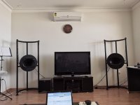
The project consist on 2x 21" subs with down-firing ports tuned between 18~20Hz to replace the current sealed Ultimax UM18-22 ~5FT3 sub, in hopes to target the best of both worlds or at least to be close, to get some deep lows and high impact upper bass with low distortion.

I have to admit this is the first time I work with this kind of large subwoofers, and I want to post here my current design options and get some advice of the owners with success on this kind of subs before deploy the project.
Also like previously mentioned, this is a 99% music setup and I listen to a very broad variety of music genres but mainly rock, oldies and electronic when I'm in the "Moar BASS" mod.

I currently have two own designs which are very similar to the "PSA TV3612" in regards to the port location which is down-firing, unfortunately I can't get them work with single 6" ports without having a lot of air velocity/lots of chuffing when the subs are drived at maximum capacity(regarding WinISD), then my only options here are between 2x 6" ports, one 8" port or a straight slot port embedded in the rear side of the box, so my bias for now is the single 8" down-firing port.

I will post some images of the cartoonish paint draws(sorry I'm not good at drawings 😱) of the two boxes design, one resembles the one with the 8" port and the other with the slot port, while the one with the 2x 6" ports being discarded; the planned box material is to use between BCX, cabinet grade ply or marine grade ply, however since the cost of the marine plywood here in P.R. is way expensive, I guess that I can try and find average quality on probably BCX or cabinet grade plywood and double up 3/4" to form a 1.5" sandwich on all sides.

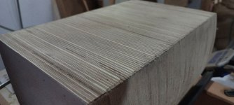
Also here is a material that I'm looking to know if it may be useful for this large sub boxes project, it is called: EB1S White High-Pressure Laminate Plywood Melamine Board, I can also double up those material as well and they look very flat stable and seems to have little to none voids, well at least looks like so at naked eye.😕

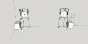
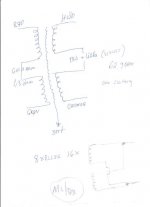
Well to conclude, here are the draws of the enclosure design in question, so what design is more appealing for this 21" drivers:

Measures: 48" H x 24" W x 24" D.
Walls: all 1.5" thick walls with braces.
Finish: Black-mate laminate.
Volume: 11.5FT3 gross, around 9.2 FT3 Net. after port/driver/bracing.


--------------------------------------------------------

Alternative measures using 5/8" sheets:
Measures: 42" H x 24" W x 26.5" D.
Walls: all 1.25" thick walls with braces.
Finish: Black-mate laminate.
Volume: 11.8FT3 gross, around 9.5 FT3 Net. after port/driver/bracing.
--------------------------------------------------------


Design with an 8" down-firing port:
21in_Box_Model_Experimental_v1.png

Design with an back straight slot port:
21in_Box_Model_Experimental_v2.png

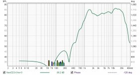
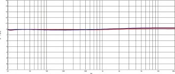
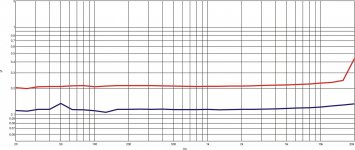
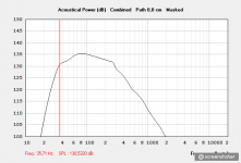
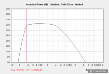
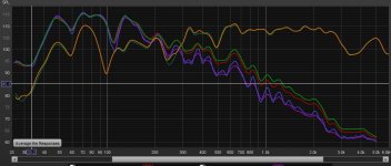
WinISD Maximum SPL and current UM18-22 for compare:
Screenshot from 2021-01-15 22-04-25.png

Regards, sorry for my English.🙄

Woofer calculations Frequency X-max and Voltage

Hi,

I'm building an impuls compensated MFB system with 2 Dayton RSS210HO-8 units.
Put the -3dB point at 30Hz.
I know how to calculate X-max and SPL at a fixed frequency.
VD = 256,6 cm³ X-max 12mm SPL 83,5dB @ 2,83V/1M
Calculation give for a X-max 12mm 30Hz 95,89dB and 100Hz 116,80dB (I know that it cannot reach 116,80dB)
What I like to know which voltage you need to get X-max at a given frequency and how to calculate?
I think it's not as simple as 30Hz 95,89-83,5=12,39dB so it's 11,77V

Rob

Philips SAA7220 Reclock PCB any good?

Sorry folks I know this sort of thing has been covered here but I cant find anything this specific, I purchased this little drop in replacement for the filter chip but I would love to know what it does exactly, I asked the vender and I didnt get a very good response, "it reclocks and buffers the signal and sounds amazing" So I took it apart and drew the connections, I know its a Flip Flop and an Inverter/Buffer but can anyone with experience here say if its actually doing any good? Ive been reading about DEM reclocking and the mighty NOS thread for a while but my head is spinning. :scratch1: When I started the thread title one other thread popped up about the 74hc175N but had never got answered.


Alan

Attachments

  • 2019-04-08_2317.jpg
    2019-04-08_2317.jpg
    137.5 KB · Views: 1,726

TDA7293/94 aliexpress warning

There are several stores selling cheap TDA7293 kits on aliexpress and probably other sites with the note:
The mono power amplifier board chip has TDA7293/7294, which will be sent randomly

That would be fine I guess except that the footprints are not quite compatible; specifically, the 7293 has a dedicated BOOTLOADER pin (12) which drives the bootstrap capacitor, whereas on the 7294, the bootstrap C is driven by the OUTPUT pin (14), and pin 12 is NC.

I received a bunch of these (for an active-crossover system) with PCB layouts that assume a 7293 (bootstrap from pin 12) but the packs included 7294 chips, which I presume means the bootstrap C will not actually charge up, and therefore the chip will probably start clipping at lower than expected power levels. The 7293 I think can bootstrap from the output so it is probably possible to make a board compatible with both chips, but the boards they're selling suit only the 7293, not the 7294.

It could be fixed with a bodge-wire and spot of dremeling, and the kits are still probably reasonable value (similar cost as a single chip shipped), especially if you bin the likely-fake "2200uF 50V 105C" electrolytics and run them off a better DC supply than the little bridge and grossly-insufficient rectifier filter included.

Emotiva B1 Bookshelf speaker Crossover Mod

Hi,


a friend of mine have Emotiva B1 speakers . B1+ is the new updated speaker. Specs looks the same but the sound should be a different. While the speaker is good he said that he misses a bit highs on the tweeters It seems that many have done tweeter crossover bypass mod as this one
`...
I ended up adding a pair of film bypass caps across the tweeter crossover capacitor. That fixed that problem. I used a polypropylene .1 uf 400V InfiiniCap with a .01 uf 630V polystyrene...


Have any of you done this mod maybe ?


Any suggestions other mods?


Best wishes Peter


2Q==

Attachments

  • Emotiva B1 Crossover pic1.jpg
    Emotiva B1 Crossover pic1.jpg
    140 KB · Views: 130

help needed choosing one of these xover slopes ( graphs attached )

dear sirs,

i have taken various measurements of different component values on a 3 way xover I'm creating , these graphs are for the bass + mid only

im not too sure as to which slopes i will select, do i go for the bass slope with higher output in the 200-800hz range , or choose the slopes with lower output in this range? there are 4 different slopes for the bass .... any help appreciated.

ps: the xover point is 200hz ( These are in room measurements using the various components i used )

Attachments

  • sd5 basss + mid mix.jpg
    sd5 basss + mid mix.jpg
    101.2 KB · Views: 167

Diy subwoofer controller (LPF)

Hi Guys.
I have been building a new plate amp for my hifi subwoofer. Its uses a ported box (not sealed) with a 12'' LF driver.
I have been meaning to build an appropriate controller (low pass filter) with volume, freq and phase switch.
I have come up with the following circuit. Most of it is partially copied from a Sony sub woofer schematic that I have,
Will this circuit work??
What are the changes you would make?
Are there any better circuits I could use.
There isn't any reputable schematics online that people have built and tested except for Rod Elliott's P48, but it needs a special box and driver.
Any help will be much appreciated.

Attachments

Hørning MC transformer

Hello. Trying to put together a step up MC transformer using a Hørning transformer but with no luck. I followed the schematic he sent me but no sound comming through.
I use the 16 times ratio with output in parallell and have tried with the input both in parallell and i series. No sound. What am I doing wrong.

Attachments

  • DSC_0065.JPG
    DSC_0065.JPG
    466.2 KB · Views: 181
  • MC Trafo.jpg
    MC Trafo.jpg
    20.2 KB · Views: 175

Alternate First Watt Power Supply Schematic

Anyone know where I can find the First Watt (FW) schematic that allows channel separation via the filter caps?
Saw it somewhere in the middle of a thread.
Looks almost exactly like the standard FW power supply, except a part of the supply rail is disconnected before the last reservoir cap.

Can anyone verify whether or not this version helps with channel separation or is it a "six or one half dozen" situation?

Thanks,

Vince

Pc psu toroidal inductors?

It just occurred to me....

How come PC switching psus use toroidal inductors at the output, after rectification?

Aren't toroidals, which are lacking a gap, supposed to saturate at DC and at the (relatively) high currents a modern desktop PC uses?

I think i've seen toroidal chokes even on older motherboard regulators.

Is it maybe because, they are used right after rectification, where there is only rectified switching DC, and not pure DC?

Any thoughts?
Thanks in advance!

Linn LK85 failure and repair

I snagged a broken Linn lk85 the other day, and when I popped it open, carnage! Both chips had basically exploded. On initial inspection, I couldn't see any other damage. When I pulled the board out and looked at the back, one trace per chip (same one) from pin 8 to pin 15, were fried. I replaced the chips and used a piece of wire to replace the trace, and it is now working fine. What would have caused this failure? Overheating due to bad thermal coupling with the heatsink? Shorted outputs? Only info I got from the seller was that it was working in the basement, until one day it wasn't. Also, this particular lk85 uses tda7294, not the tda7293 as shown in schematics and other threads.

It sounds quite good, first chip amp I have experienced. Now I am intrigued as the sound is quite good, and I am interested in building my own chip amp. Anyway, thought I would post up this failure and repair for reference.

Attachments

  • IMG_20201217_221453.jpg
    IMG_20201217_221453.jpg
    104.4 KB · Views: 729
  • IMG_20201217_212023.jpg
    IMG_20201217_212023.jpg
    113 KB · Views: 830
  • IMG_20201217_182241.jpg
    IMG_20201217_182241.jpg
    119.8 KB · Views: 778
  • IMG_20201211_170848.jpg
    IMG_20201211_170848.jpg
    159.4 KB · Views: 1,375

Posting glitches: asterisk, cloudy bottom

1) I tend to use paren asterisk paren to tag internal footnotes in a post. This evening on a moderately long much-edited post these kept being interpreted as Italic code.

() (*)

2) As the message got longer the bottom got hidden behind a cloud of fog. I have very-very-very little use for "transparent interface", especially when the interface takes priority over my jabbering.

FireFox 95.0.2 on Win7
foggy-----------42.gif

  • Locked
Resolved - Feature not a bug Full screen adverts way too large

Old site - adverts discrete and in scale with site.

New site - adverts in random locations including mid scroll that are the size of the screen height.

Previously the adverts were acceptable now they’re downright invasive and annoying.

it may be the norm in the US for aggressive adverts every 5 minutes but in other countries it’s not. I deliberately make a mental note of aggressive advertising and don’t buy the brand. Much in the same way I avoid Samsung due to selling badly tested products.

Farnell Black Friday Rant (voucher code doesn't work)

Just spent the last 4 hours putting together a component BOM for use with the BFR15 code. £324 after sales tax (VAT). Why 4 hours? Because none of the values of resistors in the right resistance, wattage or type are available..

Does their website accept it or warn what is preventing ... NO. Just "The voucher entered is currently inactive and cannot be applied to your order.".

WHAT A WASTE OF SPACE.

Livid. 😡

And they should throw in a spectrum analyser for my troubles 😀

Not happy. Way to go Farnell UK !

  • Locked
Resolved - Feature not a bug New platform turns text links into images when posted

This phenomenon is difficult to describe, so please bear with me. I have only seen it occur in the Rock Music thread of the Music forum but it could be happening elsewhere on diyAudio as well. Before the moving to the new server members would place links in their posts which, when clicked, took the clicker to the site in the link, usually youtube. The link would be the usual line of text/code colored blue as per attachment A. The post in attachment A is dated December 07/21, two days before the site migration. Attachment B is dated December 11/21, after the site had been moved. It can be clearly seen that instead of a line of text/code in blue for the link, an image of the link destination now appears. I am certain this is not what Soundhappy wanted nor intended. Regardless, as things stand at the moment, when one composes a post incorporating a link in the Rock Music thread of the Music forum, the link line of blue text/code will immediately and irrevocably change into an image the moment the Preview is clicked. Hope the explanation above is reasonably clear. In any case, if there is a way to prevent a line of link from becoming an image when the preview button is clicked I would love to know it. Thanks for listening. Much appreciated

Attachments

  • ROCK.MUSIC.A.jpg
    ROCK.MUSIC.A.jpg
    34.3 KB · Views: 110
  • ROCK.MUSIC.C.jpg
    ROCK.MUSIC.C.jpg
    63.3 KB · Views: 114

Scheduled for resolution Choice of theme when not logged in does not persist long enough

As reported here: https://www.diyaudio.com/community/...-platform-feedback-wanted.380360/post-6878461 member @jbau reporting a limited persistance of the choice suggesting the use of session variable is not long lived enough for the purpose. Using long lived cookies for non-logged in users would be ideal. And database storage of members' settings would be better for multi device usage.

Technics SP15 UFO landed in Scotland 👽

Just taken delivery of another record player I definetly don’t need.

Bit confused as to how to power the thing as yet as it appears to use some sort of switching power supply. I was thinking it would be easy enough to make an external Psu but it wants 168vac that also includes 20khz pulses.

Looking at the power board schematic it doesn’t exactly specify the Ac voltage it wants so I was wondering if these were ever sold in the United Kingdom or if it’s fair game to pipe in 240vac or should I just buy a step down transformer ?

image.jpg
image.jpg
image.jpg
2D596460-267D-4EB4-A1B1-5B551DA012DC.jpeg
image.jpg
image.jpg
image.jpg

Dipole playfields

Hi

So I start my thread now. For years I have been playing around with dipole concepts, just for fun, always with the intention to find some solutions and to feed my curiosity. Learning by doing. Learning by trial and error. Learning by sawing and welding, measing and reading. Like a real hobbyist. And learning by sharing ... and getting answers, like this one:

Thanks for sharing, Daihedz! Perhaps it's time you started a dedicated thread?

When I worked on the baffle design for the 8c I took infinite baffle measurements as a reference point. I looked at frequency response, directivity and the Energy Time Curve. In the ETC irregularities are easier to spot than in an impulse response.

A tip: make sure you are not focusing on very small reflections that happen close to the microphone, instead of baffle edges!

Thanks for this one. I never considered ETC, and indeed, having peeped into it, it seems to be another, for me new and useful information well. And I come to this forum in a hope to share and tap new infos with and from another community than the one I met at www.aktives-hoeren.de, where I was active for some years until now.

DIY-wise, in my shack there actually is a heap of Yamaha AX amplifiers to feed my ongoing-neverending multiway dipole project, some linux-friendly M-audio Delta 1010's soundcards, some drivers, some books, some laptops and the like, but no really operative system. My ongoing project is never operative, because it is in steady transformation ...The last release of a really operative system occurred some years ago, still functional, and since then, there is production-wise nothing happening but joyful construction time again.

For the measurements I use Uli Brueggemann's fantastic Acourate Sofware, for rapid prototyping of Xo's it's Acourate Convolver counterpiece on an old W8.1 Laptop, along with outdated RME Multiface ADDA's

So? This is my actual concept project: A 5- to 6- way dipole. Mutations occur nearly every week-end.

An externally hosted image should be here but it was not working when we last tested it.


When finished, which I hope will never be the case, there will be two units per channel: A woofer two-way unit 60-170/170-285, and a mid-treble three-way unit 285-710/710-2200/2200. Plus maybe a subwoofer elswhere in the room, where it's best suited. Specs and distances from driver to driver are chosen in order to perform the transitions with lobing <1dB (except for the highmid-tweeter xover), and for a target SPL of 110dB@f_crossover@Xmax/2. Not @ Xmax, but Xmax/2, in order to keep distortion low, even at a theoretical volume-displacement-limited SPL of 116dB for the whole system.

So, basically that's it. Little bit crazy, and maybe welcomed weird (as a forum's member wrote). Might be. But no worries. In my professional life I am a shrink. That's maybe one of the reasons for embracing crazy things.

NOS. Sonus Faber Tweeters

NOS Sonus Faber tweeters. I believe these were made by Scan Speak?? 7x Black and 3x Silver faceplate tweeters available.

$30ea, $50 for a pair, plus shipping.

Attachments

  • 20211223_100659.jpg
    20211223_100659.jpg
    420.8 KB · Views: 164
  • 20211223_100718.jpg
    20211223_100718.jpg
    423.6 KB · Views: 176
  • 20211223_100722.jpg
    20211223_100722.jpg
    255.1 KB · Views: 162
  • 20211223_100747.jpg
    20211223_100747.jpg
    310.2 KB · Views: 169
  • 20211223_100751.jpg
    20211223_100751.jpg
    263.4 KB · Views: 167

Citation 12: left channel buzz

I've gone through a Citation 12 and done a partial refurb for a friend, changing out all the passives at his request. I have different thread going regarding the input capacitors, which is another story entirely. I wanted to make a separate thread so things didn't get muddy.

The electrolytic caps have been replaced with new Nichicon KZ or similar, the resistors are now all Dale 1 percent tolerance metal film. I've added some ceramic discs across the regulators, and installed gold 5 way binding posts. The left channel now has a buzz through the speaker - sounds like a bad ground, or a power supply noise, but...

Before I rebuilt this thing the big filter caps were vibrating badly. After the work they're dead quiet both to the ear and to the touch, and so are the transformers. I've also re-flowed all the ground connections I could see, but the buzz is still coming through the speaker. Where could this be coming from?
Projects by fanatics, for fanatics
Get answers and advice for everyone wanting to learn the art of audio.
Join the Community
507,797
Members
7,888,837
Messages

Filter

Forum Statistics

Threads
406,261
Messages
7,888,837
Members
507,797
Latest member
Moza