Hey all, I'd like some feedback on an amplifier I'm building. This is my first time semi-designing an amp, so it would be really helpful for me to have more experienced eyes look at it. Buckle up, this is going to be a lengthy post.
Originally, I was going to build an amplifier based on the schematic shown here:
DHTRob - EL3N Single Ended Sakuma style. It uses EL3N tubes as both drivers and output tubes. But the more I researched, the more I went down the "what if" rabbit hole, and have reached the heavily modified design I have now. I have a bunch of changes to the original schematic from that url. Some of them may or may not be good ideas. I'm still learning a lot as I go, so I'm open to constructive criticism.
The ultimate goal with this project is two things:
- To have an all-EL3N amplifier like the design from DHTRob above.
- Be able to replace my Ampsandsound Mogwai SE by being able to roll the output tubes from that amplifier (EL34, 6L6GC, KTxx family, etc)
Changes to the above design:
- Able to roll 6J5 drivers instead of EL3N drivers.
- Able to roll EL34/6L6GC/KTxx tubes as output tubes instead of EL3N.
- Gyrator loaded input tubes for better support of 6J5. As far as I understand it, I can set the anode voltage with a gyrator. Therefore, I can set the anode voltage to 150 and bias at -4V. This should provide a happy operating point for both EL3N and 6J5 drivers.
- One chassis design rather than separate PSU.
- Switch to change cathode resistor for EL3N outputs and other output tubes (explained more below). Switch may also have to switch between different HV secondaries from the PT due to the way lower current that EL3N output tubes operate at.
- Primarily for headphones. I almost exclusively listen to headphones, but I may also provide speaker outs.
Some specs:
- OPTs: Custom made 5K:8/16/32. 32 ohm secondary will be used for the headphone jack.
- PT: HV secondary will have to be custom if I want to support EL3N output tubes. The current draw in an EL3N-output configuration will be much lower than the other potential output tubes (20mA per EL3N output tube vs ~70mA for others), meaning my resulting B+ will be higher. So something like a 0-320-360V secondary with a switch to switch between 320V and 360V can accomodate that.
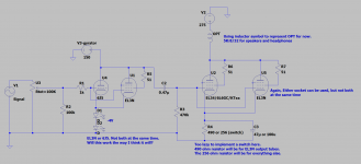
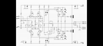
- Current schematic: pic attached.
- LCLCRC PSU for low ripple when using headphones (pic attached).
- This will be a (almost) no expense spared kind of project. So I'm looking at custom made Monolith Magnetics transformers for this project.
- Target B+: ~275V
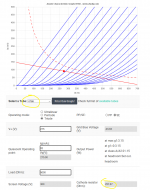
Driver tubes:
Gyrator loaded with anode voltage set at 150V.
Biased at -4V (2 green LEDs?)
- 6J5 driver will draw about 6mA
- EL3N driver will draw about 17.5mA
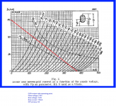
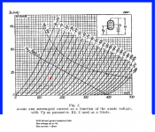
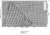
Output tubes:
Will have a switch for the cathode resistor to switch between EL3N and other output tubes as well as the HT value. I'm hoping I can implement one switch that switches both of those things at the same time.
EL3N
- plate voltage: 275V
- bias voltage: -9.8V
- bias current: 20mA
- cathode resistor: 490 ohms
- Total amp draw: ~75mA (20 + 20 (outputs) + 17.5 + 17.5 (drivers))
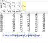
Every other output tube (256 ohm cathode resistor):
I designed these with the EL34 as a baseline. So the specs are correct for that tube. The others will vary a bit with plate voltage and bias current than what's shown here because if certain output tubes draw more current with a 256 ohm cathode resistor, the B+ will go down... and if they draw less current, the B+ will go up. This will in-turn affect how much current is drawn (I think!). I'm hoping that I found a happy-enough medium with the 256 ohm cathode resistor that the B+ variations between these output tubes will be acceptable. The only tube I'm a little worried about is the KT88. I might raise the cathode resistor to bring down currents a bit to get the KT88 in maybe the ~80mA range.
EL34
- plate voltage: 275V
- bias voltage: -18V
- bias current: 70mA
- cathode resistor: 256 ohms
- Total amp draw: ~156mA (70 + 70 (outputs) + (6 + 6 (6J5 drivers)))
KT66
- plate voltage: ~275V
- bias voltage: -18.69V
- bias current: 73mA
- cathode resistor: 256 ohms
KT77
- plate voltage: ~275V
- bias voltage: -15.37V
- bias current: 60mA
- cathode resistor: 256 ohms
KT88
- plate voltage: ~275V
- bias voltage: -23.89V
- bias current: 90mA
- cathode resistor: 256 ohms
6L6GC
- plate voltage: ~275V
- bias voltage: -17.65V
- bias current: 68mA
- cathode resistor: 256 ohms
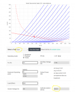
Attached are pictures of the schematic, some of the load lines and operating points for input/output tubes, and an example of a PSU. Again, I'm still kinda new to all this, and there's no way I got everything right on this first try. Any and all comments/suggestions are welcome.
Outstanding questions:
- Is a 6J5 or EL3N enough to drive potential power tubes like EL34 or KTxx tubes?
- Considering my size limit for this amp: I have room for either a tube rectifier (I like the aesthetic) or a potted choke for choke input PSU. Is a choke input PSU superior enough to cap input PSU to justify having?
- Is there any way to estimate the output power this amp will have? I found a couple formulas for output power, and I don't know if any of these are accurate:
-
Of Loadlines, Power Output and Distortion.
-
The Valve Wizard -Push-Pull At the bottom. Though this is for push-pull, and I don't know if it's applicable to SET amps.
- There's also a power estimate on the universal loadline calculator I used, but the power from that is way higher than the previous two. Not sure if any of these are accurate estimates.