Oscillation with D3a tube.

Could be Oscillation with D3a tube and not oscillation with 6e6p tube in the same tube amp.!

The amp is D3a 45 300B tubes.
I think the amp with D3a triode mode ( u =77) sometimes oscillate.

With 6e6p tube with less amplification factor ( u =35 ) i think NEVER oscillate.

Too much amplification voltage could be the cause of the oscillation?

Thanks a lot.

santitrucco

Resolved - Implemented Watched threads should default to showing only unread rather than all watched threads

Got it! A weekly email to let me know which of my watched threads have been updated would go down a treat. Thanks JP.
Should add to the list that watched threads here seems to now be defaulting to all rather than unread, which makes it decidedly less useful.

Power Adaptors / Units for audio uses

Hi. Hope this thread is kosher. Unless I do build a power supply in the end, I may want to purchase a power adapter or unit for a tuner board I have (from a Pioneer F-X77ZL). I'm guessing that board will not take more than 10W. I can identify some power adapters for sale, but I don't think I've yet come across one, or a type, that would be suitable for this tuner board. The adapter or unit needs to have pretty good ripple specs. I'm not sure whether I strictly need a linear unit or not. Are there suitable power adapters or units out there for sale that would be suitable for my tuner board? Thank you. I'm in UK. Rich EDIT: I'm in process of trying to buy a service manual for the F-X77ZL so I can glean wattage and supply voltage.

For those with 3D printers

Flame suit is officially on since this is firmly in snake oil territory. I was looking at those super expensive Furutech cable lifters and shaking my head when I thought why not just 3D print a small riser to hold up my sagging power cable going to my amp. I have my amp on Iso Pucks right now and the power cable was at a pretty big angle so I figured it wouldn't hurt. Measured and printed and I was 10mm over, so I redesigned and got it to fit perfectly. Placed the riser under the power cable right at the amp input and it was perfectly straight and I sat down to listen thinking I'd need to really analyze if I could hear any difference.

Well, what the heck!? Soundstage expanded considerably, bass extension skyrocketed and highs got very bright. I didn't believe it, so I went back and took it out and listened again and honestly I like the sound without it more because I am already used to it. I put it back in and the difference is pretty shocking and I'm going to leave it in for a few days to see what I think after some time. The only explanation I can think of is that the connection was loose originally (it was, the cable was just hanging out at a big angle even though it was fully plugged in) and by adding a support more of the blades were touching the male contacts on the amp. There is no vibration damping involved, just regular PETG filament but I couldn't believe how much just straightening the blades and providing more contact area would impact the sound. Treble is a bit bright for me now, a tiny bit shouty but I figured I'd post this cheap mod for people who have a 3D printer and have amps like mine that don't have an OEM death grip on the power cable. Strangely, my Topping D90 is such a snug fit that I have to strain just to get the cable pushed in all the way so it probably wouldn't do a single thing to that one. Worth a shot, was not a believer and it was a fun experiment and sure beats dropping big $$$ for an 'official' riser.
  • Like
Reactions: StevenCrook

LF drivers for sale, JBL2226J, TD-15M, ALTEC 515B

Greetings all,

Over the years in the hobby, I had accumulated many parts/drivers. Now that I am building the "dream speaker" TM, LOL, with TAD1601A that I acquired, I need do start selling them.

Before I put them on e-bay or other web-sites, I thought to offer them to the members first. As I had never done such, I have been thinking that I would provide history/description, and based on interest/requests, I can take hi-resolution pictures, e.g., with ohmmeter attached to show the integrity/resistance of the voice coil. Please let me know if this is acceptable.

1. JBL2226J, i.e., the 16 Ohm version

I have acquired a pair from Erich H, DIY SOUND GROUP. As I understand, they came from a church installation. I intended to experiment with PPSL, but the project never materialized, so that they were sitting in the shipping boxes ever since.

I think that a fair price would be $500 for the pair shipped, but I am opened to offers.

2. Acoustic Elegance TD-15M, the 8 Ohm version

I had purchased the pair directly from Acoustic Elegance, AE Speakers by Acoustic Elegance. I had measured both of them for T/S parameter, which I perhaps may still find. I built an enclosure and one of the drivers was briefly mounted and measured. However, shortly afterwards I acquire ALTEC 515B, which I had re-magnetized by Great Plains Audio, Home - Great Plains Audio, and briefly used them in the cabinets.

Since the woofers are essentially new, I think that a fair price would be $850 for the pair shipped, but again, I am opened to offers.

3. ALTEC 515B

I am not quite sure whether I really want to sell these, but, I am still putting them here for a consideration.

The drivers were acquired by an exchange from the late Dr. Bruce Edgar, and as noted above, sent to be re-magnetized by Great Plains Audio, Home - Great Plains Audio. I used them in the above-mentioned cabinet for a while. Unfortunately, the drivers have not performed in the cabinets, so they were removed and stored.

If there were serious interest, I would have to ask for $3000 for the pair, and I will not negotiate. Unlike the previous drivers, which are still available/produced, the 515B's supply is limited, furthermore, given the AlNiCo magnet, even the currently GPA produced have been steadily increasing in price.

Please let me know if you have any questions.

Kindest regards,

M

Trying to reduce distortion on an old Heathkit IG-72 signal generator

I've been working on a Heathkit IG-72 vacuum tube signal generator for fun, and as a learning experience. So far I have had much success. I've cleaned up all the switch contacts, installed NOS replacement tubes, replaced the electrolytic capacitors and all the 5% resistors (besides those in the attenuator). The wave output is now clean and stable across the full frequency range. However, I am not able to achieve the specified distortion figure of "Less than 0.1% from 20-20,000 Hz".

Through experimentation, I have found that the oscillator control is very sensitive, and only produces a clean signal in a small fraction of it's 600 Ohm range, less than 100 Ohm. Minimum distortion, about ~0.75 THD, is only achieved at the very lowest portion of the range, about 10 Ohms. Any lower and the signal drops out entirely. Any higher and distortion begins to rise. At this low end of the range, output voltage is reduced to about 1/10th of the expected ~3V.

This leads me to believe something is wrong with the circuit. I wouldn't expect the oscillator control pot to only provide clean output in such a small range, at the very least. At this point, I'm not sure where to turn.

I am getting what I take to be transformer whine at higher voltages. It varies in frequency/pitch as I adjust the controls. I think it's coming from the smaller of the two transformers.

Here is the manual: https://www.manualslib.com/manual/1854974/Daystrom-Heathkit-Ig-72.html

I did my distortion measurements using Room EQ Wizard through a Focusrite Scarlet.

Extra transformer wires

A lot of transformers have a bunch of extra leads. Which is fine. You can cut them off if you want, but if you decide to use the transformer for something else down the road, you're pretty hosed. Typically, you'd cut the leads short, but accessible, and tuck them away somewhere. Is there any reason you couldn't remove the end bells, and (assuming there's space) tuck them up in there (also assuming they're well insulated)?

Speaker surround foam or rubber can't find?

I have some Speakerlab 9 speakers I got cheap at the Goodwill, they actually sound great but the speakers need new surrounds and the problem is finding the right size.

I've tried ordering two times now from amazon but they are just a hair too big to fit the inside cone.

The outside diameter tip to tip is 6" but the inside diameter (measuring from old speaker) is 100mm or 3.93", this is the part that sits inside the cone.

I can't find anything meeting these diameters for the inside cone.

Any links to who might have these, within a price reason, would be appreciated. I currently have some spare 8 Ohm speakers in their place, which sound good but the originals were 6 Ohm.

Need advice: building Troels Mini Bookshelf, will add Woofer stand. Will this work?

Hello,
  • I had an old pair of Seas W15CY001, so deciding to follow Troels' mini : http://www.troelsgravesen.dk/SEAS_5INCH.htm
  • Later I would like to add 8" woofer separately for each chanel as speakers stand, woofer will be side mounted.
  • I possibly use Seas H1192-08 CD22RN4X
  • Woofer will use passive crossover. Connected to main speakers with external jumper. So these will work with single stereo amp.
speakerdesign.jpg


  • Will the woofer works with this cabinet volume, and with this mounting?
  • Since the crossover for woofer is passive, is there anything that allow me to adjust and change the level (woofer), like volume control?
  • Any example of crossover, build guide would be appreciated.

Sorry if any part does not make sense, I have not much experience building speakers.
Any advise would be appreciated.
Cheers,

irs2092s-based 2000W Amplifier? ("iraud2000")

While searching for a rather high wattage, high efficiency amplifier for a new project, I just found this:

Top iraud2000 d amplifier finished board high power 2000w irs2092s digital amplifier board on Aliexpress.com

What do you think of it? Is that bridged-mode rating "2000W @ 4 ohms" realistic? Would the transistors need some replacing in order to achieve that rating long-term?
Any better high-efficiency alternatives that can output 70...90V into 4ohms without being super-expensive? The system is high-voltage battery-powered. I want to avoid any large switching power transformation if possible.

Kind regards and thanks so much for your thoughts and ideas,

meko

Rockford Fosgate Punch 40.2

This amp appeared to be OK. It powers up and produces +22.60vdc and -22.63vdc. I input audio and it produces, but there seems to be some static or distortion. I disconnected audio and started checking.
What is an acceptable deviation from the norm on the +/- 15 volt supply?
Q8 is outputting 14.21 and Q9 is outputting -12.99.
Q8 "adj" voltage is 12.96
Q9 "adj" voltage is -11.73
Could this be part of the problem or what else to I need to check?

Bose PS321 II powered subwoofer - acoustimass connector pinout

Hi,
I got this sub woofer without any other accessories. It has acoustimass square connector as attached. Its a square connector with 13 pins. One is 27V DC and one has 2.4V. Rest of them reads 0 V. I am trying to find the pinout diagram for this. Internal circuit has DSP so it is not that straight forward to find connections. Can some one help me finding pinout ? My final target to use this subwoofer as another subwoofer in my sound system. I still hope that this unit has analog input. If it is digital, then I am screwed.

Thanks,
Pubudu

Attachments

  • acoustimass.jpg
    acoustimass.jpg
    8.4 KB · Views: 848

"natural" material for room acoustic treatment

Hi all,

So we all have used Rockwool or glass fibre for treating rooms etc... but now that more ecological, healthy materials are available, what do you think of them?
For example :
- Recycled newspaper panels with density of 32-42 kg/m3 available here in Finland (Ekovilla)
- Recycled cotton with density as low as 20 kg/m3
- Hemp
- Wood
- Sheep

What do you guys think when it comes to treating room and especially bass trapping

In Finland Ekovilla slabs (32-42 kg/m3) hasn't been measured but their blown wool of similar density has AFR of about 10 kPa*s/m2.

Manu
  • Like
Reactions: jamesblonde

Help understanding bandpass XO weirdness

Just trying to learn about this and I find there are at least four ways to do it.

Looking from source to driver:

1.series cap, series coil, parallel cap, parallel coil

2. series cap, parallel coil, series coil, parallel coil

3. series coil, parallel cap series cap, parallel coil

4. series cap, series coil, parallel cap, series coil

They all appear to use about the same values for caps and coils.

I assume they all would work, but is there any real electrical or audible difference?

ZEN-like headphones amp

I've built a scaled-down version of the Zen amp to feed my Grado headphones.
The HexFets employed are the usual IRF610, both for the active side and for the current source.
The bias current I chose is 300mA, the power supply voltage about 30Vdc, for the maximum compatibility with Hi-Z headphones.
I've obtained best results taking advantage of Nelson's patent 5,710,522, this allows to halve the distortion figure and to increase the drive caapability: on 32 Ohms load I've measured over 8Vp-p without any apparent compression, as soon as possble I'll perform a standard measuring set.
The sound is beautiful, more natural (notwithstanding Grados..) than the RA-1, which is not that champion people believe, at least in my opinion...
😉
The input impedance can be set between 13KOhm ( freq. respnse as far as 80KHz) and 40KOhm ( upper -3dB limit 26KHz).
If someone would desire the schematic, I'll send it to him gladly.

Finished project (3-Way Horn)

Hello, these days I have finished my first project with high sensitivity drivers and I wanted to show it to you.
I am very grateful to this forum since through it I have learned enormously, thank you.
The drivers chosen for the project are the following:
-Faital HF108 on B-52 PHRN-1014 Horn
-Faital 10PR320
-B&C 15 PS100
The midwoofer is housed in a closed box of about 14 liters. For the woofer I chose a bass reflex box with an approximate volume of 100 liters.
It is an active multi-amplification system commanded by the minidsp 4x10HD.
I am currently measuring the speakers with REW and adjusting crossover filters and EQ.

Regards.

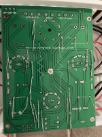
_DSC5343-1 by Ivan Pelaez, en Flickr
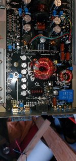
_DSC5335-1 by Ivan Pelaez, en Flickr

[url=https://flic.kr/p/2jCoQgV]
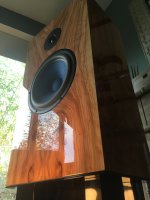
_DSC5338-1 by Ivan Pelaez, en Flickr
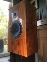
_DSC5351-1 by Ivan Pelaez, en Flickr
IMG_20200625_131638 by Ivan Pelaez, en Flickr
IMG_20200705_101158 by Ivan Pelaez, en Flickr
IMG_20200705_101333 by Ivan Pelaez, en Flickr
IMG_20200705_101517 by Ivan Pelaez, en Flickr
IMG_20200710_172850 by Ivan Pelaez, en Flickr
IMG_20200716_194107 by Ivan Pelaez, en Flickr
IMG_20200807_155736 by Ivan Pelaez, en Flickr
IMG_20200825_161242 by Ivan Pelaez, en Flickr

HV Tube bench power supply

Hello all
I’m hoping to get some help on a project I’m looking at doing. I want to build a bench power supply for my LAB that will provide a variable DC supply at about 100mA from a 240v ac supply from my bench isolation transformer.

The reason for this supply is to test valve amp projects before building the final circuit. I wanted the supply to be variable from about 10v to the full 300v dc.

I have already constructed one design attached in image 1 below which for voltage control from 0v to 300v worked very well. However I have found that the output voltage can swing high when switching on as it is unregulated. I tried the circuit powering a heater element at 45vdc and when switching it on the voltage spiked to 55vdc then back down again. This destroyed the valve filament.

I am looking at the other circuit in image 2 which is a regulated supply. Has anyone built this and is it stable. What sort of output current could I get from this circuit.

I have an idea to build the first unregulated circuit for the plate voltages as this can be fairly unregulated, and then the second circuit for the heater elements at a lower input voltage about 80v ac.

Any help would be much appreciated I am a newbie to this I have experience with HV circuitry but not with designing the circuit.

Attachments

  • image 1.jpg
    image 1.jpg
    27.7 KB · Views: 1,749
  • image 2.jpg
    image 2.jpg
    52.6 KB · Views: 1,608

Fine crackling noise with RPi3 (Volumio) an Amanero-Cronos-Buffalo

Hello everyone.

I run a Buffalo-IIIsePro38 and run it with a Amanero-Cronus input. It sounds superb when I play music through my laptop connected via USB. However, when I use my Raspberry Pi 3 running Volumio (3.198) to play music a faint crackling noise is constantly present.

I already tried different power adapters, usb cables and settings in Volumio, but the crackling stays the same. Does anyone know this issue and can help out?

Best,
Stefan

YARRA Preamplifier Custom Case at Modushop

Hi Folks,
Just wanted to let everyone know that we have managed to get a very good deal on a custom case for the Yarra preamplifier.

Here is a PDF CAD drawing:
https://www.diyaudio.com/forums/att...melbourne-db-buy-yarra-preamplifier_gx383-pdf

746162d1553887745-yarra-preamplifier-hpa-melbourne-db-buy-yarra3-jpg


JPS64 came up with a superb mechanical and electrical design for this beauty. For a limited time, Hifi2000 (Modushop Italy) will be providing these for 100 Euro plus shipping (circa 20 Euro to USA). Once they have at least 22 orders placed, they will begin production.

You can read more about the details in the main Yarra preamp thread, but here is the GB interest list as it stands:

xrk971 - 1 case - USA
JPS64 - 1 case - USA
gary s - 1 case - Australia
Vunce - 1 case - USA
windwardmt - 1 case - USA
TungstenAudio - 1 case - USA
Meanie - 1 case - Singapore
Roundtoit - 1 case - USA
mordikai - 1 case - USA
afoor - 1 case - USA
Big E - 1 case - Canada
TboneAK - 1 case - USA
Sampsonite - 1 case - USA
jwjarch - 1 case - USA
batty - 1 case - Australia
MD_Stryker - 1 case - USA
jhofland - 1 case - USA
BEYoung -2 cases - USA (if possible)
ZUM911 - 1 case - Australia
Kokanee - 1 case - Canada
bk856er - 1 case - USA
BRN - 1 case - USA
urien - 1 case - USA

TOTAL = 24 cases

If you are interested, you can place your order online directly woith Modushop and they take care of all the logistics of payment and shipping. We just did the design and marketing for them. A big thanks to JPS64 for arranging this sweet deal with Hifi2000.

YARRA PreAmplifier Chassis

Boot delay board for common ground amplifier ?

Hello,

I am building my first class D amp (5.1) and I am a bit confused about protection board.

I've used 3 stereo TPA3116D2 boards (Chinese one) and I also has bought 3x UPC1237 Chinese protection boards.

I am not really concerned about speaker protection, my main concern is the boot delay to avoid that big pop when I turn on the power.

First, I wired the UPC board as they are meant to be but as soon as I cranked up the volume, protection relay was triggered. It's seem to be caused by the fact that the TPA3116D2 board use a common ground. Vendor say that I need to use one protection board by channel.

So, I then try to only connect L+ and R+ to the UPC board and connect the two grounds directly to speaker. It didn't make the UPC to go in protection board anymore but left and right channel output the same sound.. I don't really understand why..

What can I use as a boot delay for these TPA3116D2 chinese boards ? I don't want to use 6 UPC1237 boards because of the space.

Thank for help.

MetroSound ST20 amplifier hears the sound when the power button "pops"

Hello friends.
I have a MetroSound ST20 amplifier that has a "pop" sound when the power button is turned on, when the volume is turned down, the left speaker is still very low.
In your opinion, how to solve this problem.

Attachments

  • z1822329027508_e102fb3e9a2960d70d21594408b14d23.jpg
    z1822329027508_e102fb3e9a2960d70d21594408b14d23.jpg
    859.7 KB · Views: 489
  • z1822329178802_c2f1cbb8c9bcd739cca29134dae8dcbf.jpg
    z1822329178802_c2f1cbb8c9bcd739cca29134dae8dcbf.jpg
    558 KB · Views: 575
  • z1822329193051_94ee9bcf6b3f7f259d5439ddaf7bd25a.jpg
    z1822329193051_94ee9bcf6b3f7f259d5439ddaf7bd25a.jpg
    510.4 KB · Views: 468

Teac AH-500 PS ripple: fine or too much?

I have a TEAC A-H500 amp which has some slight hum. Suspected a power supply problem; scoped it and found approximately 50 mV 120 Hz ripple under the load.

The 4700 uF filtering caps looked bloated so I replaced them with the new 5600 uF; however, both ripple and hum didn't go away. The attached picture shows this ripple for positive and negative rails going into power amp PCB after capacitors replacement; it looked the same way before.

The A-H500 amp is sort of high-end-ish; however, it was made in late 1990s and few components inside look cheap so it's possible they saved on a power supply.

Is it normal for amp's power supply to have such 50 mV ripples? If not what could be wrong, or perhaps it's some easy way to improve this PS?


Thank you.

Attachments

  • TEAC AH-500 pic_25 Jul 20_a.jpg
    TEAC AH-500 pic_25 Jul 20_a.jpg
    470.4 KB · Views: 212
  • AH 500 PS_Schematics.jpg
    AH 500 PS_Schematics.jpg
    224.2 KB · Views: 242

Let's talk about this 'Marantz Model 7' board on eBay

Hi, has anyone got one of these? It's the phono stage from the Marantz model 7... or so the ad says. Comments? Experience?

Thanks!
(edit Feb 10 - added schematic provided by vendor)

Attachments

  • eBay Marantz 7 phono stage.png
    eBay Marantz 7 phono stage.png
    270.8 KB · Views: 477
  • M7-PHONO-RIAA.pdf
    M7-PHONO-RIAA.pdf
    54.2 KB · Views: 264
  • MArantz 7 PCB layout.jpg
    MArantz 7 PCB layout.jpg
    46.7 KB · Views: 309

Curve Tracer of LockyZ: Better UI and Translation

Hi all,

Since 2014, Lokcy_Z from China released his transistor curve tracer system, and that helps DIYers a lot. The tracer is powerful and inexpensive, and it seems there is no competitor at its price band.

After the production of first batch, the tracer was discontinued for many years. Until 2019, when Locky_Z announced to re-start the production. The new version has smaller formation and some improvements. The ADC and DAC are actually the same, as well as the software.

From early 2020, I got the new tracer and found out that the software have some bugs and poor English translation. Then, I started my work on optimizing the tracer software. Basically the terminology has been re-translated, so that it is much easier for international users. But translate the manual is huge task that I haven't done yet.

Right now, the software version is V3.5.30, in this version there are 2 important changes:
1. The color of curve tracing area has been change to white and blue, etc. This makes UI more friendly and readable.
2. The stamp of lockyZ's logo has been removed, and this helps when copying traces to clipboard and looks cleaner.

You can download the software
here
or go to:
ElecFi Makers: LKZ Tracer ICT V3.5.30i

Any suggestions are welcomed.

Attachments

  • 119774013_2639304596332851_5536774781925275812_o.jpg
    119774013_2639304596332851_5536774781925275812_o.jpg
    472.1 KB · Views: 1,006
  • 119684137_2639305389666105_5658522367848383232_o.jpg
    119684137_2639305389666105_5658522367848383232_o.jpg
    433.2 KB · Views: 1,024

Price increases of basic components

I used to use Dale/Vishay for my standard 1/4W 1% metal film resistors, until, a few years back, Mouser starting pricing them at more than 50 cents each.

KOA Speer were a good alternative, decent quality and only 3 cents ea. in 100 pcs quantities.

Now Mouser has jacked up the price 300%, to 10 cents each. Oh, and they won't be restocked until February 2022.

Maybe that doesn't sound like much, but it adds up. I buy a lot of resistors.

/rant

Sup

Hello,

I am joining the forum to learn more about audio. I have made some boards in the past (ECG, EEG ) and wanted to get back into hobby DIY electronics.

My goal is to learn about microphones and ultimately redesign circuitry for the mic capsule from DIY perks and the MS Alice.

I like forward to my time here 🙂

Are these REL T5s fixeable?

I contacted REL with no response.

So, got two T5s locally from a guy. I asked him if they were working fine before driving to him. He said yes. Drivers look new, cosmetics are pretty decent. I couldn’t try them because he didn’t have power cables and they were at his work with customers being there wouldn’t be easy anyway.

Came home, both are dead. No power whatsoever. Not a fuse issue (put new ones, didn’t work) Though check out these two boards. Both have the same kind of leak or whatever it is. Do you think this is the problem? Would it work if these were replaced? I am not good at soldering but I have the tools. Just would need parts. Though, it is pretty narrow there.

The seller says he will take them back but wanted to see if this could be the problem definitely and/or if it is worth the hassle. Thanks.

Attachments

  • 36884723-62BF-4C2F-B665-6C477A749816.jpeg
    36884723-62BF-4C2F-B665-6C477A749816.jpeg
    128.8 KB · Views: 313
  • A004E6B8-8CED-4637-B174-7DCFD29E3017.jpeg
    A004E6B8-8CED-4637-B174-7DCFD29E3017.jpeg
    168.7 KB · Views: 283
  • 3F418158-1100-49C8-886E-7EF14F7DF176.jpeg
    3F418158-1100-49C8-886E-7EF14F7DF176.jpeg
    189.6 KB · Views: 295
  • 430D4205-B401-4A8F-B3FA-999B4E4ECB91.jpeg
    430D4205-B401-4A8F-B3FA-999B4E4ECB91.jpeg
    221.3 KB · Views: 303

6v6 PP UL bias point

Hello,

After some solid state-years I just rediscovered the magic of tubes 😉

Here's my cheap re-entry, bought 2nd hand: Dynaco 6v6 Push-Pull tube amplifier – Boffin's blog

Time to tinker...

First off, I could really use some pointers for a good bias point. The schematic is in the link, but the measured voltages are much higher: 330V cathode/anode 6v6, 20v bias, 40mA/tube. Seems quite hot.

Any recommendations, keeping the cathode bias and UL arrangement? It sounds good already, but I'll dig up some better caps and tubes as well as rebuilding the PS. Running fine without nfb.

Thanks,
Simon

Seas P18 RE-RA H1398-04. 6.5" polycone woofers FS

I purchased 2 pairs of these maybe rather too prematurely and it would seem I dont have the room for them.

I have the data sheet to share and I shall attempt to link to the thread I started about these.

Edit....link here...
Uses for these Seas 6.5" proprietary drivers

Drivers are brand new unused. One has had a wire soldered on for testing.

£25gbp per pair.

Thanks

Attachments

  • 20191023_215439.jpg
    20191023_215439.jpg
    671 KB · Views: 235
  • 20191023_215445.jpg
    20191023_215445.jpg
    697.7 KB · Views: 206
  • 20191023_215534.jpg
    20191023_215534.jpg
    869.7 KB · Views: 242
  • 20191023_215545.jpg
    20191023_215545.jpg
    466.4 KB · Views: 232

Please help me with my first 3-Way (pro drivers) speaker

Hi everyone,
I have a plan to design an active 3-way using DSP. My reference is Genelec 1238. The speaker will be studio monitor for my upcoming studio.

I have success with 2-way system before using B&C DE250, B&C 12PLB100.

But 3-way is something more challenged that I am interested to try. Due to the unique waveguide of Genelec 1238, I dont think I can find a similar waveguide so I will rely on available parts on internet.

My general purpose is a speaker with:
1. High power handling to use as a main monitor (2-5m listening distance)
2. Accurate and effortless transient response in the whole frequency range
3. Using waveguide at least on HF unit to control directivity
4. Can reach down to 30Hz in-room effortlessly
5. It will be flushmounted in heavy brickwall
6. It can play really good at even low or medium SPL (75-95 dB SPL at the listening position)
7. Due to the room is normally small 20-35 m2 maximum, the speaker will never need to run at full power

My driver choice currently is:
1. 1" Compression Driver: B&C DE250
2. 8" Midwoofer: B&C 8PE21
3. 15" Woofer: This is the unit that I am not decided yet. My current selection list is: B&C 15TBX100, 15NBX100, 15NDL88.
4. Waveguide: I did not finalize on WG choice, too. My current plan is SEO-8 or SEO-10

Could you please help me to choose appropriate drivers and waveguide?

I prefer B&C drivers as I have great experience with them before. My budget for LF unit is around 200-300$. I prefer woofers with high motor strength, low enough moving mass, coated cone and has demodulation ring. I really need the dry, tight and focused LF transient sound.

Thank you very much.

EF2 output stage with 2SJ76/K213 as driver

Was looking at a Kenwood car amplifier from the 90s. The output stage consisted of a pair of 0.5 A MOSFETs and 20 MHz Sanken BJT output transistors.

Looking at the data sheet, the input capacitance is highish (120 pF) and the equivalent fT only about 15 MHz.

https://www.web-bcs.com/pdf/Hit/2S/2SJ76.pdf
I can see the attraction of not having beta droop loading the VAS and possibly some positive TC (not sure this is the case here) stabilizing the idle current, but in terms of bandwidth and nonlinear capacitance, I suspect many bipolar drivers will be superior. Your take?

Consonance Calaf, repairs and mods

I see there is no thread on the Calaf here yet.
Thought I'd do something about it 🙂

I have seen totally 4 of these amps.
They have a very failure prone adaptive bias system.
One had tubes on the input...rest only had the PGA2310 volume control chip.
Sound is decent and there is plenty of power.

One of the calafs had "only" a bad solder joint on what is called the "distortion board". Rest had one channel smoked.
The distortion board is the size of a stamp, SMD, 4-layers and limits BIAS in idle.
Consonance does not provide a schematic of this board, for the others they do.
It is quite impossible to fix.

One I got so tired of that I built Krell KSA-100 boards in it.
I think this was an improvement from the Calaf circuit.

During the weekend I tried replacing the distortion board with 5 1N4148 diodes and a 100ohm trimpot.
Need to bias the amp to about 0.5A to reach -90dB dist. levels.
Originally power transistors are biased to only 3mA each = 18mA.

I am happy with the sound of this modified Calaf. Bias is not easy to adjust though. Started amp at 300mA and after some time it was over 1A. After reducing bias a few times it seems quite stable at 500mA...but I can only imagine what the warm up time will be next time I switch it on 🙂

If someone needs schematics or spare parts I can help 🙂
I'll try to post some photos of my creations too.

balanced high pass line level filter - basic Q's

hi - (very 'basic' q's - very grateful if anyone can bare to answer, thanks.)
I'm looking into experimenting taking bottom end off my mains (8'' 3 way; ellam flex 3) so just my sub is left to the 'subsonics'. I've heard a good way of doing this is simply via a input cap to amp - NC400s (inZ 104K).

Q; I'm running fully balanced so presume a cap is required on the + and - ?? (as i've suggested in diag)

an online calc has given me the values on pic - just checking i haven't made some schoolboy error? looking to roll off from 40hz down initially - its easy to cheaply add another cap to increase this value and push the point lower. (thinking of la clanche sig path caps)

p.s. apologies if i'm using wrong terminology 'c.30 Hz' as in 'circa'

many thanks if you can assure me I am on the right track or otherwise

R

Attachments

  • P1020752.JPG
    P1020752.JPG
    400.3 KB · Views: 115

Onkyo transformer

Hi

Not sure if this is correct subforum, but, I have two questions and here they are...

I have a transformer from dead onkyo tx-nr414 that I want to reuse, now, it has 40/0/40 and 10/10 leads. From 40/0/40 Im going to power mosfets in half bridge and I want to use 10/10 for powering everything else. My question can I connect GND connected to center tap of 40/0/40 after rectification to GND that will be created after rectifying 10/10?
Second question is, I want to provide some protection to speakers and I can see onkyo has relays for that purpose but they are controlled from MCU, is there some standard way to provide overvoltage and overcurrent protection? Over voltage I know how to do but for overcurrent I would have to put some current sensing resistor in speaker path and Im not sure this is the correct way.

Thanks.

Marantz CD 94 110v conversion

Hi all,

Sourced a UK model which has 220v and 240v operation. For it to work in US I used a step down convertor of 110v. Looking at schematics am confused and wondering if this would be as easy as rewiring or not. The transformer part is the same but I see the switch is different. Any guidance if I can wire it to 110v. The relavant part of the schematics is atached

Attachments

Wharfedale D310 mini monitors

Wharfedale D310 mini monitors in walnut finish.
Almost brand new, only a few weeks old. About 50 hours of play time.
Will come with everything it came with when new, including factory packaging, owner's manual and grilles.
No cosmetic blemishes, they are as new. From non-smoker household.
Surprising amount of bass in my 16 x 10 listening room.

$100
Will ship UPS Ground for $25 flat anywhere within lower 48, with tracking and insurance.
Thank you for looking.

fullsizeoutput_add.jpeg


fullsizeoutput_adc.jpeg


D310_walnut_6_1500x.png


D310_walnut_7_1500x.png

Grounding in this tube headphone amp...

Hello,

Still on my journey to recover long lost knowledge...

This time I am analyzing various circuits to understand how they are grounded.

Today, this one:

IMG_1149.JPG


The plate under the PCB is metal.

Here is what I see:
  • The IEC inlet ground tab is not wired to the metal plate.
  • Input signal ground doesn't appear to be wired to the PCB.
  • (unrelated to grounding) The headphone output jack appears to be wired to the preamp outputs.
  • (unrelated to grounding) Input signal wiring bypasses the PCB.

Now, this design/build appears to be a newer version of this one:

IMG_1147.jpg


This build seems to wire input signal ground.

Now, the other side of the board:

IMG_0335.png


I see a star grounding pattern. And that center point connects to the bottom metal plate via a standoff.

Finally, the schematics:

IMG_1155.GIF


My questions:
  1. Why should they not connect the IEC inlet ground tab to the bottom metal plate?
  2. How could they not connect the input signal ground to the PCB? (???)
  3. (unrelated to grounding) Is it OK to piggy back preamp out on the headphone out?
As usual, please forgive my ignorance, I am just trying to figure out the best practices, but and I definitely have much to (re)learn!!!

Also, if there is anything else that catches your attention in this circuit/build, please do share.

Attachments

  • IMG_0335.png
    IMG_0335.png
    1.7 MB · Views: 119

Shuguang Classic and Premium Grade Tubes

Hi

I have just bought a quad of premium grade Shuguang CV181 treasure tubes.

I see there is a classic grade available also, is there any way to tell the difference between the two grades?

It is my understanding that the premium come in at least pairs in a fancy box and that the classic grades can be bought singularly in a not so fancy box.

Also I see the ones advertised on eBay which are sold singularly have three upside down "A" markings as shown in the image below

https://www.aliexpress.com/item/4001028661529.html
Whilst those sold as premium having the writings on them as shown below;

https://www.hotroxuk.com/psvane-black-treasure-cv181-z-gold-grid-matched-pair.html
Can anyone confirm that the ones with the three upside down "A" markings are classic grades only?

Any help greatly appreciated.

Strange Tube Preamp Hum Issue..Help

My Zero Zone Preamplifier has a strange hum problem. I swapped tubes, dropped the AC ground, using a test probe tried to rearrange ground connection. Only does it on Right channel. Is not volume control dependent. Does not increase as volume is raised. Same hum whether source connected or not. As you can see in video, hum increases only on this channel as pencil is introduced. Any ideas?

YouTube video:

Login to view embedded media

TRIBUTE transformers

Hello,

I have TRIBUTE transformers as follows:
INTERSTAGE FINEMET CORES 1: 0.8, current 20ma, 130Henry, 639 ohms, 307 ohms (2 pieces)
SE LINE OUT FINEMET c core, Prim. imp. 20K - sec. imp.790R (4: 2.5), current 10ma, prim L 160Henry, 540hms, 380 ohms (2 pieces).

Please can help me to determine the approximate value for the listed good transformers.
Thanks in advance for your reply.

Best regards from Croatia
MILIVOJ FAFANĐEL

BTSB Panel Mount SE/Bal to SE/Bal Buffer Build from Wisconsin

It’s been a while since there’s been a “from Wisconsin” build thread, so I thought I’d get another one started.

In this discussion, I will be documenting the build of my “Best Thing since Sliced Bread” panel-mounted buffer provided by @xrk971 at XRK Audio. It is a buffer stage that can perform single-ended to balanced conversion and back. Since I’ve been trying to build a system that is balanced when possible, this was a cool tool to have in my toolbox. Details on the product can be found here:

https://www.diyaudio.com/community/threads/btsb-buffer-se-bal-to-se-bal-buffer-gb.358142/

I bought four PCBs and enough parts to create them for an upcoming project that will have four buffered inputs and could allow for either balanced or unbalanced sources. After a thorough inventory and marking of parts, I embarked upon a journey of SMD unlike any I’ve yet to experience. I read through the entire discussion above, closely reviewed the circuit boards, and the decided how I was going to attack the build.

1641339698110.jpeg
1641339725569.jpeg
1641339734455.jpeg
1641339743304.jpeg

Phono grounding

My vinyl equipment consists of a modified Lenco turntable and a Hagerman Cornet3 phono preamp. I have had a long standing grounding issue that is presented as noise from the speakers when I touch the tonearm. As far as I understand the reason for this is quite simple, the power supply that came with Cornet is a wall wart type, with a 2 prong connection. Meaning there is no ground. I have checked that I have continuity from the tonearm all the way to the mains connector on the phono amp.

I must be missing something, how should I get this grounded if the power supply doesn't have a ground pin?

Budget turntable that can compensate for high AC voltage (~130VAC)

My Crosley C100 has a ground loop issue and frankly between its built in preamp always having problems and the fact that I have to adjust the speed (usually in the negative 4 to 5% range) I'm kind of over it

Looking for a ~$200-300 turntable that can deal with my utility's crappy power quality (last I measured was about 128VAC and there's regular flickering) and adjust to the correct speed on its own. Honestly my vinyl collection is pretty old and ratty and this turntable is in the kitchen so I don't need the last word in isolation or sound quality. Any suggestions?

Audison vrx 1.500.2 relay clicking sound

The amplifier is Audison vrx 1.500.2. I've rebuild the PS section .Nothing shorted or burnt in output section.
Amp starts fine, green light, after 3 seconds RL1 (relay 1 which is nais tq-12v), or something around it starts multiple clicking, buzzing and producing awful sounds and I mean loud sounds.
Amp gradually draws more and more current and I look quickly to turn it off. Can't find anything heating up.

Removing RL1 (relay 1) nais tq-12v - removes the awkward clicking and amp draws 1.3A stable.

I've found partial schematics for the earlier revision Audison vrx 1.500 (not the Audison vrx 1.500."2") in the thread over here:
https://www.diyaudio.com/community/threads/audison-vrx-1-500-2-clamps.299921/
Am I being right that this relay turn on the output stage ?

Any ideas what to look for ? Rail voltages are fine +-70v.

Question for Perry Babin.

Hi Perry! How you doing? I have a question Sir. I have and old infinity 611a amplifier. Amp is working good and no problems I had it installed on my car but couple of days a go opened it to clean the internals usually i do this from time on time with some computer air can.Well I find that 2 capacitors are swollen so before they blew and make it worst I plan on replacing them one is 10uf and the other is 33uf both BP and 100v so I was reading this that you posted on this thread.


Hifonics mono amp with non polarized capacitors brz1700.1d


"The series caps EACH have to be able to withstand the full rail voltage. One is always reverse polarized and when reverse polarized, it drops very little voltage. Virtually all applied voltage is applied to only one cap at a time. In practice, in the amps that use reverse series caps, the individual caps are rated for 2x the maximum voltage that will be applied (2 series 200-250v for an amp with ±80-100v of rail).

I use 10uF film caps to replace 10, 22 and 33uF BP electrolytics."

Well the question is can I use a 10 uf film capacitor to replace both of the swollen caps? I see you recommend a panasonic 10 uf 250v 105° to replace the electrolitics, this same cap can be used to replace a 22uf 250v BP capacitor too? Last question is for a hifonics amp capacitor.

Attachments

  • 20220203_173212.jpg
    20220203_173212.jpg
    371.9 KB · Views: 163

Accepting both mono and stereo 1/4 jacks without a switch

I want to make an instrument amp with a 2 channel amp board that I have, that will drive two speakers.

I would like to have a single 1/4 jack input, that can accept either:

1) a mono 1/4 jack cable, in which case, the signal gets duplicated to both channels

2) a stereo 1/4 jack cable, in which case, each channel

Is there a way to wire a 1/4-stereo female connector that can do this ?

I know it can be done with 2 seperate 1/4 inputs (one stereo and one mono), and a switch, but it would be nice if it could be done without a switch, and just a 1/4 stereo jack input.

For Sale Audio Note ANJ LX

Beautiful pair of Audio Note ANJ LX’s. Olive, ‘premium’ High Gloss finish. ‘Mint’ factory condition. Fully boxed, with Black Gloss AN stands and all accessories. Price is £3600.00, collected from Knaresborough, North Yorkshire, U.K. No couriers! Thanks for looking.

Attachments

  • 9DF04AC2-B6E4-4E20-8D9E-A229E337974A.jpeg
    9DF04AC2-B6E4-4E20-8D9E-A229E337974A.jpeg
    307.9 KB · Views: 275
  • E97F9094-E093-4B6C-8A77-837F58BACCBC.jpeg
    E97F9094-E093-4B6C-8A77-837F58BACCBC.jpeg
    356.9 KB · Views: 286

efficient speaker for embedded audio project

Hello,

I am designing small "chatting box" for an artistic performance. The box is triggered when someone walks close to it. It uses infra red PIR proximity sensor. When triggered, the box outputs various sounds : voice, music, sounds effects. I use a Teensy micro-controller (similar to Arduino), a 5V lithium battery, a class D 3.2W mini-amplifier, and a compact full-range 4 ohms car loudspeaker (for tests). Everything is working, but I try to optimise the box to get the the loudest sound as possible. I need to find the right loudspeaker :
  • 4 ohms (or 8, but amp is designed for 4)
  • full range. Bandwidth is not important here. I don't need big bass or extreme highs. I focus on meds + high meds.
  • as small as possible : 2,5" or 3"

What kind of speaker would you recommend ?
What do you think of sound vibrating triggers ?

Any guidance welcome !
Emmanuel

Help with ESP P05 Power Supply for ESP Phono Preamp P06

Hello,

I am building a Rod Elliott Phono stage for my setup. I am using the P05 power supply board and the P06 phono preamp board. Rod specifies that the P05 needs an AC supply from between 3 and 25V. I found a 16V 1000mA AC power pack from Jameco for this purpose. Here is the Link to the Jameco AC adapter. However I am having a hard time understanding the grounding as noted within Rod's schematic. On the P05 board there are three inputs, AC1, AC2 and ground. However any AC supply I have seen doesnt include a third ground wire, just hot and common. What am I supposed to connect to this grounding input?

p05c-f1.gif

Most used b+ voltage for preamps?

Im cobbling up a universal tube preamp with the maida regulator. Calling it universal for the fact that the gain stage will be modular and differenr circuits can be tried on a single board. But as such the psu will have to be fixed in its voltage range. So id like to ask you what b+ voltage should i aim for that will make the pre as 'unuversal' as possible? 😁

Again with the Dlogixs DLM4500

Hey guys, I'm not sure if a "want ad" is allowed in this section, but I figured most of you probably don't make it to the general FS section so I thought I would risk the wrath of the Mods and ask here. If this is not allowed, I apologize in advance, I will be happy to repost elsewhere if need be.

This isn't strictly a "wanted" post, but I am looking for a DLM4500, revision 3 or 4. The board does not have to be working, in fact I prefer one that you have lost hope in.

Here is the deal, I decided a while back when I took my bad driver board apart for pictures for another guy that it might not be to bad to reverse engineer this thing. I have started with the bad board from my Autotek MX1500.1 and am making progress, however, I found what I suspect is the problem with my board and I would really like to reassemble and test in my amp. I'm leery to keep pulling this board to continue mapping it and drawing it in eagle.

When/If I finish this, I will post up the completed files. With any luck I may even be able to cut replacement boards with my CNC Bridgeport mill... That is the hope anyhow.

So, what have you got? I don't want to spend a ton of money, but I will happily buy a complete blown amp if the price is right.

Thank you all!
Jason

4CH Class A/B repair help [Earthquake T2000W/4]

Hello everyone,

I am attempting to repair an old car audio amp. it is an Earthquake T2000W/4
and I managed to find the schematic: https://drive.google.com/file/d/1zqfWyQ9OT4StDlfMfhDePenB9qFjxkkN/view?usp=sharing

When I received the amplifier it was in very bad condition, left out to the elements.
I cleaned the board and replaced all the power supply FETs as they were blown/missing.
Also substituted in a rectifying diode pair from another amp which was missing.
replaced the blown blade fuses. and checked all the output BJT's. the BJT's all seem to be ok and unharmed.

The problem is I power up the amp and when I try play music it is extremely distorted and scratchy. ( On all 4 Channels )
Also the protect light is permanently on.

I tried removing all 8 BJT's and the protect light is still permanently on.

I scoped the power supply and the output is 50V DC and looks clean.

I'm not sure why the protect light is on and why the audio is so terribly scratchy and crunchy.

Please let me know if you have any suggestions.
This is my first post here and I'm quite new to the scene so please excuse any informalities.

Regards,
Alex

RT60 and your listening room

One of the more interesting acoustics discussions that I haven't seen to date is the measurement of the contributor's room RT60...reverberation time, typically stated for -60 dB decay from the initial pulse. I really haven't seen posts of measured RT60 curves for listening rooms on audio forums, in general. This would be a good place to post them it seems. Statistics would be difficult to gather since the plots are not scalar, but a collection of plots in this thread might be useful to others.

I once did a study of listening room sizes (reported here and here) and found that there seemed to be a correlation of where you live geographically to the room size (no surprise there), but for the survey respondents there seems to be a larger size than I would have guessed (ave. length - 21.1 ft, ave. width - 18 ft, ave. height - 9 ft). This indicated to me that many that have smaller listening rooms weren't reporting on the survey.

One of the more interesting comments that stimulated this thread on RT60 was from REW help on the subject:

For domestic listening rooms and recording studios with volumes of less than 50 cubic metres (1,800 cubic feet) the recommended RT60 value is 0.3 s. For larger rooms, up to 200 cubic metres (7,000 cubic feet) the recommendation is 0.4 to 0.6 s. In both cases the value should be fairly uniform across the frequency range, though it will typically tend to increase at lower frequencies.
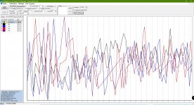
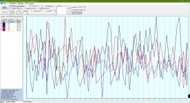
In the spirit of jumping into this, here is a typical RT60 plot taken from a REW measurement in my listening room (approximately at the listening position):

Chris A's listening room RT60 plot.jpg

I consider my listening room to be just a little bit "live" vs. what you would experience in a typical home theater room, but much less live than many lofts and hard surfaced dens and living rooms without any treatments. The room volume is 152 m^3 (5500 ft^3).

Chris

Singled Ended Ultralinear KT88

Hi All,

I am interested to hear about any user experiences or advice regarding output transformer impedance and B+ combinations for KT88 singled ended ultralinear operation.

My current amp is running EL34's with a 5k transformer right on the limit, with 412V across the tube and 60mA bias. I am very happy with the performance.

For the next amp I was contemplating running KT88's with a 5k transformer, about 400V across the tube and 100mA. However, looking at the KT88 datasheet it seems this tube might be most comfortable with 2.5 to 3k and 250V-300V across the tube.

I'm intending to run local cathode feedback on the output stage.

Interested to hear what you're all running.

Also can someone please explain the significance of the dashed lines on the curves below? I take it 425V is the highest voltage I can run across the tube and ther other one is presumably showing the grid 2 dissipation limit under some conditions I don't fully understand.

Many thanks,

Greg

1644920284282.png
Projects by fanatics, for fanatics
Get answers and advice for everyone wanting to learn the art of audio.
Join the Community
507,798
Members
7,888,848
Messages

Filter

Forum Statistics

Threads
406,261
Messages
7,888,848
Members
507,798
Latest member
Mrookster