The magic crossover - How to reach below 17Hz at -3dB with ultra-low phase distortion

2 x 18NLW9400, 152 liters each closed box (or both in one box of 304 liters) - processing see MathCAD screenshot, next post.
2 x 15MI100, 91 liters each closed box, processing see MathCAD.

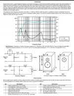
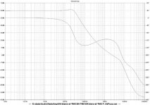
NO ANY resonator, filter corner frequency, steep phase decay, helmholtz, etc. between 20Hz and 400Hz -> Transient response at its best - tight controlled bass, group delay minimized. No Booming, no thunder, just pure signal. Absolutely perfect for home theater.
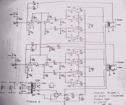
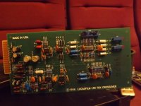
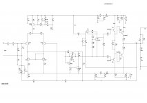
Crossover is done by pure mathematical magic :wiz: - see MathCAD.
Sensible Excursion distribution of both 15"s vs. both 18"s. So the 15s can go up to 400Hz without bad excursion caused intermodulation.
18s and 15s acoustically 100% in phase where it is most needed.
System level up to 108.75dBSPL undistorted, -3dB at 16.8Hz. (-10dB at 10Hz).
Aiming for below 17Hz may be BEYOND INSANE for music listening, but barely enough for some HT enthusiasts, over at avsforum.com. I am always wondering what kind of investment some guys there are doing to reach below 10Hz at medium SPL. This system is very cheap and light weight (at least in comparison to some avsforum freak systems).
Depending on the Amping used, the system may be below 170kg. Adding decent midrange and compression tweeter, DSP and amping, the whole system may be ~ EUR 6000 for DIY.
Next post is the MathCAD.

Quick question: Using X/Y rated caps in a normal position.

Hello all, I’m on a small tube preamp that I have. I’m removing all of the paper/wax caps and placing films. One of the values in the circuit is 2200pF or .0022uF. I have a roughly 250 .0022uF X/Y rated caps on hand so I’d like to use them as I have a lifetime supply lol. Would an X/Y rated cap function as a non safety cap in that location? It has nothing to do with the AC line, it actually connects to the volume pot. Just want to make sure it’ll work correctly.
image.jpg


Thank you,

Faulty Sony TA-S7 integrated - try to repair or turn into "Franken-buffer" preamp?

Hi Everyone,

I'm not sure whether this is really "Pass Labs" enough to post in this forum, but here goes anyway.

Tombo56 has a thread about his awesome input buffer (https://www.diyaudio.com/community/...ludef-sissysit-and-similar-amplifiers.382345/) and as I posted there I've made a pair and am trying them out in a (very) temporary chassis. I like them a lot, and need to fix them up in a more permanent home. A friend was throwing out his old Sony TA-S7 integrated amp, which he recently replaced because it is giving trouble (outputs cut in and out, volume sometimes suddenly jumps to full in one channel... maybe other things too...) and I rescued it from going to recycling. Initially I thought I'd have a go at fixing it (although I don't think I'd actually use it if it was working) and then thought alternatively I could maybe salvage some parts from it, and perhaps use the chassis as a home for the buffer pre.

Opening it up I found that there is a toroidal transformer, with a nice housing. It looks like the main output is +/- 18 Vac, although I'm not 100% certain I've measured the only secondary winding, since some parts of the power supply section aren't very visiv=ble, and I haven't taken it apart yet. Fiddling around a bit I found that all the remote control functioning works just fine (with a universal remote) with some of the audio circuitry disconnected, and apparently the relays switching the inputs work just fine with the pushbuttons (although so far I can't get them to work on the remote). This led me to wonder whether I could take out the power amp section and most of the preamp section, and simply build tombo's buffer into the case, using the PSU, relay outputs and remote control functions. This would create a sort of "Franken-buffer" preamp, with remote control functionality, and the really low THD and nice sound. (Physically a fair bit bigger than really necessary, of course.) The PSU would probably need a voltage drop (since I built the buffers for _/0 15V, but that's no big deal, and there would be plenty of space in the chassis to do it.

I've posted a couple of photos of the Sony below. One or two small boards have been removed for visibility.

So is it a shame to sacrifice an amp that could maybe be repaired? It seems it was well-regarded when new, but I doubt it's worth any great amount of $$ now, even fixed. Anyone have thoughts on whether the Franken-project is a good idea?

Best

Nigel

Attachments

  • PXL_20220403_165746134.jpg
    PXL_20220403_165746134.jpg
    569.6 KB · Views: 1,113
  • PXL_20220403_165801695.jpg
    PXL_20220403_165801695.jpg
    493.5 KB · Views: 835

Efficient 10VDC 5A filament supply 211 845 814 813

This is a little project of mine, based on some modules i made for someone i know who had noise issues with AC heating in his 813PP amplifier.

The original design specifications called for a module that was capable of making 10VDC 5A out of 10VAC with optional soft start and very low noise.

The modules use the off the shelf "Saligny" rectifier boards. https://evotronix.eu/main/

I have redesigned the original design to exclude SMD components.

The controller is a MIC5156YM and the FET is a IXTH80N075L2 for absolute reliability.

I will be posting gerbers in this thread once im finished with the redesign.

Attachments

  • modules in testing.jpg
    modules in testing.jpg
    248.1 KB · Views: 236
  • modules in use.jpg
    modules in use.jpg
    285.1 KB · Views: 234
  • modules close up.jpg
    modules close up.jpg
    234.6 KB · Views: 222
  • amplifier image.jpg
    amplifier image.jpg
    147.6 KB · Views: 229

Please clarify how non full range speakers can get damaged with low frequency?

Hi,

When you listen to typical 2 channel setup, regardless speakers size, be it towers or small bookshelf speakers, the low end could be 20Hz-80Hz.

If the smaller speaker cannot play anything lower than 80Hz by design, how would it get damaged?

Or does this only apply to home theater system where you set speakers to Large for full range but speakers can only gown down to 80Hz?

I thought anything below the 80Hz, the speakers just cannot play it due to the crossover cutting off those lower end frequencies?

K-16LS Problems

I recently purchased a K-16LS Tube Amp Kit from TubeDepot. Put it together; pretty easy kit to built, and sounded really amazing. However, it was just sitting out on the circuit board, so today I decided to put it in an actual case, and somewhere along the way, I ruined something. I'm new to building anything like this, so excuse my naiveté if I ask/did something stupid here.

What I changed:
I mounted everything to an aluminum chassis. I used that to ground everything, with the power supplies mounted straight on top.
I see that this setup, the negative terminal on the speaker is just the ground, not a return signal, so the negative speaker terminals I just mounted right to the chassis as well.
I wanted to put two different inputs, so I added a DPTS, attaching the audio inputs from the RCA cables to that, and then just grounded all the sheithing together (again right to the chassis).
I needed to add extra length to a lot of the wires, so there's plenty of opportunities for error here (or at least unforseen shorts).

Problem now:
Almost no sound from the speakers (sounds very very faint -- like its either not, or barely being amplified form the line level)
High pitched squeal from the amp
Somehow, and this one I can't explain at all, I hear music faintly from the amp itself.

I've checked a bunch of the voltages:
getting 13ish V from pin 2 on all the 7 pin tubes
Getting mid 200's V from the 220uF and 110uF capacitors

Any suggestions? Where should I look next?

Attachments

  • k-16ls - schematic.jpeg
    k-16ls - schematic.jpeg
    89.3 KB · Views: 179

Troubleshooting Gallien Krueger 800rb Bass Amp

Hi all,

I have a GK800rb (schematic/service manual here, preamp board rev E, power amp and power supply board are rev C) which has obviously seen heavy use. It is currently damaged on the 300w side and I'm having trouble pinpointing the exact problem.

Symptoms:
- DBT (75w bulb, no load attached) glows as I turn up the mains with a variac
- DBT does NOT glow if I disconnect the +/- 85VDC wires from the power supply board (all power supply rails are correct)
- DBT also does not glow if I have the +/- 85VDC wires from the PS board connected and I disconnect the +/- 15VDC P2 header from the power amp board

What I've tried:
- Replaced the obviously burnt components on the power supply and power amp board (most of the output transistors and some of the A06/A56s, a few resistors)
- Rechecked the output transistors for shorts/opens

I would like to probe voltages on the 300W section, but I don't want to leave the amp powered up with a bright bulb. My next thought was to replace U1 (even though the 100W side of U1 seems to be ok). Is there a way to check this JFET in circuit? Any other tests I can do without powering up the 300W side?

Thanks for any and all help!

Design speakers for my expedition vehicle?

I'm building an expedition vehicle, which is basically a tiny house on the back of a huge 6x6 lorry (see below for photos).

I'm having the habitation box built professionally but it's going to be empty, so I'm fabricating all the cabinets and furniture myself from birch ply cut on a CNC machine.

I have spaces reserved for speakers at the end of the kitchen cabinets, directly facing the bed / seating area. The spaces are 500mm high, 400mm wide and 150mm deep. My plan was to install off the shelf "in wall" speakers (perhaps B&W CWM663) into these spaces, but I'm acutely aware that the sound could be greatly enhanced by properly designing an enclosure to fit the space (a port could could go on the bottom or side of the space).

However, I'm totally overwhelmed with a million other custom jobs on this project, and learning yet another skillset isn't something I have time for 😂

Would anyone like to help me out by designing the enclosures, picking most suitable drivers and advising on crossovers etc? Alternatively if there's an off-the-shelf solution that would neatly fit this space, that would be amazing...

Here's the truck:

IMG_5807.JPG


This is what I'm hoping it'll look like when finished:

render-1.png


Here's the interior with the speaker placement highlighted:

Screenshot 2022-03-28 at 09.24.56.png


Screenshot 2022-03-28 at 09.25.39.png
  • Like
Reactions: gazzamongo

NAD 7020 transformer

There was a similar question 13 years ago, which got no replies, so I'm going to tell my story, and hopefully someone will take pity on me and engage with me.

I was getting some miscellaneous hums and pops in my UK 240V NAD 7020N (single main board, power amp supply on the speaker connector sub assembly), so I recapped most of the larger electrolytic caps, but during the process, I put C901 (1000uF, 35V) in backwards (I know, stupid). When it powered up, it blew one of D901 or D902 (not surprisingly). I did not have any BAV19s to hand, so I just grabbed a couple of matching diodes with apparently similar values, replaced C901 (again) and both diodes, and was very relieved to find the receiver powered up OK.

All was well for a couple of months (and was sounding good), but suddenly it started just humming on both channels rather than playing music.

When I opened it up again, and powered it on, it was clear that R901 (10R 1/2W) was burning. As this is the same part of the power system as the previous fix, I took out D901 and D902, and found one had failed shorted, and was feeding AC to the tuner.

As I had actually bought some BAV19s, I replaced D901, D902, and C901 again, and also R901.

This made the receiver work again, but I thought I'd put it on the bench for a while and soak test it while it was out.

After a couple of hours, a faint mains hum started, which proceeded to get louder and louder, and the volume dropped. Shortly after that, a sweet, rather sickly smell started to come from the transformer, and on feeling the transformer, it was quite hot (around 50C when I used a thermometer).

I checked all of the components I had changed again, but everything still seemed good.

I guess that the lacquer on the transformer or the coils was breaking down, and that something was shorting in the transformer. When I measured the AC voltages (after removing the DC fuses), I found that the AC to the power amp was only showing 22.1V AC on both halves compared to the centre tap (supposed to be +-29V DC after rectification and smoothing, and the AC to the pre- and feeded amp was showing 17 and 14V (suppose to be +29.13 and -23 after rectification and smoothing). The AC voltage to D901 and D902 is only 7.2V.

I believe the windings should be 35-0-35 and maybe 30-0-30, but I don't know what the supply to the receiver part should be. I guess from the value of the zener D903 (15V) that it should be 18-20V after rectification.

The service guide is no real help.

Something is screwy in the transformer (I always knew it was failing, because there was a faint mechanical hum for some time before the failure), but there are no 2nd hand parts around at the moment (not that old ones are likely to be much better). I was considering putting a toroidal in for the power amp, and doing something else for the other parts of the supply, but not having definitive values for the different circuits, I am unsure of what I can do.

What I really need is someone to confirm the AC voltages and power ratings on the transformer, so over to you, whoever reads this thread.

QUAD 33 filter problem

I'm seeing some troubles with the filters on my Quad 33 pre amp. The fault is that when 5K or 7K is engaged, and then using slope the right channels cut's out almost immediately. It comes back when slope is set at 0. It works flawlessly on 10K. Is this probably a problem with the switches or something else? I've tried cleaning them, but from what I can tell it seems hard to get inside of them. Anyone has had this problem themselves or has an idea where to look next?

Open circuit on 2 way crossover, troubleshoot help please.

Hi,

I have the tiny polk blackstone satellite speaker. It measures open at the speaker terminals instead of 4-5ohms.
I scraped the pcb and resoldered each joint. If I do continuity from point to point, it makes connection except at the speaker terminals.
Both the tweeter and the woofer are good.

There are 3 caps, 3.3uf, 18uf, 300uf. If faulty, would it show open at the speaker terminals(amp side)?

Probably take you few seconds to figure it out. 🙂
70B62625-81CF-4122-BAD4-32EB5BA7CD19.jpeg

Attachments

  • 21539344-5653-435D-A89F-78647E2DD1CC.jpeg
    21539344-5653-435D-A89F-78647E2DD1CC.jpeg
    457.3 KB · Views: 132

Today, my radio went up in smoke

Argh!
We havea situation here: the electric installation in our flat goes somewhat crazy. It began with flickering lamps. Then, while switched on, they‘d begin to go dark in circles (one room after the other), or dimly light at a fraction of its usual brightness, and then turn much brighter for a short time.
Then my table-radio (a nice sony cmt-x5cd) literally went up in smoke!
Sad and frightening this is.

Attachments

  • 1A3B195B-3313-4E26-9A9A-1483B0FE4A5E.jpeg
    1A3B195B-3313-4E26-9A9A-1483B0FE4A5E.jpeg
    61.5 KB · Views: 186

UK source for budget audio kits?

Anyone know of a UK-based operation that is comparable to Parts Express or Meniscus?

I'm specifically wanting order a budget speaker kit like the Overnight Sensation or C Note, to a friend's daughter as a present. She's an early teenager, and clever enough to figure it out (well, he might have to oversee the soldering).

I can't find anything similar though, the closes thing is an EU based store that has the Overnight Sensation for twice the cost, and there's probably some shipping complexity post-Brexit on top of that as well.

Usher 8948A woofer 9930 tweeter bookshelf speakers - LOCAL PICK-UP - Nashua, NH

Usher 2-way bookshelf speakers
Partsexpress kit/design based on Usher 8945A and 9930 drivers.
These are very high end, low distortion drivers and in the league of ScanSpeak to which they often compared with.

Bought these from Joe D’Appolito himself; he said they can be used with 8948A and/or 9950 tweeter.

One grill has 1cm hole in it and one 9930 tweeter has gouge in faceplate; both are from B&C pro woofer hitting it, otherwise speakers are perfect. Wrapped in towels, nothing ever touches them.

I actually put 9950 tweeter in one of the speakers and I can't tell the difference between 9950 and 9930 after years of listening to them. I have the old 9930, it's fine.

The 8948A is more of a midrange woofer and 8945A is mostly a mid-bass woofer really. With 9930 and 8945 you really stretching the lower and upper limits of those drivers, IMHO.

$450 or best offer.

Attachments

  • usher-manual.JPG
    usher-manual.JPG
    254.2 KB · Views: 494

For Sale Naim Audio 42 with Avondale upgrades and Avondale TPR4 power supply.

For disposal:- A superb sounding Naim NAC 42 with many Avondale Audio upgrades

Noble stepped vol pot.
High quality input selector switch.
Capacitors, resistors etc upgraded in critical locations to the gain stage along with Avondale Gyrators.
High quality audio grade wire through out.
Phono (RCA) output added, existing Naim 4 pin retained (don't use both at the same time)

There is an matching Avondale Audio TPR4 power supply in a re-purposed Naim case (not sure what is was originally) but looks good with the 42. ? The TPR4 is from 2020 and I've fitted a new KEMET smoothing capacitor (2021) and checked the 24vDC supplies from the TPR4's.
Comes with a 5 pin to 5pin PSU cable (not an interconnect) and only the top socket to be used, the lower one has nothing connected at present and is there if some one in the future wanted to add a second TPR4 so this unit would run two devices.

The cases could do with a good clean.

51977302261_38ed0669ea_b_d.jpg


51977302296_d382438b53_b_d.jpg


51977302381_2986af87a1_h_d.jpg


51977583239_897eaf07a2_h_d.jpg


51977302421_dcfec3f8ea_k_d.jpg


51977379933_a88bbb7926_k_d.jpg


51977379973_482615d2e2_k_d.jpg


51977865835_f73ddc9a1e_b_d.jpg


51977583384_6239ae92ff_k_d.jpg


51977380043_c1026ab07d_k_d.jpg


This combination of Avondaled 42 and the TPR4 PSU sounds superb.

Any audition welcomed (Hampshire UK) by arrangement.

£600 the pair + shipping at cost to the mainland UK only or collection in person.

FS: Blank MOFO pcb boards

I have several sets of MOFO boards for sale. 1 original pair and 2 pairs of Prasi’s design. All are excellent, and untouched. Original design by the very generous Michael Rothacher.

Original MOFO board pair: $OLD!
Prasi’s MOFO board pair: ALL SOLD!

PayPal preferred.

Best,
Anand.

Attachments

  • 9E541EEE-85A3-4851-AB06-24BC8DF34DBE.jpeg
    9E541EEE-85A3-4851-AB06-24BC8DF34DBE.jpeg
    560.7 KB · Views: 465
  • 4BA64EF6-6C3D-488F-AA46-8C66669E4625.jpeg
    4BA64EF6-6C3D-488F-AA46-8C66669E4625.jpeg
    261 KB · Views: 456
  • EE58D091-D225-4980-B859-BD127FF67C2F.jpeg
    EE58D091-D225-4980-B859-BD127FF67C2F.jpeg
    609.1 KB · Views: 446
  • 722996AB-2281-4E8F-AC3B-C4001996C0C5.jpeg
    722996AB-2281-4E8F-AC3B-C4001996C0C5.jpeg
    63.3 KB · Views: 423

Lucasfilm Ltd THX Sound System 3417 crossover monitor

I've had the Lucasfilm Ltd THX Sound System - 3417 crossover/monitor in my home or home THX cinema now for some years.

Behringer DSP DCX2496 are used x4.

There are two 3417 that I own and DSP D1138 that is a bit complex to set up as it needs remote software that I have in a file but runs on the windows XP that I still have about.

I simply like the Lucasfilm Ltd THX Sound System.

THX sound system is seen briefly in the video where I have installed extra height channels x12.
YouTube

Attachments

  • 81926973_10157734886300149_799698566640566272_n (1).jpg
    81926973_10157734886300149_799698566640566272_n (1).jpg
    74.7 KB · Views: 627
  • 78177242_10157651371910149_454583259913781248_o.jpg
    78177242_10157651371910149_454583259913781248_o.jpg
    56 KB · Views: 424
  • 81432206_10157734885960149_2775009255055425536_n.jpg
    81432206_10157734885960149_2775009255055425536_n.jpg
    112.6 KB · Views: 495
  • 81475368_10157725320010149_9138818969908543488_o.jpg
    81475368_10157725320010149_9138818969908543488_o.jpg
    96 KB · Views: 448
  • 81358603_10157734886130149_7400512234813652992_n.jpg
    81358603_10157734886130149_7400512234813652992_n.jpg
    127.1 KB · Views: 658
  • 81624687_10157735024275149_5405506892258607104_n.jpg
    81624687_10157735024275149_5405506892258607104_n.jpg
    89.8 KB · Views: 338
  • 81389191_10157735324915149_9027216186047201280_n.jpg
    81389191_10157735324915149_9027216186047201280_n.jpg
    145.3 KB · Views: 470
  • 59688383_10157049516285149_7153098161236475904_n.jpg
    59688383_10157049516285149_7153098161236475904_n.jpg
    59.9 KB · Views: 366

bootstrapsCCS+T-TMC

This is simple amplifier with bootstraped CCS for the VAS. It uses deplation mode DMOS FET from Supertex for CCS.
There is TMC bridged with resistor//capacitor. OLG is 60dB up to 30kHz.
I started it from DX-blame+TMC showed in other tread. If anybody is interested I'll give more information next. The schematic and OLG diagrasm are here.
I am not good at explaining the sound but this one is really good and I built a few , some with ordinary Miller comp. and JLH 80W I modified and showed.
dado

Attachments

  • DADO-TMC-T_bootCCS.jpg
    DADO-TMC-T_bootCCS.jpg
    233.2 KB · Views: 3,032
  • DADO-TMC-T_bootCCS_OLG.jpg
    DADO-TMC-T_bootCCS_OLG.jpg
    48.8 KB · Views: 2,853
  • amp-board.jpg
    amp-board.jpg
    45.6 KB · Views: 2,614

For Sale Ethernet to fiber converter

Hello all,

selling a set of ethernet to fiber media converters
4 pcs- tp-link sm311lm sfp module
2 pcs- tp-link mc220L media Converter
2 pcs- trendnet Tfc-1000mga/a media converter
1 pc. - Om1 LC to LC fiber cable (7 inches)
1 pc - Om1 LC to LC fiber cable (8 meters)

asking $150.00 for the set or send me an offer.. buyer pays for paypal fees and shipping fees.

thanks

Attachments

  • 9F09E456-A730-4C4C-842A-8CADC752B0B0.jpeg
    9F09E456-A730-4C4C-842A-8CADC752B0B0.jpeg
    987.7 KB · Views: 153
  • 8DA7C7C6-59EF-413F-9DDB-68879C45ADE6.jpeg
    8DA7C7C6-59EF-413F-9DDB-68879C45ADE6.jpeg
    1 MB · Views: 102
  • 483ACBC9-8DDF-49BD-AF64-F0B80640C5A0.jpeg
    483ACBC9-8DDF-49BD-AF64-F0B80640C5A0.jpeg
    772.9 KB · Views: 107
  • 2BD60425-F167-46E7-B19D-F194DF2563D1.jpeg
    2BD60425-F167-46E7-B19D-F194DF2563D1.jpeg
    996.4 KB · Views: 113
  • 670F7125-FF67-440A-97FD-04D6C2822B69.jpeg
    670F7125-FF67-440A-97FD-04D6C2822B69.jpeg
    516.4 KB · Views: 105
  • 27F560DC-E71B-494A-8CAB-97ADB990162D.jpeg
    27F560DC-E71B-494A-8CAB-97ADB990162D.jpeg
    822.7 KB · Views: 148

Diy dac output stereo problems

Hello all,

Just finished a ess9028 dac. It has been a long project..been stalled for a year and not really finished 🙂
But enough to play with it.
A strange problem with the output.
if i put one rca from Dac all is fine, doesn’t matter if it’s left or right channel. Both play fine. So stereo output from Dac seems ok.
But when i connect both left and right at the same time left channel dies But right play.

any idé?

br// Daniel

I Have Finished My Standel 25L15 Clone

I have attached two pictures of the Standel 25L15 clone. It took a lot of digging on the internet and in books to come up with the schematic. I built this project because I had an original JBL D130 from the late 50s early 60s and I love Chet Atkins guitar playing. Chet used one of these amps for every one of his recordings from the late 50s until he died.

The amp uses two 12AX7s in the preamp, a 12AU7 driver, two 807s for the outputs and a GZ34 rectifier. It puts out right around 24 -25 wattts Class A push pull.

I have a Gretsch Chet Atkins Country Gentleman which I play through it and the sound is fantastic.

Attachments

  • 25l15 back_resize.jpg
    25l15 back_resize.jpg
    87.4 KB · Views: 2,842

Audio Technica MC cartridges

Hi, I have the following practically new cartridges for sale. Prefer US sale and will ship flat rate box. Other shipping for additional charge

Audio-Technica AT-OC9XEN -- $200
Bought as backup cartridge and mounted to headshell and played 1 album (headshell not included)

Audio-Technica AT33MONO -- $150
Mounted to headshell and played 5-6 albums (headshell not included)

Thanks

LU1014D Pass stash contest

**** ANNOUNCING ****

A contest. There two prizes. A first place prize and another first place prize. The idea of the contest was approved by Mr. Pass before I made this post.

Each prize is a matched quad of LU1014D from the Pass stash. There are exactly two of these quads in my hands from the 500 piece stash that I matched.

The rules are simple. You design a SUSY LU1014D amplifier and post a working LT SPICE model of the amp you designed including all files to run the sim. If you do not know what SUSY is, if you are not versed in LT SPICE, you have to go figure it out. Hopefully your design will be one to three stages max just like the Firstwatt and Pass Labs amps that are discussed and cloned (with the blessing of Mr. Pass) on this forum.

I will likely confer with one or more DIY members to pick the winners. If there are more than two great submissions, I may award matched quads from my personal stash at my discretion. The picking of the winners could be totally capricious which would make the contest more of a lottery and not the first lottery of Pass stash parts.

Ground rules. No arguing or complaining. Just submit your design and be patient. This contest is intended to generate interest and discussion and bring out some new designs of the LU1014D. There are lots of these parts in the surplus market. I have purchased hundreds of them and they are genuine triode curve parts.

The contest will be open for one calendar month ending July 12th.

Let the submissions begin.
  • Like
Reactions: myfirstamplifier

Qcc3034 Programming

Hi Guys,

I have been working on a project that involves using an esp32 to create a portable bluetooth speaker that can be connected to a custom BLE connected app to control addressable led strips over a single bluetooth connection. Whist I have had a lot of success doing this, I would love to be able to wirelessly connect multiple speakers together to play synced audio.

After some research, it seems as if the esp32 isnt capable of doing this 🙁

Qualcomms Broadcast audio technology seems like the perfect solution to my problem, however, It means restarting my project on a Qualcomm chip.

My question is, can a Qualcomm qcc30xx series chip be programmed in a similar way to an esp32/arduino to be able to send/receive serial data? Even if it means being able to receive serial data and then pass it onto an esp32 to control the led strips?

I really dont want to have to have 2 separate bluetooth connections/names showing up on the users phone(one for audio on the Qualcomm chip and one for serial on the esp32) as it would ruin the user experience.

I have seen a lot online about reprogramming them to have custom names and creating dsp profiles but thats about it.

Any guidance on this situation would be greatly appreciated!

Mesa Boogie 395 power amp reverse engineering

Hey guys!
Long time no see.. 🙂 Happy New year!

After several years of having this amp I finally pulled it out the rack, cause it suddenly became silent. Short tests showed that was a 5v rail related issue and the problem was simply a 1n4007 diode, that rectifiers 6.3 VAC for 7805 regulator. Without 5 volts input LDRs are open, thus no signal goes thru. After replacing it, the amp came back to life! But I thought it would be great to reverse-engineer this puppy, cause I still can't find its schematic whatsoever.. So, what the heck?! 🙂
And after 3 full days and 4 evenings I've finally done drawing. Here it is:


https://drive.google.com/file/d/1bzIvRelnxfL81XCXtqnjrrWVkSMnSQSL/

There are:
1) Different photos of the amp's guts.
2) PCB file, drawn in Sprint layout 6.0.
3) DWG file with schematic.
4) PDF file with schematic.

Also I'm attaching the circuit diagram directly here for the easy of reference.

Later I'll measure all voltages and include em onto schematic as well

If you find something obvious - please let me know.

PS. Lemme tell ya, this amp is a mess... As any Boogie amp - getting PCB out is a HUGE pain in the a... neck - desoldering is mandatory - I guess connectors are not a solution for Mesa.. LOL
One thing, that caught my eye, is channel A shielded cable is tided up together with AC mains input line.. Hmm.. is it strange? Also no AC wires are twisted at all. Of course, there is no instrument level signals, but why, Mesa?

PS.PS. I've been still figuring out the ac mains portion of the pcb layout - so take it with a grain of salt.

Cheers, Phil.

Attachments

  • Like
Reactions: JMFahey

Cheap Red LED bias on ecc83/12ax7

Dear All

I have used LED cathode bias on a number of valves, but only recently tried it on some ecc83. I am pleasantly surprised with the improvement.

The problem with LED bias on ecc83 is that the current draw of this valve is too meager to induce any standard LED to conduct. I therefore bring the LED to continuously conduct by an additional connection, bypassing the valve (and annode resistor) entirely with a separate sufficient wattage higher value resistor directly to the HT.

The value of this resistor is chosen to drop almost all the HT and deliver approx. 6mA current to the cheap red LED. For my test circuit I am using HT of 280 Volts so chose a 5 watt 47K ohm resistor that I had handy. I pre-selected the red LED's and chose two that elevate the cathode by 1.67 volts on each channel.

My method of testing for linearity is a crude point-based method. Nevertheless, I measure distinct improvments that I believe can be heard with my own ears...

The by-passed LED bias on e83cc also seems to remove any last vestiges of power supply noise. Perhaps there is a bit of aikido-stype ps noise injection in this method. Since I by-pass the LED to make it continuously conduct, the effect is electrically similar to filament bias.

When I have used LED bias on other valves the change is distinct and subtle, but the changes I am getting with this method on e83cc seem even more significant. Maybe it is just my own biased hearing though. Has anyone else done this before?

Ian

Attachments

  • IMG_1476.jpg
    IMG_1476.jpg
    115.8 KB · Views: 2,836

Tube heater voltage regulator

I have a (probally noob) question, and the search did not give me an answer...

Many use voltage regulators like the LM317 for their regulated dc heaters in tube amps/preamps. But that require a whole circuit arround it. Why do you not use a fixed voltage regulator at 6.3v like the NJR NJM2396F63 for this? It makes the circuit much more simpler. Or is there a good reason that i do not know yet?

Thanks for your arguments pro and contra.

Tube regulator goes over target voltage then settles

Hello. I am learning about series pass regulators. I have breadboarded the following regulator, which works fine but at startup the output voltage climbs well past output target of 270V - goes all the way to 365V (ie. the input voltage) before settling down. Can someone suggest how i can correct this? I just want it to climb to 270V and stay there.

Screen Shot 2022-03-06 at 9.18.27 AM.png

New TU-8600S Delivers as Promised

I finished building the TU-8600 with full upgrades and Cossor tubes a few days ago. I'm at about 30 hours time on it now and it has smoothed out considerably from the first day. it sounds absolutely wonderful. I'll spare you the long list of adjectives; see Herb Reichert's review, yea, that's how it sounds.

The process wasn't without a couple of hiccups. I used too much heat on the connector pins and they moved, so I couldn't connect the transformers until I got that straightened out. If it had only been one or two I could've probably moved them back into alignment, but I decided I needed to replace them and Victor FedEx'd me a new set. Then, I thought I was ready and flipped the switch but nothing happened. Victor said it had to be either parts out of place, backwards, or a bad solder. I had already checked everything carefully, and continuity was good in the circuits, but I checked and rechecked a few more times and couldn't find it. So I decided to take it to an electronics guy to have him to check my work and troubleshoot the issue. It turned out that the power switch wasn't making contact (which I suspected, but didn't have the confidence call it), and he was able to repair it. The voltages checked out. Done. I was relieved (to say the least). With the benefit of practice and experience, it would be fun to build another.

My reference was the Bottlehead Stereomour 2A3 I built several years ago, and have thoroughly enjoyed. This 300B is quite different despite also being a SET amp. This is just a different category, probably my end game amplifier. I have some of the most sensitive speakers ever made, and this amp is dead silent with the volume well above listening levels. Clarity, space, tone, detail, tight bass, soundstage... piano being one of the more difficult instruments to reproduce well, for me it's really satisfying hear realistic richness-depth-nuance-power in solo piano. Martha Argerich's Legendary 1965 Recording... Oh my goodness! And the Bach Toccata and Fugue in D minor BVW 565 recorded by Peter Hurford on the Rieger organ in the Ratzsburg Cathedral - I hope the neighbors appreciate it as much as I do!

@Victor, thank you for all the great support!

Choosing best output coupling capacitors for B1

I've just returned to a PASStime that I really enjoyed a few years back. But i never was an electronic genius, not even qualified as a novice, just an interested party. There just seems to be something different about listening to music from circuits self crafted. Anyway, i have an unfinished balanced B1 project and a stash of 13µf 250v Axon caps I was thinking of using in place of the 10µf values originally called for. I would appreciate comments, calculations for effect on frequency response or such. Deeper in the stash is a set of 6µf 140v caps. Are there any mathematical rules of thumb for choice?
Thank You,
Charles

p.s., inside my old stash bag is a pair or two of Aleph-X Rev 1.0 boards received from Chad Simpson long ago. Any comment on their project viability or desire by another diyer?

  • Locked
New members can not send Private Messages (a.k.a. Conversations)

New members who are still under moderation are not allowed to send private messages. Also known as "Start a conversation."
This is to prevent spam by private message.

If you need to contact a forum member about a group buy, or an item on offer, you can post in the thread to request a PM. You will be able to read an reply to that PM.

Once a member has cleared moderation, starting PM will be available.

Shishido/Loftin-White 2A3/45 Extasy..

Hi guys.

I rarely send posts, but I thought I would share this small project since it brought me so much fun, and musical enjoyment.

I know that tiny SE-Triode amps are not favored by the majority, but for those of you who happen to own (and apreciate) reasonably efficient speakers, this amp is lively, 3D and a real pleasure to live with.

I'm not knowledgeable alot about technology, but I'm learning.. So far, I've built a fairly nice 300B SE amp, a couple of 2A3 amps, and a Gainclone. All successful, and in no way, do I miss my previous Audionote 300B, neither my Audio Research (D70 yuk) or CJ.

This amp is the Shishido (loffin-white) 2A3.

Link: http://www3.sympatico.ca/wenchieh/2A3_schematics/shishido.jpg

It's easy to build. Almost no parts. I had build it with huge Hamonds 1627SE Output trannies, but lately I ordered 125FSE trannies, so I can substitute output tubes for 45 and WOW. Ok, it can play almost loud enough for most stuff. (with my Tannoys, and with Castle Chester) not very LOUD, but very adequate for every day use.

My 300B is the best "compromise", followed by the 2A3, but I must admit that with the 45s, everything lock in place, 3D image, timber naturalness, focus. A feeling of being there, especially on guitars, and on piano too. In fact, I love so much this amp, I might dig out my big 15" to see how it matches.

Well, this is it. I'm just excited at the idea of listening more and more music with it. A nice find, and by the way, these little Hammond FSE125 are real gems for a cheap price.

Help with *RARE* Vintage Mixer

Hello to everyone! Newbie here! Hope you're doing great!

Decided to finally pull out from the shed my old analog mixing desk , it's an italian FBT 18SR from the 70's , 18 channels , I'm planning to use it for my drum kit , but before that, I want to test all channels real quick.


Being a very old mixer , it only has TRS jacks (mono) ,to test it, I was thinking to hook up an SM57 to channel 1's input , insert a mono TRS cable into one of the outputs (Either Mon 1/2 or L/R outputs and connect it to a guitar amp (in this case a VOX AV60 , or a couple of speakers (w/preamp) that use RCA jacks. Not getting any results , (because I have no idea what I'm doing) , so I ask you kind experts: what are the different ways to hook up this mixer to test it? Just to get a sound.. , I'm sure I'm making ridicolous mistakes!
Apart from trashing this old lady , I'm willing to hear your opinions!
RR/RS

Attachments

  • 01.jpg
    01.jpg
    415 KB · Views: 221
  • 02.jpg
    02.jpg
    265.5 KB · Views: 212
  • 03.jpg
    03.jpg
    220.9 KB · Views: 186
  • 20220401_120517.jpg
    20220401_120517.jpg
    246.1 KB · Views: 210

Audiolab 8000S and 8000A PA resistors getting hot

Hi

I have an Audiolab 1997 8000S and 1986 8000A, both of which are working fine.

However, the 8000S resistors 721, 722, (724, 725, 821, 822, 824 and 825) are visibly burnt. They seem to be 4 sets of parallel configured resistors to give higher power ratings. They have been obviously getting hot for a while as the circuit board is discoloured. My schematics are dated 2005 so are for the Chinese version amp. The diagram says these resistors should be 3K0. which in parallel, will be 1K5. Actually, with my amp built in 1997, they are 2K0, so have a total R of 1K0.

The 8000A circuit is similar but not identical. It has 3 x 4K7 resistors in parallel
(R447, 449 and 451 according to my circuit) to give 1k56, which is similar to the Chinese version of 8000S.

Using a DVM, there is upto 32V dropped across the resistors in the 8000S, giving a power requirement of about 1Watt which might explain why they are burning.

Although I have made measurements etc, Im no Designer.
So what do these resistors actually do?
Will changing them to 3K0 on the 8000S be a good idea, so as to reduce the current and therfore lower the wattage needed?
What effect will this have on the sound of the amp, if any?

Moskido Hybrid Aikido-MOSFET Amplifier

If I had to restart my hifi hobby and could keep only one component that I own now - it would be my DIY Moskido amps which sound better than any amplifier I have ever heard. I completed my Moskido amps about the time the Moskido thread disappeared from DiyAudio which may have left a few persons stranded in the middle of their Moskido projects. The purpose of this thread is for the DiyAudio community to help each other complete their Moskido amps.

For those of you who are new to the Moskido amp design – building one of these is for the advanced audio DIYer. All the Schematics for the Moskido can be found on Bob Prangnell's excellent Mad Scientist Audio web site in the DIY section. The heart of the Moskido is the Aikido gain/driver stage. Aikido boards/kits can be purchased from Glass-Ware through the tubecad.com web site.

Bob Prangnell's schematics are for a 50 watt/channel class A amp using a 6SL7->6SN7 Aikido and a double pair of complementary MOSFET power transistors. I originally built a 10 watt/channel Moskido using a 6SN7->6BX7 Glass-Ware Aikido and a single pair of MOSFET power transistors. I recently designed a 7193->6BX7 push-pull Aikido PCB which is discussed in a separate thread (http://www.diyaudio.com/forums/anal...6bx7-push-pull-aikido-preamp.html#post4653656), but has a voltage gain of only 7.7x which works great with my 98db efficient speakers. Judging from the heat produced by my 10 watt Moskido, the 50 watt units must be serious room heaters.

Edit: The new Bias PCB has been working great for 2 years now. The Obligato Gold coupling caps sound amazing. Vocals have never sounded so natural on my Moskido amps! The Bias PCB eliminates the nasty project step of bread-boarding Bias boards from a schematic. I can also email the Eagle files to anyone who is interested in them, however, this PCB includes at least one device that I created in a lbr file. The BOM and instructions are complete. Because I am not allowed to change/add attachments, please go to last post for more information.

Attachments

  • Moskido front.JPG
    Moskido front.JPG
    369.2 KB · Views: 2,526
  • Moskido side.JPG
    Moskido side.JPG
    399 KB · Views: 2,393
  • 7193 pcb assembled.JPG
    7193 pcb assembled.JPG
    244.4 KB · Views: 2,378
  • 7193 bottom Moskido.JPG
    7193 bottom Moskido.JPG
    736.2 KB · Views: 2,449

RIP Sandy K aka Alex Kethel

Alex was a longtime member of DIY Audio. He passed away April 2nd. from complications of cancer surgery. He was a major contributor on Rock Grotto Forum.
Among his accomplishments were the improvements to the Jaycar desktop amplifier, great improvements to the JLH Ripple Reducer & making a stellar Headphone amplifier from a bog standard 15 watt unit to an extremely high quality unit that w2as considered sonically equal to a $33,000 preamp.
He will be sorely missed!

Lux91 Mono Max - Technical Help Required

I could use some technical help. I have some relatively new Lux91 Mono Blocks (arrived in March). The amps have been fantastic until yesterday when one channel cut-out. I checked the fuse and it had blown. I have since replaced the fuse a couple of times and it immediately blows when the switch is turned on. I removed all tubes and inserted a new fuse and it still blows every time I turn the amp on. I have visually inspected the internals and nothing looks to be out of the ordinary. Can anyone walk me through some quick checks /diagnostics to isolate the problem.

Any help would be greatly appreciated.

Thanks

How does digital audio even work? (Specs, protocols, error handling, clocks??)

I realize that I don’t have the foggiest idea how digital audio is transmitted, at the basic layers. How is it steamed from a device to a network steamer? How is it transferred to a DAC? What protocols are used, how is transmission failure or errors handled?

Feel free to link me to articles, I know I’m asking very broad questions. I don’t know where to jump in.

JBL 127H-3 and JBL 2412H

I got these in a plastic cinema speaker (JBL 8340A). Unfortunately (and as expected), the foam surrounds have disappeared. The 127H-3 looks like a speaker worth refoaming - anyone any experience with this model? And these could serve as party boxes that could be permanently installed in my second garage with their nice wall holders.

I wonder how critical is the foam/rubber to be used - will a generic one do if having correct dimensions?

Passive radiator for bass guitar?

Does anyone have any experience with using passive radiators for musical instruments? I was thinking of building a passive radiator box for my bass to keep the box small and get good lows from a 12" speaker.
The radiators I've seen are all foam surrounds and I'm thinking I'll be blowing the cones into the grill cloth 1st big notes I hit.
Why would I want to do this? I have a bassman with the crappy oxford 12" and I want to replace them with something that will give me good 40Hz response. The bassman box is very small, but it fits in my Camry, which is nice. Otherwise, I'll just replace the oxfords with a pair of eminence basslite 12s for about $160US.

6N1, 6N2, 6N11 (6DJ8) in pre?

I have tube pre kit which (supposedly) works with any of these. Which is most linear? Most musical? Or otherwise preffered?
I can get some or all, and compare, but even different supliers can result in different sound.
Any recommendation? They do have different heater current demands, so i have to account for this.
I already have one working in box and second is up and running on the floor. I want to replace all my solid state pre, as this pre has more musicality for me. I got no schematics, sorry.

How to get rid of old TAS, Stereophiles, etc...

I got boxes of old ( mid 80s to Y2K+) Stereophiles, TAS, TPV and SGTHT.

And after years of looking at those boxes taking space that could be use better, ie: MORE audio stuff, I figure it's time to get rid of that. I will never read them again. (*) so time to give them the heave ho.

But they are in very good shape. I doubt the library will take them and I've seen them sold on eBay, Craigslist. But it's a PITA because I got other things to do with my life.

It's doubtful The Salvation Army, et. al... will take them.

And, I'd hate to put them in the recycle.

Any ideas? I'm not in for the money, OK, if you give me a nice F5 Turbo V5 and a Marantz 4140, I might... ;-)


(*) Like everything else, I know once I get rid of them, then I'll want to read them. 😛

Vacuum Tubes from Russia

Hello--

Apologies if this post is not in the right place or is otherwise inappropriate.

My last order from an eBay seller I've used a few times was placed the night before Putin announced his invasion of Ukraine. The seller is a Russian gentleman who has always provided excellent prices, shipping, packing, communication, and so forth. His seller name was/is "12-ROCKETMAN".

I followed up after the order with how he was doing and he explained that he has moved his operation to Kazakhstan and is stressed out due to being blocked from selling on eBay. This morning, I received a message explaining that, as he does not have a storefront website, requests for tubes should be sent to his personal e-mail. I wanted to provide his message in case anyone here wants to order Russian tubes but is no longer sure how to do so:

Dear CUSTOMER, due to the temporary blocking of sellers from Russia, buying on the Ebay website is not available. If you want to BUY TUBES from RUSSIA, write hаtа429 (gmаil) , I will reply to your MESSAGES. Sincerely 12-ROCKETMAN

Dayton Audio capacitors

I've used fairly expensive Mundorf, Jantzen and Obbligato caps for my outboard crossovers and now need to buy a few more caps to complete a modification. So during the cap search I came across Dayton Audio PMPC 250V Precision 1% caps and was amazed by the low cost. Dayton caps cost $4.11 each which is fraction of the cost of Mundorf and Jantzen caps. Did I waste a lot of $$$ buying the designer caps?

USHER RW-729 Bookshelf Speakers

Due to an excess of equipment, and because something really big will come to my place, it's my sad duty to put for sale my USHER RW-729 bookshelf speakers.
The speakers are made by hand with solid walnut wood in the style of the Sonus faber Electa Amator and with a spectacular finishing and incredible quality.

Some webs says they were created and voiced for Usher by Josehp D’Appolito, but I cannot confirm this.

Minimal marks on the wood, mainly on the cabinet bases and nothing appreciable to the naked eye.
Stautus like 9 out of 10. Perfect working condition 100%

They play with an impressive dynamics and a spectacular midrange and treble, also providing incredible bass for monitors of this size (23x44x39 cm) and 87/88db of sensitivity.

Each cabinet weights like 17 kilos.

Asking 900€ without stands. Really bargain price that I will no lower.
You have to add Paypal Fees + shipping (near to 50€ within EU)


Where to Find Digital Voltmeter Ammeter Panels, DIY or Ready Made

I am looking for a 4 digit LED or LCD panel that can measure and display Volt and Ampere on two different rows, typical range around 0-50 Volts and 0-10 Amps for an upcoming DIY adjustable bench PSU, anyone aware of any DIY V/A meter project one can modify and build on, or hinting on some suitable components like what kind of uC (PIC, Arduino..?) with built in 2ch ADC that could fill the function, or whether there are some dedicated all in one chips, alternatively a ready made display from eBay etc., although the DIY challenge allures me more.

The only one suitable display found on eBay, AliExpress, BangGood is a generic model sold in the multitudes usually for ~5$€£, but the digits are tiny, if I understood the info it says 0,28" (= 7mm) that's the height, but sure these 7 segment LED's could easily be changed for much larger ones.

DC 0-200V 10A 4 Bit 5 wires Amp Dual Digital Blue + Red LED Voltmeter Ammeter
https://www.ebay.com/itm/264505980309
https://www.ebay.com/usr/technicalaim
ChinaVAmeter4digit.jpg


BTW found an LCD too, but not sure if it's 4 digit capable although the pictures indicates so, the info is a bit scares.

DC 5-24V Voltage Current Meter Detection LCD Display Ammeter Voltmeter DC 0-100V
https://www.ebay.com/itm/274447916721
https://www.ebay.com/usr/modul_technik
ChinaVAmeter4digitLCD.jpg


Below some LCD's, like them and they have 'V' and 'A' letter in the display but unfortunately it's AC only.

AC 40-400V 100A Digital Voltage Ampere Panel Meter 220V 110V Ammeter Voltmeter
https://www.ebay.com/itm/402895802827
https://www.ebay.com/usr/technicalaim
ChinaVAmeterForAC_LCD1.jpg


AC 40-400V 100A Digital Voltage Current Power Factor Meter Voltmeter Amperemeter
https://www.ebay.com/itm/233975732084
https://www.ebay.com/usr/elezone17
ChinaVAmeterForAC_LCD2.jpg

Early Solid State Integrated Amplifier Transistor Help

I am in the process of restoring this Sherwood S-9500c. When I got it, the amp would not power on because of a blown main fuse, the replacement also blew so I traced the problem to a defective rectifier diode and got it to run. I then replaced three power supply electrolytic capacitors, each rated at 500uF since none of them tested near spec. The main filter capacitor, 3000uF remains in place for now. I also replaced the two output caps since they were not original and tested over 50% higher than their stated values.

Listening revealed audible distortion in the LEFT channel so I tested all of the caps and found one bad cap on the main amplifier board. Replacing it did not solve the problem so I proceeded to replace all of the electrolytics in the preamp, tone and amplifier boards. No change, I then started to test the transistors with this handy Peak Atlas Semiconductor Component Analyzer and one transistor in the amp board tested as a diode so I assume this could be the problem.

If I am reading the schematic correctly, the transistor in question is Q205 (SPS41). The transistors on the amp boards are stamped "TP" "109C". I've attached photos and the service manual.

What would be the appropriate replacement for the SPS41 ?

..........BEFORE..........

IMG_4999.JPG


..........AFTER..........

IMG_5065 - Copy.JPG


BAD TRANSISTOR

IMG_5066 - Copy.JPG

Attachments

Weiliang DAC 7 - Wolfson WM8741 based DAC

Hello all,

For Sale: - Fully functional Weiliang DAC 7 - Wolfson WM8741 based DAC was built years ago and was my reference for Digital input before replacing it with a much more expensive AMR DP-777SE DAC. This DAC bested all others I tried and was happy for years...

But no longer need it - these DACs were all the rage a few years ago, with lots of mod possibilities - I preferred it stock with LM4562 Opamps as opposed to those who wanted different Opamps or a tube back end...

I added a USB converter and works great too...

Inputs:
Optical (TOSLINK)
Coaxial
USB

Pics forthcoming

How's $150 + ship?

[Super-beginner] Power supply for a BA-3 preamp

Hello everybody,

I have a friend of mine who is a skilled tech to build me a Pass Labs First Watt F4 clone which I will use coupled with my vintage Audio Research SP9 preamp, on the excitement for the renewal of my stereo setup I kept scratching my head and ended up looking at the 120+ pages of the BA-3 front end used as a preamp and is looks like it would be a perfect mate for the F4 and not too difficult to put together even for a beginner.

Not to pollute the dedicated thread with questions about the power supply I am starting one here so that you can help me figure it all out.

As far as my understanding it takes a transformer to go from 230AC (Italy here) to the expected AC to feed the preamp stage rails, something like:

  • transformers (I'll like to make it dual mono since also the F4 is gonna be so)
  • rectifiers (dunno if the PS boards act as rectifiers too)
  • power supply boards
  • BA-3 board
  • volume pot, AC switch, input selector, RCA plugs, AC plug, cables...

Here about the power supply boards, so far it seems doesn't matter which, it has to feed in the 18-24Vcc and if I got it right the desired output gets adjusted by the components on the PSU board, I see many implementations but to make it easier since I need to buy the BA-3 board off the DIY store I might also get the Super Regulator one(s) and combine it all within one shipping, am I correct that the latter board would do it and that it takes two to make a dual mono setup along with two single output transformers?

I see that the board comes with holes to fit the cables coming out of the transformers but on several finished setups there are screw terminals (sorry, dunno how they are called in Enlish), my guess is that the greed sockets have been soldered on the board then cables plugged in is that right and are those green things a standard size I can get off any components supplier?

Thanks for your attention

Giovanni

Particle Board Driver Mounting

In a recent woofer update in particle board boxes, I examined any and all options:
T-nuts, threaded fasteners, wood screws, sheet metal screws, clamps, etc. None of which offered an optimal solution due to the mounting circle diameter relative to the cutout.
T-nuts should be pressed in. Threaded fasteners require sufficient margin of which there was little. Wood screws waste a fair portion of their length. Clamps don't apply the full force to the driver. Which left sheet metal screws.

The particle board, of which I have zero expertise, is covered with a hard outer shell, seemed softish in the middle and harder on the inside. The original install used straight #8 Philips head screws. It appeared the holes were originally drilled at the recommended 80% root diameter as the surface was pulled up which is not ideal.

Countless hours perusing online fora didn't ring any chimes.

I came across this by chrisb wherein he suggests using Crazy Glue to harden the particle board fibres prior to insertion.
:bulb:
Cogitating a bit, I reasoned that a good wood glue in a root diameter hole might be just the ticket.
And lo and behold, it's perfect!!

Method:
  1. Accurately mark and double check driver mounting holes
  2. Accurately punch hole centres
  3. Drill root diameter with brad point drill
  4. Using a slightly smaller drill, fill the flutes with a good 24 hour wood glue and coat the holes thoroughly
  5. W a i t ... let the glue set
  6. Using a sharp metal drill slightly smaller than the root diameter in a tap t-handle, gently clean the excess glue from the hole
  7. Vacuum any detritus from the holes
  8. Wax the mounting screws [I used candle wax melted in a pan of hot, not boiling, water]
  9. Place driver
  10. Insert screws and tighten just shy of contact
  11. Follow flange bolt tightening sequence, preferably with a calibrated driver

Troels TL or alternatives?

I've been looking for a big speaker project, and like Troels' The Loudspeaker, especially after some fun with 15" JBLs and EVs with CD & waveguides a few years ago.

Now the problem is plans and crossovers shipped to Australia is close enough to $2k before drivers. Yikes.

What are some options? Any other recommended designs out there?

Dayton drivers are reasonable easy to access here...

Isolation/safety transformer built (professional)

Just for educational purposes (and because of the excellent results of this one) a picture of a custom built Noratel Imed medical isolation transformer.

This one has something non standard. It comes with 2 primary 115V windings (for 230V in series) and 3 separate secondary windings 2 x 115V/230V so 3 galvanic separated groups. The device of course has electronic slow start as it is 1000VA (no power saving techniques found for the bypass relay). It also has a PE leakage test circuit with test and reset button. So in effect this device functions more or less like 3 transformers in 1 casing. Also nice is the built in mains filter which is lacking in other models of this brand.

Everything is double pole so 2 mains fuses and a double pole mains switch. It was meant to be used with endoscopes.

The rule of thumb with audiophiles seems to be the higher the voltages the smaller the chance of finding PE in the installations and/or DIY devices. Please see the meticulous wiring of PE.

Attachments

  • IMG_3122.jpg
    IMG_3122.jpg
    472.8 KB · Views: 301

Hitachi HMA-8500 MKII Recap advice

Hitachi HMA-8500 MKII FET Recap advice

I'm starting restoration project of lovely sounding Hitachi HMA-8500 MKII FET power amp. Think it'f from circa 1984

Plan is to replace speaker relays, speaker terminals an least all electrolytic caps. There has been couple things that i'm not sure and would greatly appreciate advice. Attached is schema and component list

1. Main DC caps are 8pcs 6800uF 63V 30x80mm. Is it safe to use little bigger ones, like 10 000uF?
2. What are the caps on signal path that should need special attention. For example to use something like Wima MKS to replace elko's?
3. There is types of capasitor on part list like Ceramic discal, Film fe, Mylar film. How does these things age, should i replace?
4. What about other components that needs attention?

Kalle

Attachments

Question about power supply for D3a driver

Hello!
I'm working on a SE amplifier that has D3a for the driver.

Here is the diagram for the supply.

6AU4 -> LC Choke -> 100uf -> 16H 12R -> 100uf -> 180v @20mA for D3a

Which value should I use for the LC Choke from either ISO (Tango) or Hashimito?

http://www.acoustic-dimension.com/iso-transformers/iso-transformers-choke-page.htm

http://www.acoustic-dimension.com/hashimoto/hashimoto-chokes-transformers.htm

Thanks in advance!!
Projects by fanatics, for fanatics
Get answers and advice for everyone wanting to learn the art of audio.
Join the Community
507,774
Members
7,888,127
Messages

Filter

Forum Statistics

Threads
406,221
Messages
7,888,127
Members
507,774
Latest member
pete2000