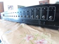
Hello, every one, I would like to introduce our new product "VT DSO-2810F" here. Together with the Multi-Instrument software, it turns your PC into a 2x100MHz Oscilloscope, Spectrum Analyzer, Multimeter, Signal Generator. (Note: The Signal Generator function is available via sound card or other DAC device, rather than the VT DSO-2810F unit). The unit is small, portable and has a metal enclosure. The price is US$250 (FREE shipping worldwide).
The Multi-Instrument software can be downloaded and tried for 21 days with full functionality using your computer's sound card for ADC and DAC at:
www.virtins.com/MIsetup.exe
or
www.multi-instrument.com/MIsetup.exe
Turn a PC into multiple virtual instruments!
1. Package Contents
1) VT DSO-2810F unit with a hardware bundled Multi-Instrument Standard software license
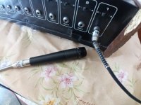
2) 2x100MHz Oscilloscope Probe P2100 with two switchable positions: x1, x10
3) USB cable (1.5 m)
4) CD (contains the copy-protected Multi-Instrument software and VT DSO-2810F driver)
2. VT DSO-2810F Hardware Specifications
1) Sampling Frequency: 100MHz, 50MHz, 20MHz, 10MHz, 5MHz, 2MHz, 1MHz, 500kHz, 200kHz, 100kHz, 50kHz, 20kHz
2) Analog Bandwidth: 40MHz
3) Number of Input Channels: 2
4) ADC Bit Resolution: 8 Bit
5) Input Voltage Range: (+-)1.2V*, (+-)12V*, (+-)24V* (one selector for two channels)
6) Maximum Allowed Input Voltage:
(+-)1.2V*: <= (+-)10V
(+-)12V*: <= (+-)24V
(+-)24V*: <=(+-)24V
7) Coupling Type: AC/DC (one selector for two channels)
8) Input Isolation: No
9) Terminal Type: Referenced Single-Ended
10) Buffer Size: 2000 bytes per Channel
11) Scan Time: 20us~100ms (with buffer fully filled)
12) Trigger Source: CH1 only
13) Trigger Level: Around 0V
14) Trigger Edge: Rising, Falling
15) Trigger Mode: Auto (Free Run), Normal
16) Input Impedance: 1 Mohms , 13 pF
17) Rising Time: <10ns
18) Streaming Supported: No
19) Interface: USB
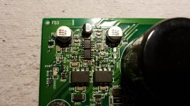
20) Casing: Metal
21) Device Category in Multi-Instrument: VT DSO F1
22) Power: Bus powered by USB port, no external power source required.
23) Power Consumption: Max. 1.5W
24) Dimensions: 132 mm (L) x 63 mm (W) x 24 mm (H)
25) System Requirement: Windows 98 or above
*Under these input voltage range selections, the actual measurement range is: -1.05V~1.12V, -10.5V~11.2V, -21V~22.4V respectively.
3. Introduction of Multi-Instrument 3.1 (Standard)
Multi-Instrument 3.1 (Standard) is a powerful PC based multi-function virtual instrument software. It supports a variety of hardware ranging from sound cards which are available in almost all computers to proprietary ADC and DAC hardware such as VT DSO-2810F, NI DAQmx cards and so on. It consists of a dual trace oscilloscope, a real time spectrum analyzer, a signal generator and a multimeter, and can run them simultaneously.
For a sound card based system, software triggering is supported. It features a specially designed data acquisition approach, which is able to monitor the input signal continuously without missing any trigger event before a frame of data is collected. It has a very fast screen refresh rate (typically greater than 50 frames per second). It supports sophisticated triggering method including pre-trigger and post-trigger. Both level trigger and differential trigger are supported. For a non sound card based system, the triggering capability depends on the hardware used. Hardware triggering is supported if the hardware used supports it. Software triggering is supported if the hardware used supports data streaming.
The software has a multilingual user interface, including English, French, German, Italian, Spanish, Portuguese, Russian, Simplified Chinese, Traditional Chinese, Japanese, and Korean. It has been widely used in education, scientific research, audio engineering, electronic engineering, medical diagnosis, vibration analysis, etc.
4. Functions of Multi-Instrument 3.1 (Standard)
A comprehensive range of functions are provided in Multi-Instrument (Standard), including:
(1) Oscilloscope
Oscilloscope Mode: dual-trace waveform, waveform addition, subtraction and multiplication, Lissajous Pattern, transient signal recording, voltmeter.
Record Mode: Record data to the hard disk continously until the recording process is stopped manually or 2 gigabytes of data has been recorded, whichever is earlier. During the recording process, acquired data will still be analyzed and displayed to keep the screen updated in real time.
Roll Mode: Data displayed in the Oscilloscope will shift left gradually while the newly acquired data are added from the right.
(2) Spectrum Analyzer
RMS amplitude spectrum, relative amplitude spectrum, octave analysis (1/1,1/3,1/6,1/12,1/24, 1/48, 1/96), frequency compensation, frequency weighting (A,B,C,ITU-R 468), moving average smoothing, peak hold, linear average, exponential average, measurement of THD, THD+N, SNR, SINAD, Noise Level, IMD, Bandwidth, Crosstalk, Harmonics, Peaks, and Energy in user defined frequency bands, phase spectrum, auto correlation function, cross correlation function.
(3) Signal Generator
Function generation, multitone generation, arbitrary waveform generation, burst tone generation, MLS generation, DTMF generation, musical scale generation, white noise and pink noise generation, and frequency/amplitude sweep signal generation. Fade In / Fade Out of the output signal.
(4) Multimeter
RMS, dBV, dBu, dBSPL, dB(A), dB(B), dB(C), Frequency Counter, RPM, Counter, Duty Cycle, Frequency/Voltage Converstion, Cycle RMS, Cycle Mean. The latter seven modes involves a pulse counting process, with the counter trigger level, hysteresis, frequency dividing ratio adjustable.
5. Extended use of the Multi-Instrument Software
With the VT DSO-2810F unit connected to the computer, the Multi-Instrument software will run under the licensed mode. In Multi-Instrument, the ADC device and DAC device can be independently selected. For example, you can use the VT DSO-2810F as the ADC device and your computer's sound card as the DAC device, and they can work simultaneously. Or, you can use the sound card for both ADC and DAC. Note: the test lead (or probe) for sound card is not included in this pacakge, but you can make the connection by yourself or purchase it from us separately.
6. Software License Information
Multi-Instrument has six levels: Sound Card Oscilloscope, Sound Card Spectrum Analyzer, Sound Card Signal Generator, Multi-Instrument Lite, Multi-Instrument Standard, Multi-Instrument Pro.
Multi-Instrument has five add-on modules/functions are: Spectrum 3D Plot, Data Logger, LCR Meter), Device Test Plan, Vibrometer.
The standard package of VT DSO-2810F contains one hardware bundled license of Multi-Instrument (Standard) without any add-on modules/functions. "Hardware bundled" means that the VT DSO-2810F hardware unit must be connected to the computer in order for the software to work under the licensed mode. Otherwise the software will work in 21-day fully functional trial mode. No softkey (activation code) and hardkey (dongle) will be given under the hardware bundled license.
7. Software Upgrade policy
Software upgrade in the same level is always FREE. When a new version is available, you can just uninstall your current version, download and re-install the new version, as long as the VT DSO-2810F unit is still supported by the new version.
Software upgrade to a higher level can be purchased from our webiste. The license bundled within the VT DSO-2810F hardware unit is remotely upgradable.
8. Refund Policy
One year warranty against defective materials and manufacutring defects for all hardware parts inside the package.
Return for malfuntional item is accepted for refund within 7 days after you receive the item. For full refund, the package must be in the same condition as received with all accessories. The delivery of the returned item must be prepaid by the customer. You must contact us first before you return it.
9. Screenshote examples


 ⚡
⚡


