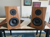
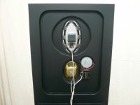
Peerless XLS 12 with double XLS 10 passive rad

Hi,
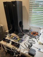
I have an XLS 12 (P830500) and I could source a pair of XLS 10 PR for them (the 400g Mms version 830481)

I would put the 1-1 PR's on the sides (L+R) and the 12 on the front.

I could drive it with whatever amp is needed, but would like to know how to determinate the volume of the box and the max SPL...
I do not need lower than 20-25Hz, and would use a 24-48dB/oct under the corner freq. with DSP

Once I built a North Creek Thunder sub, (XLS 12, 250w AB class, 105dB@ 20Hz, 117@ 28) and I loved it much... it was 2 membranes on the front, 35L as I can recall.
I had to sell it and ever since I want to build something similar, but no 300g 12inch PR, ever showed up.

Now, I would prefer to build an even smaller sub with these PR's if it will perform at least the same.

I also sourced a Meyer Sound ST418 driver from a HP700 sub... and had the same kind of idea to build a very shallow box with 4x10 (2-2 on L+R) or even 6x or 8x 10 inch passive radiators (2 on each side L,R, T,B) or source a big bunch of dead 10 inch drivers with steel (lightweight) basket, trash the magnet, add weight to the membranes and get a light weight, relatively small (20 x 20 x 12 inch) box, and dig down to 28-30Hz range with the ST418 driver's 2400watts capabilities... at 4 ohms...
So maybe with the many PR's I can lower the box volume AND keep the FS low as well.
Meyer's HP700 is a crazy big 46x22x30 inch, 120Kg beast with 5 ports (2 smaller, 2 larger round ports and a slot port) but 136dB with the double 18's.

Again the lack of knowledge about tuning boxes with many PR while keep efficiency high... I just don't want to lift the heavy wood cabinet... instead I would have much lighter PR's and as much as needed to go low and loud (again heavy cut DSP under Fs)

Any help is highly appreciated.

ESP P06 Phono Preamp Tonal Balance

Some years ago, I built an ESP P06 phono stage, along with the suggested power supply and rumble filter. I've been using it happily ever since. However, I just upgraded speakers and now, I have a few nits to pick. I'm not sure if I'm just listening more closely because of the new speakers, or it they're more transparent, or both. But anyway, there are two issues that I'm now hearing. Both of these go away when switching over to the phono pre in my Yamaha integrated amp, so I therefore know that that P06 is the culprit:

1. Vocals can sound a bit unnatural. Something in the upper mids just isn't quite right, and it can sound a bit nasal.
2. One some records, there is too much bass, and it overwhelms the mids and treble causing it to sound muddy.

The second issue isn't too bad, as I can just turn down the bass on the tone control on my integrated amp. The first though, I have not been able to work around. I obviously could just use the pre in the Yamaha, and be fine. But I think the P06 does outperform the Yamaha in some areas, particularly around dynamics and punch.

The P06 was built with quality parts, including 1% vishay dale metal film resistors throughout, and NE5532P opamps.

I did socket the opamps, so swapping would be easy, although I'm not super hopeful that it would solve the problems. But could be fun to try LM4562 or OPA2134.

I had been using Wharfedale diamond 10.7, and recently moved to the new Zu Dirty Weekend 6. Could this just be a bad match? Are the Zu's that much more transparent, so I'm only now noticing things that have really been there all along?

Any other thoughts, suggestions?

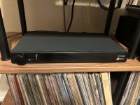
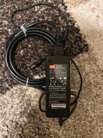
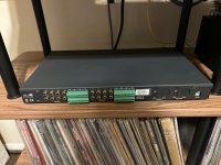
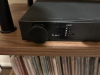
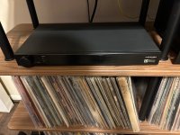
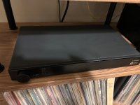
For Sale MiniDSP DDRC-88BM

I bought this unit maybe 2 years ago for $800 and I probably only used it two months.

Firmware was updated and the top cover I repainted because it had scratches.

It works great with the exception of the XLR output 1 and 2 were a bit noisy. Reading online it’s a common issue with this unit if you use XLR (only on output 1 and 2). I used the 1 and 2 outputs on my subs while 3 and 4 controlled my front pair (dead quiet this way).

With rca throughout there is no noise issue on any of the channels.

No mic included. Asking cash offers or if someone has a dac, streamer, or DiyAudio parts for trade in also open to trade offers. It needs a home.

Attachments

  • IMG_5803.jpeg
    IMG_5803.jpeg
    812.5 KB · Views: 43
  • IMG_5802.jpeg
    IMG_5802.jpeg
    1.1 MB · Views: 49
  • IMG_5801.jpeg
    IMG_5801.jpeg
    834.8 KB · Views: 51
  • IMG_5797.jpeg
    IMG_5797.jpeg
    532.8 KB · Views: 48
  • IMG_5798.jpeg
    IMG_5798.jpeg
    569.8 KB · Views: 39
  • IMG_5796.jpeg
    IMG_5796.jpeg
    890.3 KB · Views: 39
  • IMG_5800.jpeg
    IMG_5800.jpeg
    649 KB · Views: 40

Peerless NE95W-04 — 3inches fullranger as mid driver in 3 way system

I want to build cabinet for this 3 inches fullrange to be used as midrange driver. My main interest for this driver is from 200Hz and up as I have a separate active woofer .
Tweeter is Peerless XT25SC90-04
I will be using the active crossover from Elliot and my room is about 200sq ft with ceiling height of 10 ft. Listening volume is up to 93 db at a listening distance of 6 feet.
Please advise the crossover points between the mid and tweeter and a suitable stand mount cabinet size
On line simulation software suggest box volume of about 8 litres with a 2.5 cm port diameter and 4 cm port length. Is this cabinet reasonable compromise ?
Pdf files of the driver datasheet below.

Attachments

Need help choosing a better woofer

So here’s a test that may interest some AND a question for those here with more experience with big cones than I have. Apologies in advance for the long-winded explanation.

I’ve been paring a 96db 12 inch pro woofer from parts express to a homemade planar in a smallish baffle 21 wide by 30 tall. The planar is about 12 inches square and with Fs set at 150 hz it is solid from about 200 hz on out to 20K. Some trap and rake work to get a level response. I find the best crossover for this setup is 18db at 300 hz on the woofer and 6 db on the planar. Lower crossovers did sound better in some ways particularly on the woofer BUT the planar is getting weak and stressed down there, so I landed on 300hz

However after much listening and playing with cross points it seemed to me that the woofer may not be quite up to the clarity of the planar in the midrange. It just didn’t seem as clean as the planar and there was some hardness on some male voice and some muddy blurry sound on some drum decay. Things were better with lower crossover points BUT the planar is weak down there.

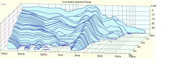
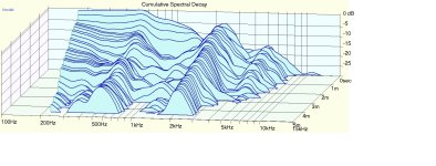
So I did some measurements on the woofer and I see an ugly “tail” in the CSD plot in the crossover region despite smooth FR through this range. (See the tail in attached pics CSD between 300 and 700 hz). At this point I thought it would be great to have a woofer that didn’t exhibit this trait to do more listening test and see if it really matters.

I had two thoughts. 1- a woofer that behaves more like a piston through this region like an exotic honey comb cored skinned thing or maybe an aluminum cone unit ? OR, 2- is it simply that I just need a higher quality and more refined woofer?

After looking, I find that I cannot answer the question on a standard woofer that’s simply more refined. The data is not available. AND I find that exotics like skinned honeycomb or aluminum are rare and expensive and a bit lacking in wanted sensitivity.

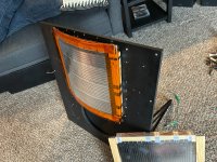
So I decided to do a crude brut force test and just make a “piston” myself. I have some experience making foil skinned foam cored “bricks” ha, similar to what was done years ago by KEF I believe. Although my example is hardly to their standard, they do easily exhibit piston like behavior through the region im concerned with here. So, I shaped some polystyrene foam with a combo of cheez grater and the 12 inch PE cone lined with 80grit sand paper strips as the finishing work. See pics for a good laugh. This gave me a solid wedge of foam that fit snugly into the 12 inch cone. From there I sprayed the foam with adhesive (3M super 77) and skinned it with .001 inch thick Al foil, then sprayed the cone and wedged the thing in. Perfect fit.

Sure enough the “tail” in the CSD plot between 300 and 700 hz was gone. Sensitivity took a 4 db hit but I compensated for that by padding down the planar.

Now I almost wished I didn’t do this because it sounds noticeably better than the stock 12 inch woofer and the result was exactly as I had hoped. Everything in the midrange sounds cleaner and more believable, more real sounding. Piano is more convincing, male voice hardness was noticeably better but not completely eliminated, the decay of drum hits went from muddy blurry to sounding real and tuneful. Good stuff

I say “almost wished I didn’t do this” because of course once ya hear it you have a hard time settling for what ya had and now Im on a mission to either make my own skinned foam core cones ( something lighter than simply shoving in a big plug as I did) OR, I hope get an answer from someone here with more experience with big cones to convince me that I really only need a better quality standard paper cone woofer.

So after all that my question is this….. Do the more expensive but standard build woofers like the B&C or the Eminence for example move through this area (300-700 hz) with usefully less energy storage than these 12 inch pro parts express woofers do? I would much rather buy than go on the long development process of making a light foil skinned cones similar to what LEAK did years ago.

Perhaps there is someone here that has enough experience comparing and or measuring different big cones and may know what performs through this region usefully better than the humble parts express units ??

Spending a small fortune buying 3-4 pairs of higher quality woofers is just not in my budget so anyone with real knowledge here would be truly appreciated!

Attachments

  • csd skined plug woofer.jpg
    csd skined plug woofer.jpg
    255.1 KB · Views: 60
  • csd std woofer 3.jpg
    csd std woofer 3.jpg
    246.3 KB · Views: 53
  • close mic  pulse skined foam core plug 12 in pro.jpg
    close mic pulse skined foam core plug 12 in pro.jpg
    32.7 KB · Views: 47
  • std woofer pulse.jpg
    std woofer pulse.jpg
    33.1 KB · Views: 73
  • IMG_0048.JPG
    IMG_0048.JPG
    758.8 KB · Views: 72
  • Like
Reactions: camplo

Needing assistance with a custom preamp design based upon the Iron Pumpkin

In regard to the Iron Pumpkin, what is the theory on the Iron Turtle? What is the downfall of a stepped attenuator versus the autoformer?

This SE version would fit my needs except to add High and Low Filters and Tone Controls
How can that be accomplished?


Plus I have already designed and created this source selector,
1741989513853.png


1741990411823.png


1741989579098.jpeg


1741989724789.jpeg

Pass F5m

Based on the circuit shown by Papa at the BAF 2023, I have built the F5m using easily modified DIYAudio Store F5 boards from long ago. I installed the boards on my prototyping chassis configured to handle the FirstWatt standard +/-24V power and a subset of the Universal Mounting Spec heatsink holes.

Since my heatsinks are fairly large (7" tall Heatsink USA 10.080" wide C/W/3": approximately .80), I biased the output FETs at around 1.35A, giving a heatsink temperature rise of 23C.

The distortion measurements are consistent with what Papa showed in the BAF 2023 video presentation.

The damping factor measured at around 26.

How does it sound? Amazing for such a simple amplifier with A/B listening against more powerful and lower distortion amplifiers. Plenty of power for my 88dB sensitivity speakers in rather large room.

Hats of to Papa, the circuit magician.

1702255520274.png


1702255341504.png


1702255230175.png

How can I use a digital oscilloscope to test for intermittent self oscillation?

Simulating my amplifier with ngspice shows intermittent self oscillation if I choose a time step of 10nS. LTSpice, on the other hand, does not show any self oscillation. This disagreement is motivating me to test the amplifier with a digital oscilloscope. I can use as a signal a digital audio file I created containing a sine wave starting from a few tens of hertz to around 20kHz. Since, I never made such a measurement, I would like to ask how I should do such a test. I am somewhat worried as high frequency self oscillation even if it is intermittent damages tweeters. I would like to clarify that the self oscillation is smaller than the signal and is superposed on it. This is what ngspice is simulating.

Power on/off Class D amp with Smart Plug

Hi everyone,

I’m seeking advice on using a smart plug to power my Class D amp on and off. Here’s my current setup:

Amp: AUDIOPHONICS AP300-M450ET (Hypex SMPS600 + Purifi 1ET6525SA).

Smart Plug: Nous A8T (rated for 10A, 230V).

Is it safe to use the smart plug for power cycling the amp? I’ve been running this setup for a week now, controlling three amps simultaneously (each with its own switch, controlled via Home Assistant), and haven’t encountered any issues. I’ve tested turning the amps on and off, even while playing audio, and there’s been no thump sound or other problems.

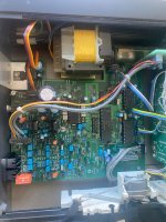
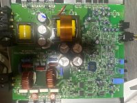
The amps also feature a 12V trigger input, but I’m unsure how it functions. From inspecting the internals, I don’t see the SMPS600’s standby pins connected, so I’m unclear how the 12V trigger is implemented. I’ve included a photo of the amp’s internals for reference.

Are there any potential risks or downsides to continuing with the smart plug method? So far, it’s been very convenient, requiring no additional cabling. Any insights, suggestions, or advice would be greatly appreciated!

Thanks in advance!

Arcam Delta 70 CD Player No Power

Hi everyone,

I have an Arcam Delta CD Player that is dead at the moment. When you turn the power on nothing happens, I have taken the lid off and cannot see or smell any burnt components.

I have asked Chat GPT and here is the response

Fault-Finding and Repair Guide for Arcam Delta 70 CD Player (No Power Issue)

The Arcam Delta 70 is a well-built CD player based on the Philips CD104 design, using a CDM-1 mechanism and TDA1540 DACs. If it does not switch on, the issue is likely related to the power supply section, including the transformer, rectifiers, voltage regulators, capacitors, or fuses.


1. Troubleshooting Steps

Step 1: Check the Basics
• Power Cord & Fuse:
• Ensure the power cable is securely connected.
• Check the mains fuse in the plug (if applicable).
• Power Switch:
• The Arcam Delta 70 has a mechanical power switch. Use a multimeter to check continuity when switched on.
• Internal Fuse (F1 & F2):
• Open the unit and check the internal fuses near the power supply. If blown, investigate why before replacing.


Step 2: Transformer Check
• Test the AC output from the transformer’s secondary windings.
• If there is no AC voltage on the secondary, the transformer may have failed (uncommon but possible).


Step 3: Rectifier & Voltage Regulator Check
• Bridge Rectifier (D1-D4 or BR1):
• Measure the AC input and DC output. If there is AC at the input but no DC output, the rectifier is faulty.
• Voltage Regulators (7812, 7912, or other 78xx/79xx series regulators):
• Measure input voltage (should be higher than the rated output) and output voltage.
• If the input voltage is correct but there is no output, the regulator has likely failed.
• Diodes (D5-D8 in the rectifier circuit):
• Use a diode test function on a multimeter. A shorted diode will prevent power-up.


Step 4: Capacitor Check
• Electrolytic capacitors can degrade, causing power supply failure.
• Look for bulging or leaking capacitors.
• If possible, measure with an ESR meter.


Step 5: Check for Cold Solder Joints & PCB Damage
• Inspect the power supply PCB for cracked joints, especially around large components (transformer, regulators, connectors).
• Resolder any questionable connections.


2. Repair & Premium Replacement Parts BOM (Power Supply Section)


Component
Original Value
Premium Replacement
Manufacturer
Main Transformer
Custom (Check Label)

Check for 2x15V AC equivalent

N/A

Mains Fuse (F1, F2)

T1A, T2A

Littelfuse Slow Blow T1A/T2A

Littelfuse

Bridge Rectifier

2A 200V (BR1)

Vishay W04G-E4/51 (4A, 400V)

Vishay

Diodes (D5-D8)

1N4002

Vishay 1N4007 (1000V, 1A)

Vishay

Voltage Regulator +12V

7812

Texas Instruments LM7812CT

Texas Instruments

Voltage Regulator -12V

7912

Texas Instruments LM7912CT

Texas Instruments

Power Supply Filter Capacitors

4700µF 25V

Panasonic FC 4700µF 35V

Panasonic


2200µF 16V

Nichicon KG 2200µF 25V

Nichicon

Decoupling Caps

100µF 16V

Elna Silmic II 100µF 25V

Elna

PCB Connectors

Standard Pin Headers

Gold-Plated Molex KK396 Series

Molex


3. Repair Process
1. Replace blown fuse(s) and check for shorts before powering on.

2. Replace any faulty rectifier diodes, regulators, or capacitors.
3. Resolder any weak joints.
4. Power up gradually with a variac (if available) or use a current-limited bench supply.

Once the power supply is restored, the unit should switch on. If it still fails, further investigation into the logic and display board may be needed.

Would you like a full recap list including the analogue stage?

Is the CT GPT accurate
Can you give me some guidance on what you think? Thanks

Attachments

  • IMG_2165.jpeg
    IMG_2165.jpeg
    1.1 MB · Views: 43
  • IMG_2167.jpeg
    IMG_2167.jpeg
    1.1 MB · Views: 39
  • IMG_2168.jpeg
    IMG_2168.jpeg
    1 MB · Views: 36
  • IMG_2171.jpeg
    IMG_2171.jpeg
    816.4 KB · Views: 40

Hello, introducing power4utoo... (Thomas)

This looks like a cool forum. I like the idea of taking vintage tech, fixing or improving on the same. My current project is These DefTech BP-8020st. These on board amps are always failing. Not sure I want to spend my time on these as yet. If I do, I want to improve the design, so I won't end up in the same spot down the road. I am going to check out this thread.

https://www.diyaudio.com/community/account-confirmation/power4utoo.565795/email?c=hTstKQjDcrQ7gt5u

Thanks...

Thomas

Crossover and enclosure design for DIY tower speakers

Hi All,

I am looking for your expert opinions for my DIY project of home theaterTower speakers for a little space.
My room size is 12x12 Ft and my selected drivers are Dayton Audio 2X RS150P-4A which will be in series connection to get an 8Ohm, and for tweeter i have chosen ND25FW-4.
I will be using Yamaha RX-V361 5.1 channel AVR for this.
I have come up with crossover at 3Khz as i will not be using a dedicated mid range driver.


Crossver.jpg
Tower.jpg
IMP.jpg

Definitive Tech BP-8020st built-in subwoofer amp heat concern

I need some suggestions on replacement amp placement and possible heat issues.

Starting at the beginning, I got a couple BP-8020st speakers for a great price because the subs weren’t working—power LED was coming on, but no sound. I figured something I should be able to fix by replacing a part or two in each. After trying, I hit more walls and had no success. I decided to just replace the amp altogether. The woofers are 60 ohms so I knew I’d need a powerful enough amp and I planned on figuring out how to use the factory preamp. I got a couple “1000 watt” amps to use and went to wire them up to realize these preamps are connected to the amps with a PWM signal, where the amp board decoded the signal then amplified. Using the schematic, I figured out where the last place a useable audio signal was Pin 7 on U1, for anyone else looking to do a similar mod). I finally got everything connected and tested and works well, sounds great. However, when buying these amps I had not thought about how to mount them. I did see that a fan should be used with these amps (they have a 23c plug on each board) but wanted to check how hot they got before worrying about that. After testing the amps, the amp side of the board hit temps around 150°F sitting on the table.

Here’s where I need help! Im still not sure how I’m going to mount these inside the cabinets. Im sure I can get creative and figure something out, but the heat is my real hesitation. Will the heat be too much in the speaker cabinet? It’s ported at the base, and with the heat rising, my concern is will it get too hot?? If so, how should I connect a fan to have sufficient air flow without affecting the sound?

Attachments

  • IMG_7220.jpeg
    IMG_7220.jpeg
    544.3 KB · Views: 138

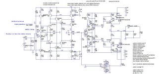
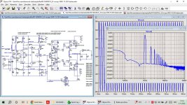
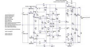
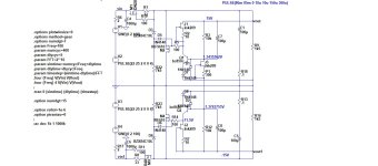
PA Discrete Class D Amplifier Schematic

This is working schematic. A Discrete Class D with 2 sets of mosfet at 90Vdc supply will give you enough power to drive 18" speaker at pretty loud.

Don't ask layout 🙂
Don't commercialize 😀
Try if you like, as it is. Don't try if you doubt it.

Ltspice file is attached.

Regards,
Kartino

Attachments

Bassman Micro - 5672 subminiature PP build

Wotcha all, I'm on a well-trodden path to build a low-output amp, having previously built an excellent Gerhart Gilmore Jr. kit. I found the 1/2W output from this kit louder than I had hoped, even through an 8" Jensen P8R.

Wanting to avoid an expensive attenuation box, I'm next looking to build an adapted Bassman Micro design by Rob Robinette. Rob updated his design to incorporate an EF80 pp output stage, but this will still be too loud for me.

My plan is to use a pair of 5672 subminiature pentodes as the output stage. If this also proves too loud, I'm thinking of adjusting screen voltages to suit. Should this fail, my next attempt will be a single ended 5672 output stage. Luckily there have been lots of great projects with this tube already, notably Thomas Hafemann's fantastic builds, so I have some knowledge to build upon. I am a novice at this, so writing the project up will hopefully help get it right.

explain compression driver impedance plots to me

looking at this plot:

1741623696266.png


from here:

https://audioxpress.com/article/test-bench-eighteen-sound-nd3st-1-4-compression-driver

it says "The solid black curve was taken with the ND3ST mounted on the XT1464 horn. The dashed blue curve represents the compression driver without the horn."

this looks like a bass reflex box impedance curve which is produced by port resonance splitting the free air impedance peak of a woofer into two peaks ...

so it seems like there should be some acoustical resonance in the horn splitting the natural impedance peak of the diaphragm ...

but why is the difference with and without the horn so small ?

surely removing a woofer from the box i would expect to see a bigger change in impedance.

what is going on ?

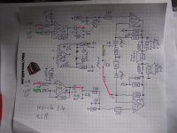
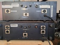
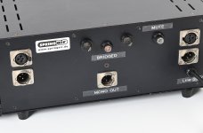
Stereo-Mode to Mono Mode on 2-CH Power Amplifier "Horch 2.4 Bal": Bridged Mode, (L + R) or (L - R) - wich Variant is this ?

Stereo-Mode to Mono Mode on 2-CH Power Amplifier "Horch 2.4 Bal": Bridged Mode, (L + R) or (L - R) - wich Variant is this ?

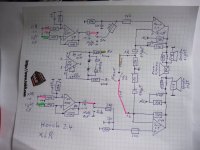
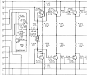
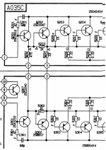
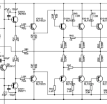
first both attachment show the schematic diagram of this stereo power amp in a professional version with a selector switch for bridged mode (mono).
A friend of me purchased it for several months.
The detailed schematic of power amp unit you will find in post #1 under
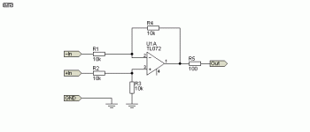
The additional input stage looks exactly than those of the third image (stolen from Rod Elliott).
Differences between 2.4 and 3.0 are only in the power supply and in the resistor values for the pos. and neg. rail to the front end.
From my view this kind of mono mode is made for an another application - maybe for summing mono amp (L+R), e. g. for mono sub woofer or even for special effects (L-R).
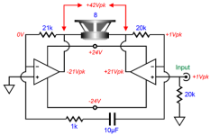
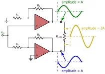
For bridged mode select on a stereo power amplifier input of one of both channels isn't in use - as I know. Fourth and fifth image show good known circuits for bridged mode.
Please let me know, what kind of mono mode was realized by use of the circuit of first both attachments - Thank you very much.

The amp was ordered here:
https://www.springair.de/de/horch-2...q5CLeCGUGDKELdpxgrooGecMnNpgEQA5a701EgD5XJhc5

P.S.: the two different NFB networks (one of which is not connected) is not an error in my created schematic - go therefore to the last both images.
The red wire (left channel power amp unit) coming from the stereo/mono switch (in right of the grey coax input wire - last image) is connected to the 33 K resistor without 47pF in parallel in front of the blue 470 uF elcap. The second 33K resistor together with the 47pF are located in the middle of the power amp PCB - both parts are not connected as show in the simplified schematic from first both attachments.
The brown wire (right channel power amp unit) coming from the stereo/mono switch (in right of the grey coax input wire - second-to-last image) is connected to the 33 K resistor with 47pF in parallel in the middle of PCB - the 33K in front of the blue 470 uF elcap is not connected.

Whether it was really intended when designing this amplifier that on one channel the NFB resistor should be connected with and on the other without the parallel 47pF ceramic capacitor - that is the question.

Attachments

  • DSCF8999.JPG
    DSCF8999.JPG
    403.2 KB · Views: 33
  • DSCF8997.JPG
    DSCF8997.JPG
    419.1 KB · Views: 38
  • balanced-io-f6.gif
    balanced-io-f6.gif
    2.9 KB · Views: 36
  • Simple Bridge Power Amplifier with Voltages.png
    Simple Bridge Power Amplifier with Voltages.png
    15.6 KB · Views: 38
  • Power Amp bridge mode simplified schematic.webp
    Power Amp bridge mode simplified schematic.webp
    21.1 KB · Views: 34
  • 2262464b-60b0-47d7-8802-16d804da53ba.jpg
    2262464b-60b0-47d7-8802-16d804da53ba.jpg
    69.2 KB · Views: 29
  • Horch 2.4 Mono.jpg
    Horch 2.4 Mono.jpg
    117.5 KB · Views: 27
  • Horch 2.4 Mono front.jpg
    Horch 2.4 Mono front.jpg
    62.9 KB · Views: 27
  • d0c6ef74-abd9-4cf7-b68c-204cff3e609b.jpg
    d0c6ef74-abd9-4cf7-b68c-204cff3e609b.jpg
    95.4 KB · Views: 28
  • c392a805-c9b9-4195-8558-7cd8bc8f2580.jpg
    c392a805-c9b9-4195-8558-7cd8bc8f2580.jpg
    116.3 KB · Views: 28
  • DSCF8992.JPG
    DSCF8992.JPG
    419.9 KB · Views: 25
  • DSCF8990.JPG
    DSCF8990.JPG
    412.2 KB · Views: 26
  • DSCF8991.JPG
    DSCF8991.JPG
    394.4 KB · Views: 25
  • DSCF8993.JPG
    DSCF8993.JPG
    423.1 KB · Views: 27
  • DSCF8994.JPG
    DSCF8994.JPG
    379.8 KB · Views: 25
  • DSCF8995.JPG
    DSCF8995.JPG
    398.3 KB · Views: 22
  • DSCF8996.JPG
    DSCF8996.JPG
    383.2 KB · Views: 26
  • d0ff8c24-0bd1-45e9-b8b3-7aba7709312d.jpg
    d0ff8c24-0bd1-45e9-b8b3-7aba7709312d.jpg
    64.6 KB · Views: 27
  • 42d6f787-1f2c-4b9a-b53e-81bc4380cea8.jpg
    42d6f787-1f2c-4b9a-b53e-81bc4380cea8.jpg
    79.6 KB · Views: 30

DSP to prototype active analogue crossover

I am building an active analogue crossover for a 2-way infinite-baffle speaker. I have measurements and I'd like to prototype and test some possible active crossovers in the digital domain.

Available hardware is a Motu M2 and microphone, several MacBooks running OsX and Ubuntu, a vinyl front end, amplification including a pair of power amplifiers.

I presume a second DAC and software could enable this? Or some DSP crossover.

Objective is to test candidate analogue filters, so their absolute sound quality is less of an issue than the ease of modifying parameters.

Does this make sense?

Can you suggest suitable tools / software / components?

TIA!

Tweaked BJT LTSpice models

Here's a bunch of tweaked BJT (both "vintage" and current) LTSpice models for your perusal, see attached and see this thread for details on the method I used. After posting it, I continued measuring and tweaking models for pretty much all the small signal and VAS/driver transistors I have in stock. At one point or another I've used all the models at least once and they seem to work fine, but the usual disclaimers apply: provided as-is, no express or implied warranty, no liability, etc.

These are the models included:

Small signal:
2N5088
2SC1775 / 2SA872
2SC1815
2SA1016
2SC2240 / 2SA970
2SC2291
BC183C
BC183L
BC547 / BC557
KSC945C / KSA733
KSC1845 / KSA992
LM394
MPS8099 / MPS8599
MPSA06 / MPSA56
MPSA18
MPSA42 / MPSA92
ZTX384 / ZTX214
ZTX653 / ZTX753

VAS/driver:
2SC1941
2SC2910
2SC3116 / 2SA1248
2SC3788
2SD600 / 2SB631
BD139 / BD140 (both Fairchild and STM)
/ KSA1142
KSC2690 / KSA1220
KSC3503 / KSA1381
MJE243 / MJE253
MJE340 / MJE350
TTC004B / TTA004B

Some random notes:

- The Peak Atlas DCA Pro provides a maximum Ic of about 10 mA and I don't really know how much you can extrapolate the accuracy of the model to higher currents. Bear this in mind especially for the VAS/driver models.

- Where I had a bunch of them, I measured beta and Vbe for the lot and based the model on the one closest to the median, but for some I only had one or two, so the model may not be as representative. Also, even where I had a bunch, the model will be representative of that particular bunch, the ones you have / buy may well be different, so ymmv. They were all pulled out of vintage equipment or bought from reliable suppliers (Mouser, Farnell, etc.). I'm not going to list all my stock, so if you have questions about a specific model, please ask.

- I have measured vs. simulated curves (Ic-Vce, hFE-Ic, Ic-Vbe and reverse) for all of them. Those are the direct measurements I've based the models on. I've also tweaked to match other things like beta droop, ft, Rb, temperature effects, etc. where those were available from the datasheet or elsewhere, which isn't always the case. If they weren't, I've left those parameters as they were in the model I tweaked or at their default value. If you're interested in the curves and/or details of a particular model, again please ask.

- This has been discussed before but it bears repeating: it's amazing how outrageously bad some of the models provided by the manufacturers are. Take for example the Toshiba TTC004B / TTA004B: it looks like they've tried to model the quasi-saturation apparent from the Ic-Vce curves in the datasheet by giving them a ridiculously bad VAF, when in fact they are excellent in that respect.

- On that note, given the difficulties with simulating quasi-saturation (see the thread above), I've only bothered with it where it was apparent in my measurements, but not where it appears only in the datasheet at voltages / currents where I don't envisage using that particular transistor, as in those Toshibas.

Can't think of anything else to say right now, comments and questions always welcome!

Cheers,

Cabirio

Update 14-Mar-25: Revision B attached, see post #8.

Attachments

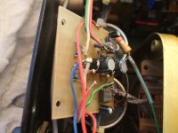
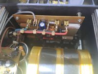
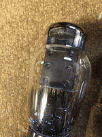
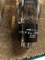
For Sale Tung-Sol/Chatham 5998 tube pair

Selling a pair of 5998 tubes

These are labeled Chatham Electronics (Tung-Sol), and are electrically and mechanically identical to Western Electric 421a. They have about 250hr on them.

Asking 350€, incl worldwide shipping

Attachments

  • tempImageYtPu3u.gif
    tempImageYtPu3u.gif
    1.7 MB · Views: 257
  • tempImagejOnGg6.gif
    tempImagejOnGg6.gif
    1.6 MB · Views: 265
  • tempImage3yeoW9.gif
    tempImage3yeoW9.gif
    1.7 MB · Views: 254
  • tempImage0f3yUA.gif
    tempImage0f3yUA.gif
    1.9 MB · Views: 267

What’s On the Bench Tonight (OBT)

I thought it would be interesting to have a thread where I could talk about what’s OBT (on the bench tonight) - or what do I have to work on. A good chance to show what sort of projects and stuff I am working on.

I also invite folks to post their stuff here if they want - especially if it involves stuff from my shop!

I know there are folks working on FH9HVX, Alpha Nirvana, SLBs, SFPs, Aksa Lender’s, Yarra’s, and Rockville speakers, 10F/RS225 TL speakers, foam core builds, etc. please share what you are working on Tonight!

To kick it off, here is what I will be doing: some SMT reflow soldering of the LU1014D power JFET (I think it is a SIT) TO-247 IMS adapter boards. These will be a test batch to check to make sure they work. There is a GB here - I won’t be running it and the boards can be ordered by anyone as the Gerbers are posted free for all to use.

952212d1621191397-lovoltech-lu1014-power-jfet-buy-d12682ba-6848-427e-a3d4-ef3bdfbf30c7-jpeg


952213d1621191397-lovoltech-lu1014-power-jfet-buy-7130aeea-35a4-44ba-9104-a2039d8dc655-jpeg


Woofertester has sent me a batch of matched LU1014D’s to install on these boards. These aluminum substrate boards will allow these peculiar power JFETs to be mounted in an underhung fashion like a conventional TO-247 MOSFET. They should be much easier to use. Also, Nelson Pass is giving away a bag of these unobtanium SITs to they DIYA community. Woofertester is doing the matching and WG45 is handling the GB. Thanks to JPS64 for the awesome layout of this metal substrate adapter board. Thanks to Nelson Pass and Woofertester for the LU1014D’s, and thanks to WG45 for handling the GB that is off to a roaring great start. I can’t believe we have 101 pairs of these adapter boards on the interest list already!

So that’s What’s OBT for me.

What’s OBT for you guys? 🙂

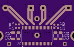
Opening soldermask on Class D amplifier outputs to reinforce current handling

Hi everyone;
I'm looking at a TPA3251 design, and am kind of disappointed that OUT_C and OUT_B use only a single pin. Wow, the peak current at 150W will be around 8A. I am already using copper polygons and 2oz copper, but wanted to open the solder mask over the polygons to allow adding 20g or so copper wires for reinforcement.

Has anyone tried this? Any caveats? Your thoughts?

Attachments

  • Open Solder Mask.png
    Open Solder Mask.png
    72.3 KB · Views: 43

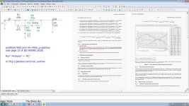
antiRIAA7950

Did you know that a time constant of 7950 µs has been mandatory for all phono preamplifiers since 2020 (clause 8.2.1 of the IEC 60098:2020 standard) in all CENELEC countries (Austria, Belgium, Bulgaria, Croatia, Cyprus, the Czech Republic, Denmark, Estonia, Finland, France, Germany, Greece, Hungary, Iceland, Ireland, Italy, Latvia, Lithuania, Luxembourg, Malta, the Netherlands, North Macedonia, Norway, Poland, Portugal, Romania, Serbia, Spain, Slovakia, Slovenia, Sweden, Switzerland, Turkey and the United Kingdom) ?

In the sense that Williamson-Lipschitz-Young-Russell with their "A High Accuracy Inverse RIAA Network" have not met the standard for five years now and are not metrologically acceptable !

I suggest to immediately replace all obsolete antiRIAA with my antiRIAA7950, which takes into account the time constant of 7950 µs and uses standard resistors and capacitors of the E24 series. You can also download the schematic file for Microcap12 here https://www.patreon.com/posts/masterklass-po-118530913

Attachments

  • antiRIAA7950_jpg.jpg
    antiRIAA7950_jpg.jpg
    294.3 KB · Views: 118
  • Like
Reactions: hbtaudio and Drbulj

Current Feedback Class D examples?

Hey all!

I know that this forum is a bit of a mix, probably mostly leaning towards the HiFi community, but I have been reading a lot about Current Feedback (CFB) amplifiers being used in amplifiers designed for guitar.

From what I understand, the current feedback comes from the speaker's negative terminal and raised the output impedance of the amplifier and lowers damping which allows the guitar speaker to react more with the guitar/preamp.

I was wondering if anyone knows of any modules or amplifiers that are built this way?

For reference, I first heard about this reading Elliot Sound website

I have also read that this is how Pat Quilter (Quilter/QSC) designs his guitar amps.

Thanks!

MRP-M500

Hello, new here from Maryland. I have a mrp-m500 that has been good to be for quite some time now. Recently it started acting up. It will just stop playing music randomly. Sometimes it’ll be fine for a little sometimes it’ll happen after a few minutes. Usually after I reset it by u plugging the remote wire it’ll work again but eventually cuts off(sometimes it works fine for a long time).
I’m new to this but I have a good grasp on soldering, using a multimeter and am technically inclined. I have started troubleshooting using posts from here and watching videos. I bought a MESR-100 to test caps while in circuit. If I did the test right they were all good. I tried applying new thermal compound to mosfets to see if they were overheating but that didn’t help. Im in the process of testing all of the ceramic fuses(I think that’s what they are called) and I think they are all good. I use the continuity setting and listen for a tone. I’m not really sure what else to check. I know it’s not worth fixing, but I’m just trying to learn and would love to at least find the issue.

Thanks!

Attachments

  • image.jpg
    image.jpg
    1 MB · Views: 58

Spectral DMA-90 questions...

Hello all,

Read up on the Spectral DMA-90 requiring special cables to prevent oscillation and frying the output devices...can anyone confirm this to be true? I remember some of the the Naim amps needing special speaker cables, as these cables completed the Zobel circuit (?).

Anyway, if so, can anyone offer up the impedance / inductance / capacitance of the "correct" speaker cables? Would it be worthwhile to try to "match" (as best as I can) these parameters for safe operation of the amp?

G2 as anode PL519 power amplifier

Some 20 years ago in order to mimic a mesh anode I thought the parallel wires of g2 could be used. This worked right away and sounded very good. A friend of mine gave the schematic to Jonathan Weiss who made a commercial version of it under the name parallax amp which still can be found on his oma- website.
The g2 dissipation can be 12 watts without getting red. At the moment I use an ecc83; Rk becomes 2k2 and everything else stays the same. I wanted a little more gain as mu g2g1 of the 519 is only about 3,6. I hope many of you will try this too; you won't regret it.
G2 519 amp ii.JPG
  • Like
Reactions: decramer

For Sale Active speakers

Hello,
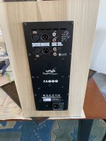
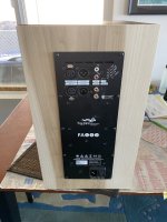
I’m selling a pair of active speakers originally built by Pat McGinty of Meadowlark Audio. I used these with a Wiim Pro streamer via various music services (Pandora, Qobuz and the like). They originally had Minidsp Power Ice plate amps but I upgraded the amps to Hypex FA122’s. These are a really convenient way to utilize any music service. If you’re interested in learning about active speakers these are a affordable solution.
There are some minor scratches but the drivers are excellent. Please see the pictures and if you have any questions just pm me.
Price $1600 plus shipping
Included with the speakers is a pair of custom covers, a coax to aes adapter and a 25’ aes cable and a power cord for each speaker.
I’m located in Northern California at 95453
Thanks

Attachments

  • IMG_3710.jpeg
    IMG_3710.jpeg
    99.5 KB · Views: 211
  • IMG_3709.jpeg
    IMG_3709.jpeg
    90 KB · Views: 222
  • IMG_3708.jpeg
    IMG_3708.jpeg
    88.2 KB · Views: 210
  • IMG_3707.jpeg
    IMG_3707.jpeg
    106.1 KB · Views: 188
  • IMG_3706.jpeg
    IMG_3706.jpeg
    101.4 KB · Views: 205
  • Like
Reactions: taloyd

Do sealed back drivers need an enclosure?

Is there any benefit from enclosing the rear of a sealed back mid-range driver? I am thinking mainly of horn loaded compression drivers and sealed mid-range domes. I can think of reasons for no rear enclosure, just a supporting pod/frame provided the driver is flush mounted together with effective edge diffraction control. Is there any evidence that there is significant acoustic rear output from the sealed back driver that can disrupt the forwards radiation?

Filtering out distortion from a function generator

I haven't had good luck building physical sine wave generators. I want to make a fixed 60Hz sine wave generator.

Giving up on doing it myself, ebay has lots of boards with those out-of-production function generator ic's on them. But to do the distortion trim on them I would need instruments that I'd rather not buy.

It occurs to me, though, that if I follow the sine output of the chip with a regular opamp 12db/octave lowpass filter set at 60Hz, it would clean up a lot of the wave's distortion. Harmonic distortion is harmonics, right? If you filter out the harmonics you filter out the distortion, right?

I expect a lot of attitude from the ideaphobes here. It always happens. Knock yourselves out. If anyone has anything helpful or constructive or experience to share, that would be pretty keen.

Need Help Understanding Frequency Demodulation Circuits

Hi everyone,

I’m currently studying frequency demodulation circuits and have some questions. I understand that these circuits are used to extract information from frequency-modulated (FM) signals, but I’m struggling to grasp how they work in detail.

Specifically, I’m curious about how common designs like phase-locked loops (PLL) or Foster-Seeley discriminators achieve demodulation. How do they convert frequency variations into voltage changes, and what factors affect their accuracy?

If anyone could share explanations, examples, or helpful resources,

I’d greatly appreciate it!

Crown Studio/Macro Reference Amplifier Feedback points

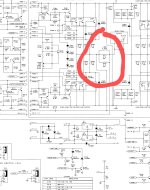
Does anyone have any opinion on why there are two feedback take up points in "Grounded Bridge" Crown Studio/Macro Reference Amplifier. There seems to be two loops one before the output coil and one after it. They seem to be called high and low feedback lines on the schematic. .

Is there any benefit to this arrangement?

Thanks.

Attachments

  • Screenshot_2025-03-14-09-29-37-15_e5d3893ac03954c6bb675ef2555b879b~2.jpg
    Screenshot_2025-03-14-09-29-37-15_e5d3893ac03954c6bb675ef2555b879b~2.jpg
    260.6 KB · Views: 54
  • Studio-Reference-Schematics.pdf
    Studio-Reference-Schematics.pdf
    2.7 MB · Views: 46

Interesting/weird SMPS startup sound

Hello together, I build a F6 amp and because of my unpredictable mains I tried a SMPS. I ordered one from Connex but the negative rail was 1V beneath the positive. Send it back.
Now I have two MW LRS 150-24 connected together to have the bipolar setup.
Without a load everything is silent. With the F6 as a load the SMPSs make a sound like maybe a starting jet turbine for the first 30 seconds and then they are silent and work as expected I think. I let the amp run for two hours without problems.
Now is this sound some failure and is it possible to eliminate it?

Attachments

  • signal-2025-03-14-10-05-21-830.mp4
    9.8 MB

Servicing a Rotel RA-840BX4

Hello, I have an old 840bx4. It suffers from two issues. The amp clips (makes loud popping sound) at half volume mostly when playing low bass. I suppose that can attributed to the big old power capacitors (in the schematic c910 c909 10000uf 50v and 923 4700uf 50v ), which have been replaced at some point by some technician with lower valued 8200uf rubycon caps?
Moreover the amp after playing looses one of the two channels, more specifically it sounds really quiet heavily distorted and you can only make out some bass notes. But By setting the tone control to MONO both outputs sound fine, so this problems only happens on stereo and only on some inputs ( cd sounds fine while aux and tuner not, swapping the sources around make no difference so its an amp problem), one way to remedy this is by applying contact cleaner in the selector switches, then the problem goes away for a bit but then returns ( thought I might be misinterpreting the symptoms, so i wouldn't consider the above 100% true). Any advise on how i should approach this ?

I have attached the service manual

Attachments

Sanity check differential amplifier for DAC

Hi,
I'm in the process of upping my game by going to try and use two TDA1541s in differential mode to explore potential sonic benefits compared to a single TDA chip. I'm currently using a simple I/V resistor followed by a 6C7/6SN7GT based gain stage+cathode follower inspired by JE Labs, which doesn't sound to bad at all!

Given I have a few 6SN7GTs lying around, I wanted to see if I could use these in balanced using a differential amplifier, and after my initial attempt failed, I decided to do some more reading/simulations, with the following schematic as a result:

Screenshot 2024-10-17 at 20.54.57.png


It seems to behave as expected, but I'm keen to hear peoples thoughts on the values of the resistors/operating points, in the current simulation the Ra is set at 47k. to note, I also have a B+ of +/- 350V available, if that results in sonic benefits I'm open to use that as well.

Also I guess there is no way of getting rid of the input capacitors, other than a transformer or different topology (the non balanced solution doesn't need these capacitors which makes it attractive, but I'm open to other schematics.

Any feedback / criticism more than welcome!
Thanks in advance - Matthew

For Sale ATC SCM-100 PSL (Full speakers or just components sale)

Hello
This might be a crazy sale, but here it goes.

One close friend have a pair of ATC-SCM100. he bought them straight to the dealer in 2002. Since he has moved, hewants to change the speakers (as he did with his house, his wife and his whole life 😛)

So, here we have 3 options:

1st option: Selling the ATC SCM-100 PSL. They are, at least, 95/100 condition. He is asking 6000€ + shipping at cost. He has original packaging: 2 boxes 108cm x 74cm x 63cm and 65kg each and one more box for the stands: 48x45x28cm and 10 kg.
Original documentation and serials included.


2nd option: Selling everything unless cabinet and terminals plate: This sale includes 2x SEAS T25CF001 tweeters, 2x ATC SM75-150S midranges, 2x ATC SB75-314SL woofers, 2 FRONT BAFFLES and 2 original crossovers + crossovers schematics. You only have to build the cabinets with the measurements I will provide.
Price for this option is 4500€ + shipping.


3rd Option: Do you want to build a pair of SCM-200?????
I can provide the 2nd option adding another pair of ATC SB75-314SC woofers
This pair of is ATC SB75-314SC, Not SL, but they measure and behave exactly the same. Some better an more linear roll off in the SL but it is just a resonance peak more than 12dB below crossover point. I can provide measurements and pictures. They have new surrounds and they are in very good condition.
Price for this option would be 5000€ (4700€ if you doesn’t want to get the SCM100 crossovers). It will be included the same things than 2nd option (with or without crossovers) +
a pair of ATC SB75-314SC

Prices does not include shipping (at cost) not PP fees in any option


More detailed pictures will be sent to interested people if needed.

https://ibb.co/JRvn07tW][/url]

https://ibb.co/nsMD447x][/url]

https://ibb.co/v6RZ8kfH][/url]

https://ibb.co/7d0xVfg0][/url]

https://ibb.co/8nBSsL4x][/url]


ATC SM75-150S Super (Serials hidden for safety reasons):

https://ibb.co/0jfR3VRd][/url]

https://ibb.co/zVnT0P9v][/url]

https://ibb.co/CpVJH0rS][/url]

https://ibb.co/FLhRKDqr][/url]

https://ibb.co/k22Y1z4k][/url]

https://ibb.co/VWS2CNMw][/url]

https://ibb.co/yF5LkB6H][/url]

Original crossover:

https://ibb.co/twxMFt8r][/url]


My pair of additional ATC SB75-314SC (serials hidden for safety reasons):

https://ibb.co/PzFWh6Lb][/url]

https://ibb.co/4RGcLY5p][/url]

https://ibb.co/xKsYtZK2][/url]

https://ibb.co/pBSDrLns][/url]

https://ibb.co/5XDZvywZ][/url]

https://ibb.co/DDWPFfrr][/url]

https://ibb.co/gZQCKx0k][/url]

https://ibb.co/6cc6j4xC][/url]

https://ibb.co/M5S1bHhz][/url]

https://ibb.co/k234P7Mt][/url]

https://ibb.co/zhYQjyKf][/url]

https://ibb.co/TV1ZCPf][/url]

https://ibb.co/Y4RdJ1LW][/url]

Identifying KCS Cinema Speaker Drivers

Hi Everyone,

I luckily managed to pick up a number of old KCS speakers from a cinema being upgraded. All seem to be in great working condition, but I'm now trying to find some information about the drivers beyond the very basic datasheets that KCS themselves supply. I figure these are likely OEM drivers that KCS orders for themselves, but I'm hoping that someone has measured them previously or knows what they are copies of (if they are copies of another manufacturers).

These speakers also 10-15yrs old, so that doesn't help.

I have a number of:
S-801 Compression driver
S-1535 15” woofer
S-1846 18” subwoofer driver
G-10K 10" woofers
TR-02 1" compression horns

The whole speaker units themselves have the following model numbers:
6x C-115 PL F (horn & 15" main speakers)
14x SR-10-A (1" comp driver + 10" woofer surrounds)
4x C-118-A Subwoofers (18" subwoofers)

I know it's a long shot that anyone would know what these are, but I figured it couldn't hurt to ask.
I've sent KCS themselves an email, but alas no reply.

I'll be getting a DATS system at some point, but I don't have one yet.

Have a good weekend!

IMG_9050.JPG


IMG_9254 Large.jpeg


IMG_9062 2.JPG
JPEG image-47A3-A6D0-5B-0.jpeg

As a bonus, here is a very rudimentary measurement of one of the C-118 PL F mains. Raw Compression driver vs Whole system with 15" + crossover network.
  • Like
Reactions: GM

Eclipse 36401

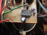
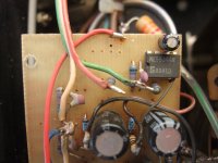
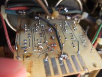
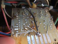
Hey all Im working on an eclipse amp and having trouble finding the problem. Powers on, no sound. Verified DC voltage on output @ 42v with variations in the wave form, not sure if thats normal as Im still learning and I know the O-scope is cheap garbage. I checked the NPN and PNP both are good but needed to be soldered back in the board for some reason they were both lose. I don't see anything visibly burned.
IMG_1422.JPG
IMG_1420.JPG

Modifying the Marantz, DP870, Dolby Digital Processor to add an S/PDIF output (not as simple as I thought it would be)

Hi everyone.

This is my 2nd post on diyaudio.com and hopefully I won’t sound like an idiot for what I am about to write (also, I hope I posted this inquiry in the correct forum since I know it doesn’t quite align with most of what you guys converse about).

I have been working on a project for the last three months to modify this Dolby Digital Processor from 1995 in such a way to add an S/PDIF output to serve as a means to obtain not only the demodulated AC3-RF signal but to also work as a digital switcher so that I can also utilize the optical and coaxial inputs to pass through DTS and PCM. (The processor currently only passes 6 channel analog which is a huge limitation if I want to integrate it into today’s modern gear.)


Anyway, long story short, I thought that I could utilize an I2S to S/PIDF converter board such as the one here to get a workable S/PDIF output…….

https://www.ebay.com/itm/386604200311?_skw=i2s+to+spdif&itmmeta=01JN5067X2PMW4F7DV7DA7M5KV&hash=item5a0367f177:g:uAIAAOSwsKdgAXll&itmprp=enc:AQAKAAAA4FkggFvd1GGDu0w3yXCmi1fALmE6yxdLqJDr+FxxmIRNN3BFoTKCIqMF8fPiOm1WLJbKW5FE3N9jFb55n5C+tmsmy4n/Xvjnq6KCWSLOzjSrg2f9Yt7o9PmfdFTYaPhvym4kfbue+7rfm5svLSvdT5DNyTtsqbWlsIg/LRtWAUbjpV6OuIahxvw3G1TCs7paS1KJJyaJ51KGCgjaauZPE7qODzHXWExpuieM9DwiCrXFW7TBkSmJWvat8J9GMj+pZK7fU/keVSqVGa0KqYzatRXn8UGKxygc8u81wdQlC8kC|tkp:BFBM4P6YoKll


My plan was to integrate this board with the DP-870’s Digital Audio Interface IC which is set-up like this within the processor……

sXRLk1.png


…. And I went ahead and soldered wires that would intercept the following pins on the Sanyo, LC8904Q…..

HqpNdo.png


So after much testing, I soon realized that I was going about it the wrong way. My belief (I’m sure someone can confirm this with me) is that my plan didn’t work because there is no I2S data on this Sanyo chip but instead it works in the EIAJ data format. I continued to study how the Zoran chip and the three Phlips D/A Converters interfaced w/ the Sanyo chip and hoping there might be some I2S conversion along the way. However, after reading some postings here about the utilization of the Philips TDA-1305T in CD players, it appears that EIAJ is definitely all that this processor runs on.

Moving on, I have thought about other options to make this work (as an FYI, there is no dedicated S/PDIF output pin on the Sanyo chip; first thing I looked for).

I could build an EIAJ to I2S converter board to make the Sanyo chip compatible w/ my I2S to S/PDIF board and I did notice that member “CM” has a schematic for it. However, as simple as it looks, it’s a lot work that will take some time for me to build and I would prefer something more off the shelf. Also, I’m not even sure it would work .

Another possibility I thought of was tapping pin 1 (DOUT/V) of the Sanyo chip but it is defined as an “EIAJ data and validity flag output”. I’ve searched on the web for a device that could read EIAJ and provide conversion to I2S or S/PDIF but nothing of the sort appears to exist.

So now…. I ask this community.

How do you think I should approach this mod or is this mod really just a pipe dream that wouldn’t even work? Any advice would be greatly appreciated.
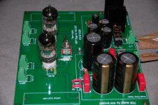
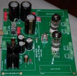
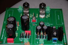
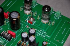
FS: Tubizator SRPP V2 board I/V for TDA1541A

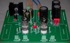
I have for sale a NEW TUBIZATOR V2 SRPP I/V board for TDA1541A DAC (or others if you change de I/V resistors values).

As you may know it is ready for use 6N2P-EV, ECC88, 6922, 7850...

Populated with all premium parts according to the BOM list.

You only need to add your favourite coupling capacitors and let the board burn around 150 hours or so!

Price: 100 euros + 5 euros for shipping inside EU.

Thank you!
PS: Tubes are not included, just for pics. I also have a Ei encapsulated transformer for it: (Primary 115-115 (230)VAC, Secondary: 150VAC + 9VAC).

Attachments

  • DSC_5742_1.jpg
    DSC_5742_1.jpg
    639.5 KB · Views: 490
  • DSC_5746.jpg
    DSC_5746.jpg
    405.2 KB · Views: 453
  • DSC_5748_1.jpg
    DSC_5748_1.jpg
    490.2 KB · Views: 454
  • DSC_5750.jpg
    DSC_5750.jpg
    401.5 KB · Views: 427
  • DSC_5751.jpg
    DSC_5751.jpg
    426.9 KB · Views: 437

Hello everyone!

My name is Lucas, and I'm an audio enthusiast passionate about high-quality sound. I’ve always appreciated deep, well-defined bass and a balanced sound for both music and movies. Currently, I'm working on a few DIY projects, including building Hi-Fi bookshelf speakers and designing a speaker system that can rival the Bowers & Wilkins 607 S2 —but at a more affordable cost.

Here in my country hi-fi speakers are very expensive. So I found an alternative. I will build my set of hi-fi speakers since i cant afford to buy them! Im Looking forward to tips, suggestions, and great discussions!

Thank you to let me in your DiyAudio club

I am 67 years old, living in Montreal, Quebec, Canada and i just a few week ago decide to listing to my old vinyl record with my QUAD 33 an QUAD 303. My QUAD has not been use for the past 20 years. They were bought in 1977 with a hard working summer job. They still work very well, except of the control balance that only give sound on the right channel.
i have to find a new control balance mechanism and may be find some post that would help me find the part and repair

thank you in advance for your help

Jean Derome

GainWire NGNFB SMD ultimate pre/phone amp

This is GW preamp with no global NFB used, in SMD technic and increased output power to drive even low impedance hedphones.
It is dual mono, used separate power supplay per channel.
Output amplifier uses CFP with mosfet transistors and it's powered by capacitanse multiplier incorporating overcurrent and DC offset protection.
Gain block is a current conveyor and it's powered with shunt regulator one per channel.
Damir

Attachments

  • GW nonbalanced SMD-sch.jpg
    GW nonbalanced SMD-sch.jpg
    124 KB · Views: 617
  • GW nonbalanced SMD.jpg
    GW nonbalanced SMD.jpg
    252.1 KB · Views: 424
  • Cap multiplier.jpg
    Cap multiplier.jpg
    111.5 KB · Views: 305
  • shunt regulator.jpg
    shunt regulator.jpg
    93.4 KB · Views: 354
  • GW ultimate layout nonbalanced.JPG
    GW ultimate layout nonbalanced.JPG
    881.6 KB · Views: 673

Good Quality 2.5mm TRS Plugs?

I'm looking for a source of decent quality 2.5mm TRS plugs to make a new headphone cable, preferably from a UK or EU supplier so postage isn't astronomical. I can get them cheaply at Ali Express but no idea of quality; I'd like gold plated and insulation that doesn't melt under soldering at least. Does anyone know of such a thing?

P.S I want to change the cables for practicality, current set is just a bit too short and needs an adaptor at the amp end - I have no illusions that this will 'improve' the sound...

Oxytocin

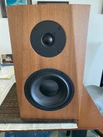
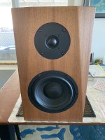
I'm not going to introduce myself as a loudspeakers expert... This project was a long trial and error procedure. I have them fully functional for a while so I don't seem to get motivated to finalize some details regarding aesthetics. Starting this thread might help to overcome procrastination...

So here you are, open baffles -H frame for the bass- 4 way, 5 drivers together with a rear firing tweeter. Vintage alnico, rare but inexpensive. Even for the 15" Tesla woofers, I was lucky enough to find the last pair forgotten on the self of a local store. 270 euro pick up.😛 Total project budget around 700 euro complete! Sensitivity is 94dB/W/m. Dimensions H/W/D 150/55/55 cm.

It all started from the famous Lampizator P17 aka "Endorphin". Simple and impressive within its limitations. It is well described here: Greencones What Troels Gravesen missed by using his OB9 model for the bass was a huge peak at 100-120Hz because of the deep U shape design. My efforts to cure all these issues resulted to a loudspeaker that has very little to do with the original design, thus the funny nickname. From endorphin, the essence of joy to oxytocin, the essence of maturity. OK, I could find a better name...

It is unlikely anyone to have these drivers at hand to build it but this thread is mostly about inspiration and amusement. I'll describe how I built them. I didn't use any calculations or simulations. I decided crossover points roughly by the drivers' size and then measuring frequency response on and off axis together with impedance to avoid any fatal mistake. I can tell I enjoyed it very much!

Attachments

  • 1.jpg
    1.jpg
    364.8 KB · Views: 842
  • 2.jpg
    2.jpg
    350.5 KB · Views: 827
  • 4.jpg
    4.jpg
    390.6 KB · Views: 800
  • 3.JPG
    3.JPG
    378.3 KB · Views: 804
  • Like
Reactions: vassilis1984

Duratex or other options?

Hi everyone:

I'm building an open baffle system, and the construction is mostly done on the MTM section. Let's assume I have next to zero painting/finishing skills. I am looking for a black, durable finish. It feels like everyone immediately recommends Duratex. I like the idea of the durability, but I have a few questions.

First, the photos I see online make Duratex look a little glossy. How glossy is it in real life?

Next, is there a way to reduce the textured finish and any glossiness to an absolute minimum? Someone told me I could spray paint over it, but that seems like a risky idea.

Are there other options that are approximately as durable? What about the European Warnex product?

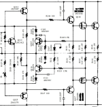
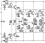
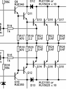
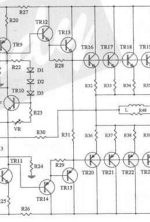
EF3 drive and pre-driver configuration. Which one is better and why?

Hi! I have a question about this.
There is Class A drive. There is Class AB drive, where the emitter resistor of the driver and pre-driver is connected to the output.
There are also drivers where a B-E resistor is used. What are the differences?
Which one is more stable?
Which one provides better sound quality?

Attachments

  • 1.png
    1.png
    113.2 KB · Views: 52
  • 2.png
    2.png
    91.1 KB · Views: 51
  • 3.png
    3.png
    57.7 KB · Views: 54
  • 4.png
    4.png
    80.5 KB · Views: 50
  • 5.png
    5.png
    134.8 KB · Views: 53
  • 6.png
    6.png
    55.6 KB · Views: 51
  • 7.png
    7.png
    25.3 KB · Views: 48
  • 8.png
    8.png
    166.7 KB · Views: 44
Projects by fanatics, for fanatics
Get answers and advice for everyone wanting to learn the art of audio.
Join the Community
507,796
Members
7,888,790
Messages

Filter

Forum Statistics

Threads
406,260
Messages
7,888,790
Members
507,796
Latest member
MAYA MAJIMA