Passive radiator out of phase issue.

I asked this question now and then.but never really got a definite answer. So far it seems to me that passive radiators are effective at their resonance frequency. But outside it they still add a little low end blurry background..muddying the sound. Plus they are moving 180 degrees out of phase or produce sound with 360 degree delay. Would it be safe to say that passive radiators are another way to cheat bass out of smaller volume. Bass is less composed and accurate than from a sealed box

Audio Research SP-11 MK2 Bloom powersupply

Hi,

What can possibly cause this mess?
Can this happen if the MC7812CK is faulty?
Both fuses are blown and the elcos leaked.
I Hope it‘s not a problem upstream in the amp Box.
I think I‘ll first desolder the cables from the power tranny and measure the secondaries. Although I don‘t think it‘s to blame; what do you think?

Thanks for your help
BR
Olaf

Attachments

  • 2E71A140-7DDD-4DB3-8333-B08157A35AA3.jpeg
    2E71A140-7DDD-4DB3-8333-B08157A35AA3.jpeg
    435.1 KB · Views: 261
  • E7CA3C6E-4971-42CE-9502-66E860CE845E.jpeg
    E7CA3C6E-4971-42CE-9502-66E860CE845E.jpeg
    477.6 KB · Views: 275
  • A48771FB-1127-4307-ABBF-80BAF9993239.jpeg
    A48771FB-1127-4307-ABBF-80BAF9993239.jpeg
    450.4 KB · Views: 238

Fake TPA3116D2 IC on amplifier board

Hi everyone,

Wow, I just received a 100W TPA3116D2 Subwoofer amplifier from Aliexpress, hooked it up and found the output was really low.

I took the heatsink and found a nice surprise! A 16 pin chip marked TPA3116D2 but the real thing is 32 pins. What the???

Here is the link to the item I purchased:
https://www.aliexpress.com/item/1005002966206658.html

Has anyone come across this?

Attachments

  • 20220712_225832_resized_1.jpg
    20220712_225832_resized_1.jpg
    308.3 KB · Views: 618
  • 20220712_232644.jpg
    20220712_232644.jpg
    315.1 KB · Views: 867

PS Audio IV preamp

Before i put it on ebay, i thought i will ask here. PS audio preamp, in great shape, working fine, all contacts clean. Have been used as phono preamp mainly. It has both mm and mc inputs, swith on the bottom. Great sounding phono section for vintage audio.
No power supply, it takes 2x24 VAC. I was powering it with regulated 2x28 VDC, and it was absolutely quiet. Cable to plug external supply is provided.
Since i made few standalone tube phono pre, and standalone tube line pre, this PS audio is sitting idle.
Cosmetics 8/10.
Yours for $280 plus $35 s/h in us.

Attachments

  • 20220706_164800.jpg
    20220706_164800.jpg
    435.6 KB · Views: 265
  • 20220706_164812.jpg
    20220706_164812.jpg
    439.5 KB · Views: 256

Germanium Headphone Amplifier from China (using Toshiba 2SB292)

Hello All,

Got this little amp to use with my Sennheiser HD599 headphones.
It came ready built and I just had to provide it with a proper power transformer and a power supply (using an LM337 reg at 20 VDC).
Will provide more details on the actual PSU I am using, in a following post.

The transistors are Toshiba PNP 2SB292 (https://www.web-bcs.com/transistor/tc/2sb/2SB292_cpl.php) and the output transformers are rated for 32Ohm.

Here is the schematic:

1657207454375.png


It seems that the 200kOhm resistor in parallel with the 200kOhm pot sets the bias on the device.
However, I am completely clueless on what to look for to set the right bias for this circuit.
Any help regarding proper bias, will be appreciated !!

Pics of the actual board with its output transformers:
1657207533850.png


1657207583329.png


The amplifier is working OK. Not any noticeable hum or noise.

However, compared to other headphone amps of mine (Lehmann BCL clone, OTL tube amp by Aren van Waarde, Zen-style amp by Tortello and other) it sounds pretty thin. It lacks beef at the lower end of the spectrum.
Otherwise it sounds OK mid-band and higher up.

So, I wonder if there is something to look for, in order to improve things there.

Thanks a lot for reading!
Nick.

Thought experiment on size of output stage....

Without going overkill… what’s the minimum number of output devices needed to run a 4 ohm resistive load close to clipping assuming….
  • +/-110vdc rails unloaded.
  • 1.6kva Toroids ( two 800va units with single 0-80vac taps unloaded)
  • 4x 33,000uF caps (160v)
  • Class AB Config
  • 0.47R emitter resistors with about 6-8mV across each device.
  • Assume adequate heatsinking and MJL4302/4281 Or MJL21193/94 devices…

Single voltage OCL amplifier

I plan to design some single power supply recently. Amplifier suitable for switching power supply.
The voltage range of power supply is DC12 - 60V. Use a single power supply. There is no negative voltage.
BTL structure is adopted. The output has no capacitance.
It is somewhat similar to the tda2005 structure. I think many people now only have some single voltage switching power supplies.
This makes them unable to DIY amplifier. Because dual voltage power supply cannot be purchased in many places.
Traditional transformers weigh a lot.
In fact, all analog amplifiers. CLASS AB。 Can use single power mode.
It can use the floating power supply of quad606.
Or use the BTL mode of tda2005.
https://www.diyaudio.com/community/...-scheme-class-ab-tda2005.388198/#post-7070292
It's easy. So that friends who only have a single power supply do not need to make class D amplifiers with poor performance. For example, tda3116. I think these things are a waste of time. DIY without sound quality has no meaning.

Best option for 9V rechargeable batteries

Hi !
i have taken the decision to try rechargeable batteries as power supply.
I decided this on the basis of a post of a great audio designer using a 9V battery to power a very low noise amp dealing with uV signals.
I need about 9-10V and possibly 4-5000 mAh
I have found Turnigy brand but i have no clue about which would be the best battery solution.
Do you have any suggestion ? anyone using batteries for low V and low A devices with success ?
Thanks a lot indeed. gino

Job listings

I remember as a kid when friends would try to make their job applications look like their current job was fancier than it was. The classic was "food services hostess" for working at a fast food place.
Now job listings are doing the same thing, the titles sound fancy but hidden in the job description is the truth that 99% of the job will be customer service or cashiering.

With great lines like "while empowering you to learn, grow and deliver" which means "we are going to suck the life out of you, while pretending to care"
"As an Inventory Specialist, you will be collaborative and inclusive in helping our customers while being part of a fun, team-oriented retail culture. " = "We are calling the job inventory specialist but you are mostly going to be customer service and we will just blame you for inventory issues"
"....maintaining accurate inventory controls within the store." = "try not to steal too much product and we appreciate it if you snitch on other employees if they steal stuff"
"You will also coach other team members to..." = "you get to bitch at other employees to make you feel better"
" and maintain a neat and clean store" = "as the new guy you get to clean the toilets"
"Understand and use basic selling skills to engage and present solutions" = "customers are going to yell you at"
"Be flexible in performing other duties as assigned" = "someone just threw up on isle 3"

How to stretch mylar and heat treatment!

Hi!

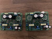
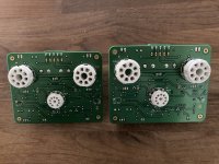
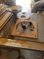
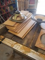
I started to refurbish QUAD ESL63 panels around 1999 and around 2001 it went more serious, a separate workshop was rented together with a friend.
Hostaphan of different thickness in big rolls was purchased and we developed a "perfect coating"... the coating lasted for approx 10 years, so it was not perfect after all. The Hostaphan film stayed stretched!
A lot of testing was done in a not so scientific way, also heat treatment was done with heat gun. But everything can be done slightly better so thats the background of the information in this tread.

This tread is about the properties of polyester film, BO-PET, and you will see that it is not that simple as you may think.
The film has different properties and tensile strength in X and Y direction.
And this is important if you want to stretch the membrane really hard since it will relax slightly over time....
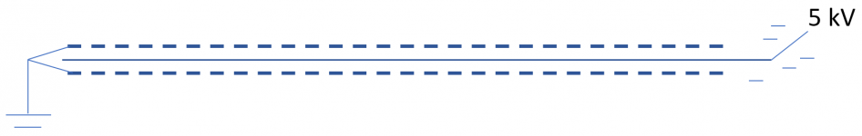
A good stretched membrane will stay almost straight when there is no signal:
1655651903950.png


Too much relaxation means that the film will stick to one side and almost touch the stator:
1655487651947.png

And when the membrane is too relaxed you can get arcing and hiss noise, arcing is producing ozone, and ozone will make the film brittle and it will tear apart and get "rotten". The glue holding the membrane will also decompose or degrade in contact with ozone.

To measure the performance we need to do some testing of the tensile strength and the elongation.
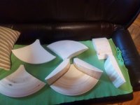
When you apply tensile force to the film it will start to break at the weakest point which usually is where you fixate the film.... Over 20 pieces was tested and 6 of them "worked" by breaking somewhere close to the middle.
Some tape helps out a little bit.

1655487921660.png


Clamping force is crucial.. and many tests has to be done before you get one that breaks where you want it.
I have a MOV movie but could not download it here of the actual "happening" when it breaks...

So here is some snippings..
1655488358745.png


1655488466231.png

Some milliseconds before it breaks..

1655488537568.png

And finally it gives up.

The test jig is moving 50mm/minute and the force is monitored continuously.
There is a difference between X (width) and Y (length) direction but more sample has to be tested with carefully mounting to get better data.
It is also extremely important how you cut the test pieces. Even a small scratch on the surface introduces a force concentration and it will break long before it´s real maximum.

Here is a table with some more or less successful measurements. Test is performed at 21deg C.
1655488916682.png


Nr 2, 3, Is in the longest direction, the winding direction of the roll so to say.
Nr 4, 10, 11, and 12 is in the shortest direction, side to side. The spread of data is as you can see to big to draw any conclusions for now.
Wider pieces will be tested to reduce the influence of irregularities from cutting the film.
Here is a graph:
1655489509598.png


And on 6 samples we can theoretically do a calculation, even though we know that there was some issues when the sample was prepared.
The orange and green curve has a different slope compared to the others, that we can see clearly.

1655489666131.png


This is a good beginning. Or what do you think?
Next step is to measure the influence of heat, you know about the "heat gun" stretch and the "baking" of the film in an oven as we have seen QUAD is doing.
I do not find it but if you know you can post the reference further down, Thank you!
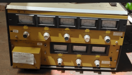
A little teaser for next experiment before bed time...
1655490413080.png

1655491019655.png

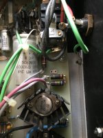
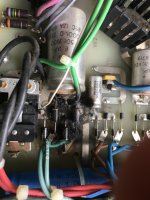
With this test jigg you can adjust the chamber temperature (chamber is not attached in this picture, but you get the point.
Same force diagram is plotted as previous, but here you can adjust temperature within +/- 0,2 deg C. Good enough.
After stretching at a certain force, you heat up the chamber/membrane to a certain very specific temperature where the polyester molecules actually starts to tensioning the diagram even harder! I will explain the physics later on.
And if you exceed this temperature point it will relax instead and then if you heat it even more it will break.... game over.
We need to characterize this better than the attempt above, and also better than the stretch jig i developed >20 years ago, and actually is still working very good by the way!
If you want to make a good long lasting electrostatic speaker, maybe you can learn something here.

Attachments

  • 1655486788762.png
    1655486788762.png
    3.2 KB · Views: 361

FS: E1DA Cosmos ADC grade A

For Sale: E1DA Cosmos ADC
Grade A, Almost new / looks and smells new. Never been disassembled.
Reason for selling: additional funds for audio interface.

Price is 140USD + 18USD shipping.

<ITEM SOLD>

Attachments

  • 288614677_982694128949669_2799685956958903083_n.jpg
    288614677_982694128949669_2799685956958903083_n.jpg
    435.2 KB · Views: 133
  • 288635929_419026336799067_3649694048512660636_n.jpg
    288635929_419026336799067_3649694048512660636_n.jpg
    379.5 KB · Views: 133

Coupling Caps Question

Controversial topic but I'll ask: In your experience, is it worth upgrading coupling caps? I'm debating this for a Bottlehead Moreplay, which sounds good built stock. But maybe we can make it a bit smoother, warmer, etc. sounding ... (?)

First question, what do orange drop caps sound like versus other caps you've compared them to?

From previous personal experience, there's a lot of expensive caps out there that aren't worth the cost or trouble (a lot of these caps are really big and heavy).

Second question: if it's worthwhile in your experience, any recommendations? Auricaps seem like a good bet for their sonics, light weight and small size, for example. I don't mind spending decent money on, say, Vcap Odams or Jupiters (which worked well for series on tweeters), but curious to know your experiences with tube coupling application

FS: Mini-me MM phono preamp

For sale fully populated PCBs (power supply and phono stage). PCBs are 2mm thickness, immersion gold and greater cooper thickness. All resistors are Vishay-Dale RN type and CMF. RIAA capacitors are polystyrene from LCR brand. Coupling capacitors Jantzen Audio Superior Z-Cap. Power transformer from Amplimo model: 2N1357.See attached pictures.
Beautiful sounding phono preamp. Bonus: 4 Tubes 6N16B NOS.
More info and schematic here:
Mini-Me phono preamp

Price reduced: 200 euro, shipping included in EU. PayPal fees included.

IMG_20210602_154753__01_copy_993x777.jpg
IMG_20210602_154802__01_copy_993x892.jpg
IMG_20210602_154815__01_copy_993x655.jpg
IMG_20210602_154829__01_copy_993x544.jpg
IMG_20210602_154640__01_copy_993x1525.jpg
IMG_20210602_154649__01_copy_993x825.jpg
IMG_20210602_154710__01_copy_993x599.jpg

TDA7498 no output

Not DIY but I need some assistance.
I purchased a Lepai LP-7498E with the TDA7498E amplifier board.
When I first connected it and powered it up it worked great.
After turning up the volume to higher levels the protection kicked in and it shut down.
I disconnected the power supply and checked my wiring but didn't notice any issues.
I tried it again and there was no sound output.
I thought perhaps it was because I ran it on a 4 ohm load, so I tried an 8 ohm load and there was still no output.
I swapped the power supply but that didn't work either.
I tried another set of speakers but still no sound output.
I opened up the case and didn't see any visible problems, no popped caps, no burn marks.
What troubleshooting steps should I perform to find the fault?


Any help would be greatly appreciated.

TDA7498E (ETR) strange clipping issue

Hello to everyone,
I'm Fabio, and I'm working on a personal layout of the TDA7498E circuit as described in the Evaluation Board Application Note by ST.
I will try to be brief but all-encompassing to explain you at better all the elements of my situation.

I was a record producer until 2020 with big live experience and a lot of passion in electronics and, latter discovered, in precision mechanics, especially in the audio field.
With my small and new enterprise (since october of the past year) in the south of Italy, I'm preparing a prototype of a special portable amplifier for travelling musicians, and this small class-D amp appeared to be the best choice for the purpose. Please consider that in the small enterprise I'm the only worker and the inventor of the product, and at the moment I'm facing substantially everything (general&administration, project R&D, patenting, CNC lathe and mill machining for any part, circuit designing and building), so I'm facing the last phases of a huge work started four years ago, when I made the first, very simple and basic version of this portable amplifier.
Also, I would ask sorry in advance for my poor english and for my limited competence in electronics because especially in this field I'm totally a self-taught.

The PCB I developed for this project is a single-supply unit powered via Li-ion battery pack with 36V and 10Ah (with BMS inside) and shares rails for auxiliaries voltage regulators, a class-AB power amplifier for the tweeter and finally the TDA7498ETR dedicated section.
The two channels of the TDA7498ETR are connected to a small dual-coil woofer (sell as subwoofer), STEREO mode and gain set to 35.6dB (directly connected to VDDS).
The signal comes from a BOSS preamplifier/compressor unit at the moment. The signal level, checked on the scope, doesn't reach more than 4Vp/p as requested from the TDA7498 data sheet.

Despite my layout is very compliant with the Application Note, starting from:
-decoupling and snubber filter in DUAL solution toward ground as SMT components positioned extremely close to the amp IC;
-same way for any other requested component near the TDA7498E in the input section;
-solid and simmetrical design on the board;
-signal ground isolated by ground and connected without vias directly to negative terminal of the 4700uF bulk capacitor dedicated to the amp (supporting another 2200uF for anything else); 15uH chokes with Isat 6.25A;
-in short: fully compliant to the Application Note;
and the whole board works like a charm (after three different revisions), I'm experiencing a strange clipping issue not discussed elsewhere, the reason why I ask the community help.

Next to the battery pack input connector on the board I provided a multimeter, set as Ammeter, to check the whole quiescent current of the entire circuit and everything's fine for my expectations: less than 200mA.
But what I noticed is a very very bad clipping from the speaker with high transients in the LF part of the signal, when the current measured in the circuit goes over 1A RMS.

Initially I tried different solutions, swapping the 4700uF bulk capacitor with a 10000uF, tried with different chokes and also chokes in parallel (reducing the inductance in the output filter to 7.5uH), changing capacitors in the output filter and also improving main switch cables and removing bleed resistors from the two bulk capacitors on the board, but with no luck.
Most importantly, this kind of clipping seems not due to some sort of built-in protection circuitry because its destructive behaviour (after different trials, the TDA7498ETR explodes).
Before it fatally reached this point, I was looking to the output pins of the IC on the scope, noticing a "strong compression (40-60%) with slight distortion" in the PWM train when my volume reaches the clipping margin.

The strange clip occurs when the total current of the circuit goes beyond 1A RMS... but it happens with transients only.
In example, turning fully counter-clockwise the volume and plucking the bass string, then rising the volume for the sustained note, the Ammeter can give up to 5A and more.

In the reference schematics, you can see the decoupling capacitors of 1uF on the positive input pins. With the floating input the circuit switches on/off very fine, but with the preamplifier connected directly, the sistem starts with a big oscillation under 2Hz, that stabilizes and disappears gradually, so I provided another 1uF in series between the preamplifier signal and the input capacitors, solving the oscillation trouble.
Then, while troubleshooting, I noticed an improvement (more potential headroom on the volume knob before clipping) changing this further decoupling capacitor from 1uF to 100nF before the two positive input pins (so in series with the 1uF decoupling caps described on the reference design).
Clearly lacking a bit of bass frequencies.
As the whole apparatus is intended to be a sealed box, and I was experimenting the functionality of the electronic boards with the speaker mounted into the opened box, I noticed a further improvement (quasi-full potential headroom on the volume knob) simply closing the box.

At this point, my suspects were pointing on the small woofer because its strange Thiele&Small characteristics, having measured a very small linear Xmax... something like 2mm.
My choice went on this specific speaker because I was looking for the best tradeoff between costs and performance for my project. And it was performing quite good, so I decided to work on it as project reference.
Could the solution be in the damping network, that must be redefined due to the electrical characteristic of this particular (abnormal kind of) woofer, commercially known as subwoofer? Clearly I'm expecting the best of its 100+100W output from this small ST monster... after so much work and expense on it.

Still sorry if I dwelt. Hoping and waiting for any hint or suggestion from You and thanking in advance, I wish you a good evening and a nice weekend
Fabio

so I want to use SMD resistors in a through-hole PCB...

I'm thinking of soldering "capacitor leads" cut-off on the each side and then soldering those leads into the PCB. thought?

I'm guessing the added resistance will be very very small.

You may be wondering why I'm doing it.
  1. Well, thin film SMD tolerances can be so much better than equivalent value/wattage resistor for the same price. The temperatures the SMD resistor will be subjected to will within its specs.
  2. I got plenty of time or I can take my time finishing the PCB.

Thanks!

Yuichi A-480FL + Onken bass

I'm starting a new project: the Yuichi A-480 FL for treble and Onken bass. I have had an AudioNote AN-E for 15 years, powered by my SE 300B. Very nice sound, but lacking in dynamics. Some time ago I was following a project from Andre (Hi-End and Hi-Eff loudspeakers system) and the idea came up.
I noticed that no one has tried (or just posted) a two-way variant with a smaller Yuichi horn in this forum. To my knowledge, the Faital HF108R is currently one of the most linear tweeters on the market. It can easily operate from 1kHz, unless high power handling is required. Given that I intend to drive these speakers with my SE 300B amplifier that has a maximum power of 8W / channel, and when cut at 1 kHz, the tweeter will barely receive about 20% of that power. So power handling is not a problem.
In the past, such high cuts (such as 1 kHz) for bass units were virtually impossible. This time I opted for the Beyma SM-115 / N bass unit. You can also find reasons for this decision in the forum from Andre. It can easily go up to 2kHz.
If anyone has experience in this regard, I will be glad to hear your opinion.

Here, I attach a photo of the first step: parts for Yuichi horn, directly from a CNC cutter.

Regards, Sam

Attachments

  • Yuichi A-480FL_CNC(1).jpg
    Yuichi A-480FL_CNC(1).jpg
    170.3 KB · Views: 565

  • Poll Poll
Club Venue DIY Build - B&C

Which design do you prefer for an indoor, multi-purpose application?

  • S18HN DESIGN: horn loaded 18"

    Votes: 1 50.0%
  • S18BN DESIGN: front loaded 18" single cabinet.

    Votes: 1 50.0%

This is my first post here. I am a diy'r for sure. Building cabinets should be in my wheelhouse with the projects I have done in the past. I also have a history (many years prior) as being a sound tech... so I have a fair amount of knowledge of what I am wanting to accomplish...

DETAILS:
I have never owned a horn loaded sub.. I have heard them and not partial to any specific design. I have a club I own that I am building a system for. My goal is (4) total 18" Subs, and 4 full range tops (dual 12" w/ horn)- B&C F2152AN design. The room is large (tall ceilings), however we will be limited to about 300-people per code. Therefore, that system should suffice for most applications.

QUESTIONS:
1.) I believe that I want to stick with B&C based on what I have read. Which sub design should I focus on? I suspect dual 18 cabinets are too heavy to mess with (may periodically move the system). B&C offer a horn loaded 18 -- and then the typical single front mounted enclosure: S18HN & S18BN respectively. What would one offer over the other? I have read tons about the horn loaded design and see several people with strong opinions here against them.
2.) Once dialed in with the design I might want; what amplifiers do you guys recommend for these? It has been nearly 20-years since I have purchased an amp (I was a crown fan then, but realize so much more have hit the market).
3.) Design concerns: I have built other cabinets using Kreg Jig-- I think this will be my method unless there is a sound issue/or if vibrations might back these out etc? Assume with gorilla glue we are good.
4.) DSP: I assume that a DBX Driverack will be sufficient to control the subs (crossover/limiter etc) as well as the full range cabinets above that I plan to build.

That be it for now.. my goal is mostly to get some basic questions answered before digging in further. I have much more reading to do, but hope that the subs above are a good starting point for this DIY project.

DAC suggestions?

I'm going to try to make this as short as possible, but not sure if I'm going to be able to.

I decide to add a headphone amp to my secondary listening system instead of using the headphone jack on my Denon receiver. I thought I would be able to use the Zone 2 output and send digital signals through Denon DAC to the Zone 2. Turns out the Denon won't send anything but analog signals to the Zone 2 outputs. To work around this I am able to connect RCA cables to the Denon from both my TV and Oppo and I am able to listen to Tidal from a secondary Andriod app Mconnect, from the Oppo a BD-103. (Since Oppo n is no longer supported getting the Tidal app to work from the Oppo player doesn't work.)

I bought the Schiit audio Jutunheim 2 amp, which is connected with RCA's to the Zone 2 out on the Denon. So basically I'm using the TV's DAC for TV veiwing, which I'm not sure I care all that much about, and the Oppo DAC for music.

So first of all, I'm not sure I'll ever spend $600 for the Bifrost DAC for example on a secondary system, maybe the Modius, but is it really going to improve on the Oppo DAC?

I've only had this all setup up since yesterday, and it does sound good. Haven't listen to my speakers in here yet, which are Troels Gravenson's Nomex 164's, but from what I can tell the Oppo sounds pretty good like it is over headphones. And turns out I can stream my DNLA stuff from my PC to the Oppo too, instead of the TV's Plex app.

Curious what you guys think.

For Sale Baby Huey Mk2 boards populated-unused

I have for sale a pair of Baby Huey MK2 boards with all parts installed. The boards have never had power applied. I installed parts and set the boards aside over a year ago. So untested.

$75 plus shipping

Attachments

  • 9EBEB3E7-9AFF-4CF8-A1C5-395301F22ED3_1_201_a.jpeg
    9EBEB3E7-9AFF-4CF8-A1C5-395301F22ED3_1_201_a.jpeg
    616.1 KB · Views: 233
  • CA2CED9F-A3C8-4814-AF4D-FA9730261A3D_1_201_a.jpeg
    CA2CED9F-A3C8-4814-AF4D-FA9730261A3D_1_201_a.jpeg
    497.2 KB · Views: 236

Xtant X604 repair help

Need a bit of help with an Xtant x604.
Right rear channel burning resistors

does anyone have a schematic for the amp by chance ? Should component values be the same on all 4 of the output sections ?

r919 and r911 where burnt up ,
97BC5B11-E0D3-4407-963B-1719B390031F.jpeg

The bf422 transistor is showing a non solid ohm reading between the left and right leg , unlike every other bf422 on the board

when I replaced the two resistors they started smoking again , audio was playing with the Burt up resistors , with distorted 1.2v dc offset on the terminal

Help fixing Low Gain Channel on Ampslab C300 amp

Reaching out for some assistance -
I recently built two channels of the Ampslab C300 by Michael Chua. I followed the build guide, schematic and write-up. Used 2N5551/5401 (Q1/Q2?Q3/Q4/Q5/Q6/Q7/Q8/Q9/Q13/Q14) for small signal transistors, 2SC3503e/1381e for the VAS (Q10/Q12) and bias sensing transistor (3503e) (Q11), MJE340/350 for drivers (Q15/Q16) and MJL4281a/4302a for outputs, using 0.47 emitter resistors instead of 0.39 on schematic.
Ironically the first channel, which I spent weeks carefully putting together has a lower gain then the second channel I put together in a weekend? I will call Channel "A" (marked as such in pictures) as the Low Gain channel and Channel "B" the Correct Gain channel. Channel 'A" has about 26 gain and Channel "B" has the correct 31 gain, according to the write-up information.
I have attached two identical schematics - one for each channel with DC voltages using a 40Vdc power supply with a DBT and one for each channel measuring AC voltages to try and trace down the issue. Which I am having trouble finding a smoking gun, so I'm here to ask for assistance. Tested with the same 0.056 input, I get 1.464 on low gain channel and 1.748 on the good channel
The only thing I have changed so far is Q10/Q12 (3502/1381) and matched using a cheap transistor tester so the Hfe and Vf were the same. Changed them because that's where the AC difference showed up first in the schematic as I was tracing voltages (this is my first time to try this process, so I'm sure I have missed a few keys probe points, but hoped what I have provided would give some direction.
I have tested all resistors and diodes (comparing schematic values and comparing to the "good" channel) - everything checked out in spec. or the same as the "good" channel if anything wasn't measuring to spec. I cannot see anything gravely wrong comparing either DC or AC voltages I measured. Triple checked R14/R15 (10k and 330r, respectively) with DMM, compare to working channel and confirm color codes, I believe these resistors set the gain - they both check out within 1%.
When tested with music - both channels had 15mV of bias (after 1 hour of idle warm-up) and offset was <5mV, they both play music without distortion, with the "low" gain channel about 5-6db lower volume (according to my Pre-amp volume control).
Thanks for any help getting this solved. Let me know if I can provide anything additional that will help find the issue.

Attachments

  • Low Channel_DC voltages.jpg
    Low Channel_DC voltages.jpg
    439.4 KB · Views: 101
  • Good Channel_DC voltages.jpg
    Good Channel_DC voltages.jpg
    435.6 KB · Views: 94
  • Low Channel_AC voltages.jpg
    Low Channel_AC voltages.jpg
    438.5 KB · Views: 82
  • Good Channel_AC voltages.jpg
    Good Channel_AC voltages.jpg
    443.1 KB · Views: 98

Fostex 280 doesn't record

Hello,

I recently purchased a Fostex 280 and as I was trying to start recording with it I came across an issue. When it is in recording mode (play + record pressed together) it doesn't record anything from the input, but keeps playing the material that was on the tape before (I am using some pre-used tape to practice for now). The recording timer shows that it's recording but when I play it back the original material on the tape has not been erased and nothing from my input has been recorded.

I have followed the manual and have been trying to figure this out for a while, so any help/guesses will be appreciated. The Fostex is definitely in perfect working condition as it has just been refurbished and looked at.

Many thanks for any ideas in advance!

How to design open baffles with smallest possible baffle size

Hi all,

Please see the attached images.
Some DIY open baffles have large (in terms of width) baffles, but some people are able to manage with smallest baffle width possible.

When i say small, i mean relative to the size of the driver.
How are they able to manage with smallest baffle size (in terms of width) ?? For example, for a 15" driver, how to manage with a baffle width of 17 to 18"

One of the important functions of the baffle is to separate the rear waves and front waves. In that sense, large baffle if preferred. But with small baffles, how is the front and rear waves separation possible ??

And then there is another concept of acoustic off center to reduce the peaks, which is obviously not possible with baffles with small width.

Attachments

  • IMG_20191209_145520.jpg
    IMG_20191209_145520.jpg
    229.4 KB · Views: 1,251
  • IMG_20191209_145536.jpg
    IMG_20191209_145536.jpg
    246.8 KB · Views: 1,661

Strange problem I havent had before.

Built up a pcb.
Tried to insert op amp and op amp legs 1 and 2 bent.
Straightened legs and tried again but op amp wouldnt go into DIL socket.
So tried putting a thin wire into pin 1 and it wouldnt go in.
Some sort of blockage on pin 1 and pin 2.
So had to desolder DIL socket and replace it.
Never had that problem before and they were RS sockets so not cheapest.

Choices for on/off switch for an amplifier: front or back panel? Rocker/toggle/pushbutton?

I'm going to begin a build for an amplifier consisting of an SMPS and some class-D modules. One thing I forgot to buy is a switch to turn the darn thing on and off. The SMPS has a universal 120/230V 50/60Hz input, so the switch should be as well. I thought of a couple of options:
1. Rocker switch on back panel with indicator light on front
2. Illuminated latching pushbutton switch on the front (must not be too difficult to depress!)
3. Good old toggle switch on rear with indicator light on front

This is just a prototype, so I am probably going to build the chassis from wood for now and the switch can't be one of those snap-in types that only work for thin metal panels. Also, cutting a square hole is a total PITA, otherwise I would consider using one of those integrated rocker switch, IEC AC receptacle, and fuse holder things. So I probably need to figure out these other AC power components too... I do have some parts around somewhere that I should be able to use for this purpose for now.

The other thing to think about is inrush and arcing of the switch. Which type is best against this, or how should I protect the switch? Am I over thinking that?

If the amp build works out I will probably move it into a 3U slimline chassis from the DIYaudio Store, and then I can incorporate better quality AC mains connections and fusing, etc. At that time I will need to make a hard decision on the type and location of the power switch. For now I need to get something working and test it all out, including the switch type and location.

Your one or two cents are appreciated. Thanks!

Scanspeak 18W8545K pair in usa

Sold.

In good condition, working and sounding great.
Bought earlier this year but not able to keep up with speaker building interests anymore. Health and age has caught up with me, and need to slow things down.
Shipping is from California 95521. Please let me know your zip code so can check cost.
I’d like to get 160 plus shipping.
Thanks, Don

Attachments

  • 54C75E5D-706C-466F-BAFD-9F0BA2BCEE71.jpeg
    54C75E5D-706C-466F-BAFD-9F0BA2BCEE71.jpeg
    949.1 KB · Views: 122
  • 32C2FB90-DC26-4656-8FFD-F048B7A2B54C.jpeg
    32C2FB90-DC26-4656-8FFD-F048B7A2B54C.jpeg
    665.9 KB · Views: 111

Modifying the Subbu V3 DAC

After discussion with Jean-Paul, the creator of the Subbu DAC V3 (along with Subbu), it was decided that it would be better to have a separate thread to discuss tweaks/modifications from the "standard" BOM build. That is the purpose of this thread. I previously commented on my experience with alternate parts for an early prototype of the V3 DAC. I'll repeat those comments in the next few posts to kick things off.
---Gary

Additional comments added March 10, 2014

After considerable discussion in this thread, there is a consensus developing on a good set of mods and parts that could be the basis for a new BOM. If you don't feel like reading the entire thread, here is a short summary.

C17 - 1uf X7R MLCC Ceramic capacitor (many possible vendors)
C22 - 470uf 6.3v Panasonic SEPC 6SEPC470
C32 - 1uf Wima MKS2 with 2.5mm lead spacing - MKS0B041000F00KSSD
C35 - you should use either C32 or C35, but not both. If you want to experiment with larger values of Wima MKS2 that only come with 5mm lead spacing then use the C35 location instead of C32. You should not use a value >4.7uf or the sound gets worse.
C4 - 1uf Wima MKS2 with 5mm lead spacing - MKS2-1/50/10 or MKS2-1/63/5T or MKS2C041001F00KSSD

Further comments September 1, 2014

The use of 1uf X7R MLCC ceramic for C17 has proven to be controversial. Some people report better sound with the original BOM recommendation of 4.7uf tantalum. Others have recommended bypassing the 1uf X7R with 100nf X7R but androa17 has done good work looking at this and recommends the following to avoid oscillation.
Best: 10uf tantalum + 100nF x7r
Next: 4.7uf tantalum (the original BOM)
3rd best: 1uf X7R

JP has used 1uf X7R for C17 in all his recent builds and reports no problem. In all of my builds I have used 0.22uf COG caps and like the sound and haven't seen any oscillation. So the 1uf recommendation stands.

Nelson's peg-board?

Hi everyone.

I saw an interview with Nelson Pass where he talks about the process of learning to develop the amplifier circuits. He has a good story about making a sort of "box" for changing around components to test new circuits while prototyping new amplifiers.

Has anyone ever seen a circuit for something like that?

It would be cool if Nelson was lurking and could expand on this a little bit.

Thanks for reading my post.

/Dan

Here's a link to that interview section:

Login to view embedded media

How do I size capacitor for off-line LED strip?

I bought a pair of LED "IS" tubes. Fixture takes just one, put it in - lights briefly then goes out. Box says I need an "Instant Start" ballast. No way am I buying that retail...

So I busted one open, looks like a full wave bridge with the 80 count LED string between + and - output, with a 22uf filter cap in parallel. Then a 0.1 uf film cap on one leg of the input, a small inductor on the other.

Looked on line and finally found a pdf where the LED current of one of these tubes was mentioned, 50 mA with 60 max. Using a 100 Ohm series resistor and a variac, I dialed up the voltage until I got 50 mA of AC current - as read by my DMM. This lit the string nicely. The voltage across the string was 93V, so 118-93/0.05 gave 500 Ohms.

Deciding I wanted to use a cap instead of a resistor (as per original), I calculated 5 uF as giving 530 Ohms at 60 Hz. So I replaced the resistor with a 5uF film cap and my current reads significantly more than 50 mA - on the DMM. Fiddling, I ended up with 3.2uF and just OK brightness for a ~50mA DMM reading.

Do I need to use the oscilloscope to look at the current waveform, to ensure I'm putting 50mA RMS through the string? I'd like as much light as I can get, without killing the reliability.

cloning an output transformer

I want to build a transformer with the same characteristics as the hammond 125a, since I cannot buy it and it is very expensive to import it, what calculations do I need to do from the values that the data sheet gives me to be able to have everything to be able to build it?
And if it can't be done, where can I get information on the design of push pull output transformers, since I couldn't find much on the internet
I leave the link of the data sheet
https://www.hammfg.com/electronics/transformers/audio/125a-125e.pdf

Crucial.com PC DRAM

Just a heads-up.

For 23 years I have bought PC DRAM from Crucial.com. Fast, fresh, fits, and priced right.

My new-to-me UltraBook could use another stick, so I ran their Compatibility Tool and ordered it.

12 days ago, and still "processing". My last order in 2018 shipped in 12 hours.

Even WalMart and HomeDepot are shipping faster than this.

Yes, I know there is a supply chain crisis. But Crucial is/was partnered with Micron, the big DRAM plant in Idaho, and selling at higher prices than they could get from their OEM customers. Also Amazon shows stock of this part, for $3 more.

I looked around. A LOT of Crucial customers are saying Crucial took their money and did not deliver, or delivered very slow, or delivered bad goods and avoided refund.
Also, a lot of spam on sites where I know a maker can have off-topic spam removed (ResellerRatings, BBB), but they are not clearing the spam. (Mostly investment advice?) Don't they watch their reputation?
https://www.sitejabber.com/reviews/crucial.com
https://smart.reviews/business/crucial.com
https://forums.hexus.net/general-di...g-direct-crucial-proceed-extreme-caution.html
https://www.resellerratings.com/store/Crucial_Technology

I note that Crucial is really now an arm of Digital River. Which used to be a mediocre shareware payment service, but seems to be something else today. It is notable that half of Crucial.com's pages are excellent, and a few are really slap-dash, like new owners redecorating in a rush. Also the Returns page is Not Found, a very bad sign. The Agreement contract is really long and very favorable to them. (A few reviewers say this was thrown in their face.)

It's 'only' $32, I paid on my Amex (who will side with me), and they have not even billed Amex yet. Maybe it is a misunderstanding or short-staffing.

But I'm in limbo-- will it come? Should I cancel and order at Amazon? ("Ships from Amazon" means they have it in a Bezos building, right?)

Anyway: if you too remember Crucial favorably, watch your step.

  • Locked
GIANT caps Mallory 17500 MFD 22000 17000 GE Sprague -- NH USA

$999 or best offer 😕😀

Attachments

  • IMG_20201209_141611.jpg
    IMG_20201209_141611.jpg
    977.8 KB · Views: 955
  • IMG_20201209_141656.jpg
    IMG_20201209_141656.jpg
    897.3 KB · Views: 958
  • IMG_20201209_141707.jpg
    IMG_20201209_141707.jpg
    795.1 KB · Views: 933
  • IMG_20201209_141721.jpg
    IMG_20201209_141721.jpg
    851.9 KB · Views: 906
  • IMG_20201209_141733.jpg
    IMG_20201209_141733.jpg
    810.7 KB · Views: 849
  • IMG_20201209_141748.jpg
    IMG_20201209_141748.jpg
    848.7 KB · Views: 391
  • IMG_20201209_141800.jpg
    IMG_20201209_141800.jpg
    922 KB · Views: 428

Horn/TL combo

I have been mulling over where to go with my next speaker project. I have come fro pro multiway world and found my way to FR speakers as a result of the forum. I love FR, but they have their limitations. I will be exploring the AN 15 OB tied to woofer as an extension of that, but have also decided to go down the horn road as well. This is mainly due to Lynn's Beyond the Ariel thrad. Having not heard a horn system, I want to something a little cheaper than what he has arrived at, so I will be having to make some choices. ANy suggestions are appreciated, but what i was thinking was either a 12" or 15" pro woofer in a TL/MLTL, TQWT....whatever else of some sort, crossed to either a 1" or 1.4" Horn driver in either a JMLC or Iwata horn. I may try a cheap SEOS platic 12" since it is only $25 each as a first dive, but ulitimately will finish with a pure horn type. If I go Iwata, i may try DIYing them. Otherwise they will come from DiySoundgroup. THe HF drivers I am looking at are the new polymer ones from Faital Pro. THey are new and interesting and have been recommended by a fellow audio enthusiast. SOrry for the ramble. Be forewarned of many more like it😀

A 'Live-in' Bass horn?

Just for laughs, I happen to have acquired 32 x Tannoy 6.1/2" drivers, and my electronics cave up in the roof happens to resemble a horn in my mind - represented by the black hanging rope! The 'mouth' is about 3m wide x 2m high and the throat about 2.5m x 0.6m high which would accommodate the drivers quite nicely in the layout shown on the floor.
As I said, just a bit of cheap fun with few expectations - people's comments please.

20180616_175401.jpg

Enclosure for Eminence Kappa 12A

Hi everyone

I'm new to this forum and hope I can get a little help or building suggestions from you. 🙂
I would like to build a midbass enclosure for my Eminence Kappa 12A. The only requirement is that te driver has to be direct-radiating to produce also some mid sound.
Is it possible to build a horn or should I use a vented enclosure? The size does not matter much, but it should be no more than 100 cm high, 50 cm wide and 40 cm deep. Something like a like a floor standing box maybe?
The mid driver on this box will be a Fostex FD600 to play the mids and highs, or maybe a seperate tweeter for that.

My goal is to use this enclosure from about 80 to at least 650 Hz. I tried a simulation with Hornresp but I'm not there yet.

Thanks for any help in advance!
Jay

Wavecor -- WF182BD04 -- WF152BD04 -- WF152BD02 -- TW030WA07 and 08 tweeters

Wavecor -- WF182BD04 -- WF152BD04 -- WF152BD02 woofers -- TW030WA07 and 08 tweeters

Need gone
make offers.
Everything is half price of retail.


(2) WF152BD02 -- $90/pair shipped -- used, look good except one has soldered terminals. SOLD
(2) WF152BD04 -- $160/pair shipped -- NEW SOLD
(2) WF152BD04 -- $130/pair shipped -- NEW -- small 2 mm cut on surround of one of them, but did not go through -- on thick part of the surround and it's a very shallow cut. Much more noticeable in the close-up pic, than with the eye.SOLD
(4) WF182BD04 -- $185/pair shipped or lower if NE US or close -- NEW Price lowered
Solen.ca: "GrandTotal 411.61$" Not sure if that is CAD or USD or both or if it includes shipping.


----------------------

Combine with WF182 and I will lower prices.

(4) TW030WA07 tweeters -- $75/pair shipped US48 -- PAIR NEW, but domes are green with some having a little black mixed in.
(2) TW030WA08 tweeters -- $75/pair shipped US48 -- Pair USED
(2) TW030WA08 tweeters -- $100/pair shipped US48 -- Pair NEW


An externally hosted image should be here but it was not working when we last tested it.


An externally hosted image should be here but it was not working when we last tested it.


An externally hosted image should be here but it was not working when we last tested it.


An externally hosted image should be here but it was not working when we last tested it.


An externally hosted image should be here but it was not working when we last tested it.


An externally hosted image should be here but it was not working when we last tested it.


An externally hosted image should be here but it was not working when we last tested it.


An externally hosted image should be here but it was not working when we last tested it.

Attachments

  • 101_1622.jpg
    101_1622.jpg
    993.4 KB · Views: 163
  • 101_1625.jpg
    101_1625.jpg
    853.6 KB · Views: 163
  • 101_1628.jpg
    101_1628.jpg
    798.6 KB · Views: 160
  • 101_1629.jpg
    101_1629.jpg
    997.6 KB · Views: 145
  • 101_1630.jpg
    101_1630.jpg
    814.7 KB · Views: 155
  • 101_1635.jpg
    101_1635.jpg
    832 KB · Views: 154
  • 101_1613.jpg
    101_1613.jpg
    1,004.3 KB · Views: 140
  • 101_1614.jpg
    101_1614.jpg
    914.3 KB · Views: 150
  • 101_1615.jpg
    101_1615.jpg
    963.6 KB · Views: 156
  • 101_1616.jpg
    101_1616.jpg
    970.1 KB · Views: 139

Need help for designing preamp with LM4562

Hello all,
I am working on a simple pre amp design with LM4562 and I will appreciate your thoughts and advises on that.
Here are the questions:

1) There is a 47 ohm resistor R16 right at the end of the output stage to isolate it from the cable capacitance.
There is another 47 ohm resistor R15 to limit in-rush current into coupling capacitor C5 which also prevents parasitic capacitance from cabling.
Is there a problem with this figure or in another word should I omit one of them or they are working just fine?

2) The voltage gain I needed for this stage was 2 so I chose 1k ohm for feedback resistors R11 & R14 and the reason for choosing 1k was for noise considerations.
Since the output current of LM4562 is around +/-26mA, I thought there wouldn't be a current issue when generally there is no need for output voltage more than 2 volts to drive any amplifier.
Is it safe to stay with 1k resistors?


Untitled.png

Marantz PM32

Just a few notes on one of these i picked up cheap as dead.

The 1Amp fuse on the a/c transformer board was blown and I checked the DC power supply to find only 1.6Ω across the bridge rectifier! That might have some bearing on it!

I thought it might be one of the 2 transisorts on the output of the power supply, which seem to serve as stabilisers- but no!

It was 2 of the output transistors (darlington) that were shorted collector to base (1.3Ω) I removed the offending and at least had an amp with one channel working.

Ordered 2 new ones 2SB1254 + 2SD1894- and its all up and running. it does have the annoying selector switch issue which is probably caused by age/misuse oxidisation- but i doubt Ill be bothered to desolder it as its a fairly fragile looking device and threads on here are mixed about swapping them out for a 'traditional' type.

The reason the Darlingtons were shorted was probably the cracked solder joints on the sc2240 transistor -

APEX A40 - PCB

Hello guys!

A fresh new APEX A40 PCB layout is here, the RED Devil Edition! In this thread group-buys for the printed circuit boards are arranged.

It's a bipolar BJT based Class-AB amplifier with symmetrical "current feedback" input stage topology and triple emitter follower (TEF) output stage, and it is state of the art of the APEX AB-Class Audio Reference Power Amplifier. Power rating is 100W/8R0 and sound is very pleasant.

APEX A40 - Layout (1).png


APEX A40 -Preview.png


2-min.jpg


Group Buy Information:

The PCBs are 122mmx105mm 2-Layer, 1.6mm FR4, 70micron copper, HASL finish, white silkscreen and red solder mask, as shown in the above pictures.

> The PCBs cost US$10 a piece. (One PCB is for one channel, so for stereo amplifier you need 2PCBs)

> After the GB list is full, each user will be contacted and sent the first invoice for PCB cost, and the rest (including shipping charge, packing and processing charge and PayPal charge) is to be paid before shipping the boards, for which the second invoice will be sent.
International payments are accepted ONLY through PayPal.
Delay between placing the batch order to PCB plant and delivery of the boards to me will be 20-30 days.

Shipping Information:

All PCB will be send to buyer address using Registered Post with tracking number. Delivery date is around 10-30 days depends on country.

List Information:
Please write your diyaudio forum nickname (country) - number of boards.

Group Buy list is open for everyone that wants to get these nice Red Edition Boards for Audio Reference Amplifier APEX A40.

Group Buy - APEX A40 List

ronovar (CROATIA) - 2pcs

Beryllium expanded usage?

Why is there not at least a 6” BE midrange? Is it too brittle? What about beryllium formers? Apparently it had amazing temperature related properties? Is it magnetically inert enough? The BE former could theoretically be literally part of the BE dome or cone (shape and contours and thickness is also important but there’s a company in LA called LA Guage that has extremely impressive abilities to mill it and a thin dome with any thickness and an extremely thin former could probably also be worked out but those are so thin i’m not sure if humans can machine .001mm or whatever it is either way as a number of stiffened foils which must be possible, this could change things what’s going on? I know how lethal it can be but this clip shows some great promise

Login to view embedded media

diytube ST35 clone (Shannon Parks Rev B) for parts or repair. $300

I built this amp in 2002 and it has served me well, but when I removed and replaced some bulging caps recently I damaged the board. It still ohms out but it doesn't light up. I'd like $300 for the whole thing, including some older but still working JJ tubes, and some very nice KLE RCA inputs. The Hammond transformers (272FX Power and 1650F outputs) sell for $375 now on Mouser, so this seems reasonable. But I'm open to offers or to parting it out.

I also have a brand new Alps Blue Velvet 100k pot, diyaudio connection board and knob that I will sell for $20, and a matched quad of JJ El84s, balanced 12AU7 and 12AX7 purchased new from Eurotubes in late February that I will sell for $100 (currently $125 on eurotubes.com, more from other vendors.) Less than 10 hours, so not even broken in.

Attachments

  • IMG_0308.jpeg
    IMG_0308.jpeg
    335.1 KB · Views: 191

Cheap materials for goofing around with speakers.

What 10 bucks gets you at the thrift store.
Three circle templates.
A stack of half inch MDF, great for testing small enclosure designs.
(To me this is the real value as ply is so expensive, hard to move from store, and is unsuitable for goofing off from a cost perspective.)
Four 3.3Ohm 5w.
Two 6.8uF.
Two 5uF.
Twenty four black screws.
Two 10 inch cone woofers. (Good for learning the relationship between T/S and enclosure with real world example.)


Jeremy

Attachments

  • 20220713_152108.jpg
    20220713_152108.jpg
    454.8 KB · Views: 105
  • 20220713_152112.jpg
    20220713_152112.jpg
    510.7 KB · Views: 107

Speaker Drivers (Some Free)

10 Qty - Peerless 8" W8-12T 12PS (Free)

4 Qty - Dayton Audio 10" RS2700S-8 ($5 each)

Buyer pays shipping and paypal.

Local pickup ok.

Vince
Wayne PA, USA

Attachments

  • 20220706_203112_resized.jpg
    20220706_203112_resized.jpg
    174.7 KB · Views: 144
  • 20220706_203138_resized.jpg
    20220706_203138_resized.jpg
    100.9 KB · Views: 141
  • 20220706_203201_resized.jpg
    20220706_203201_resized.jpg
    122.3 KB · Views: 139
  • 20220706_203213_resized.jpg
    20220706_203213_resized.jpg
    206 KB · Views: 138

DML acrylic panels

Saw an interesting video amplifydiy. They compared bamboo and acrylic. The bamboo sounded "richer" smother than acrylic. The acrylic had better top end and more detail. It's going to take alot of trial and error to get these things to become popular or accepted. Some their inexpensive build cost will drive the enthusiasm. For now seems midbsss and midrange is where there at now. Another point he made was the importance of attachment design and quantity and placement of them. Only way to move onis to keep thinking out side of the box. Keep on experimenting, I am have fun with the excitor. Pun intended. Michael
  • Like
Reactions: Makro1

For Sale F5 partial SMD boards, unique power supply board, and most parts

SOLD

ASKING $225 including Continental USA shipping


This is another project I will not build, seeing if another might have an interest in it.

Designed by Jason Leaman and others, this is a super heavy duty implementation of the F5 with a stout CRC or CLC power supply board.

Login to view embedded media
He used some atypical parts, mainly the SOT 227 footprint power mosfets and diode bridges. The boards are NOT UMS mount compatible so you must be provicient at drill and tap of heatsinks.

The signal boards call for mostly MELF resistors, but use standard 3W power resistors. ixys IXTN40P50P and IXFN140N30P huge mosfets are used and mount the boards to the heatsink. Screw connectors can board mount for wire attachment.

dimensions: 260 x 52 x 1.6mm

I include all parts needed for the signal boards except the input jfet J74/k170 pairs, the spade connectors for signal input and signal ground, if you want to use them, and SMD LEDs. The mosfets retail for about $75 per board.

There is a schematic and BOM included, support from Jason has been hard to come by, so I suggest you are an advanced builder, familiar with First Watt amps and power supplies if you take on this project.

The PS board is HUGE (244 x 189 x 1.6mm, NOT UMS mount compatible) and can be set up for CRC or CLC filtering. I will include the Microchip APT40DR160HJ Diode bridges that fit the boards, 16/ea Nichicon 15,000uf 35v capacitors, screw mount connectors, and fuse holders. No resistors, film caps or chokes included. There is no schematic or BOM for the power board. Pretty self explanatory, and he runs over it nicely in the linked video.

So, for less than the cost of the 6 SOT227 parts and the 16 PS capacitors you have a partial kit for an F5 type DIY amp. You supply the other board parts, chassis and chassis components.


IMG_0732.JPGIMG_0733.JPGIMG_0734.JPGIMG_0739.JPGIMG_0740.JPGIMG_0741.JPGIMG_0743.JPGIMG_0744.JPG

my Schurter switches keep breaking

Hey folks, dropping a line to encourage other hobbyists to avoid the Schurter push-push switches. They look great and work wonderfully for a while, but one of mine spontaneously stopped working yesterday and will not latch with the supplied push button.

I have this part in two of my builds:
1241.6821.1120000

https://www.mouser.com/ProductDetail/693-1241.6821.1120

Conversely, if you are into cycling your amps for stress tests or you prefer to hold your finger on the "on" button during the duration of a record, Schurter may be a good choice for you.

For Sale Hammond 274BX power transformer

Greetings,

I have a brand new Hammond 274BX power transformer (box never opened). When ordering the various parts for a tubelab SSE build, I accidentally ordered 2 power transformers. Ships from Canada (SK)


Power Rating (VA) 198
Primary VAC 115 / 125
Primary Frequency 60
A.C. High Voltage Secondary RMS 750V C.T. @ 201ma.
Filament # 1 VAC 5V C.T. @ 3A
Filament # 2 VAC 6.3V C.T. @ 6A
Mounting Type Vertical ("X")

Full specs here:
https://www.hammfg.com/files/parts/pdf/274BX.pdf
asking price: CAD: $120 + shipping (~ CAD $20 to ship within Canada) - CAD $45 to ship to USA.

audio test: 100hz and 1000hz sines with different delays

Hi, diyaudio!

Attached is a flac that plays a 100hz and 1000hz sine 3 times. They all stop at the same time but the 1000hz starts with a delay of 0ms, 1ms, and 2ms.

The levels of 100hz and 1000hz are the same so it can be hard to hear 100hz over 1000hz. Putting the ear near the woofer can help with hearing. Play the clip a few times and try to lock onto the bass tone.

The question is: do the samples sound similar or different?

I am trying to exploit a slower group delay on some of my speakers and this is my first go at a test.

Thanks!!!!

Attachments

Projects by fanatics, for fanatics
Get answers and advice for everyone wanting to learn the art of audio.
Join the Community
507,815
Members
7,889,499
Messages

Filter

Forum Statistics

Threads
406,302
Messages
7,889,499
Members
507,815
Latest member
ezemattaldi