Poindexter's Musical Machine:Tube Power Supply Schematic

I'd be most grateful if anybody here could provide a copy of the 5AR4 power supply schematic for Poindexter's Musical Machine. The web is rife with the sand version, but the "new and improved" schematic seems to be lost to the sands of time (and yes, I've already searched this forum). The Wayback Machine has numerous references to his old site, but many of the schematics are missing - including that one.

And while I'm thinking of it: was there ever a specific schematic for the 6V6/6GK5 version of the MM, or was the builder just supposed to take the 6GK5 stage from the EL34 PP schematic?

Enquiring minds want to know... 😀

Curved vents

Hello,
I have a little question about port calculations.
I wanted to design a subwoofer box for two 12’’ speaker and wanted to make it look like the ks28 from L-acoustics but they use what they call “L-vents” (first picture) that are curved and I don’t know which measure to use for the vent surface in software like winISD.
Do I have to use 340mm or 140mm or something else (second picture) ?

Thanks for your help 🙂

Attachments

  • 39E94431-F766-4DAC-AE40-1E889D7131FA.png
    39E94431-F766-4DAC-AE40-1E889D7131FA.png
    181.2 KB · Views: 457
  • 22A3E546-2ACA-4717-BA7D-57D2A588E870.png
    22A3E546-2ACA-4717-BA7D-57D2A588E870.png
    297.1 KB · Views: 917

Two bags of transistors, one labeled "NPN", the other "PNP" -- but what the heck are they?

I was going through a box of old parts and found two bags of (I think) TO-18 package transistors, one labeled "NPN", the other "PNP".

Looking at what's in the bags, I see the printing on the NPN transistors says SS5928-1 312, with the Motorola logo.

The PNP transistors say SS5929 7224, also with the Motorola logo.

1662163672144.png


I googled around for data sheets or specs and couldn't find anything. These devices must have gone obsolete before the internet happened. I found a 2N5929 and a C5929, but they're nothing like these.

Would anyone happen to know what these are?

Expensive mistake guys please advise.

Hello guys

Long story so I will cut it so you at least feel my pain..18 months ago a purchased 2 bk electronics monoliths and I wasn't overly impressed so after watching many YouTube videos I decided to build 2 subs. So I purchased 2 dayton um18 22 and 2 sa1000 amps.

The boxes I made are

600mm wide
700mm high
700mm deep
External measurements
18mm x2 mdf all round so each panel is
36mm

Furniture foam inside on all sides

When I set it all up they sounded and measured exactly the same as monoliths. I knew this was impossible and I must have an issue. After four exhausting days of fault finding I found a audio enhancement setting on the TV but not in TV settings!! This setting was only visible when I went into the TV through my lap top!! Now the monoliths sound awesome 👌 and I wish I purchased two more at £1400
I'm now £1700 in with the dayton build and they don't sound know where near as good as the bk monoliths! They are punchy and lack extension below 30hz. Infact they only sound good and really loud from 27-40hz But I think they could come good if I add two passive rads to each box

Il be £2400 in by then!! What do you think guys? Are passives the answer? Or new boxes? I was hoping to build monsters but all I've done is put put a monster hole in my bank account!! I'm gutted 😢 😞

I've just ordered a Cambridge 2 channel amp aswell. It's getting out of hand guys! I want to get it right so I just enjoy it instead of obsessing. Big room 4 subs 1 in each corner.

Attachments

  • 20220826_002333.jpg
    20220826_002333.jpg
    266 KB · Views: 169
  • 20220826_002344.jpg
    20220826_002344.jpg
    240.2 KB · Views: 173

75ohm Definitive Technology sub help!

Hello,
I have a pair of Definitive Technology BP2000TLs that use 75ohm 15” subwoofer drivers and 500watt amps. The built in amps have finally died and the place I sent them too for repair said they can’t repair them. My guess is because of the 75ohm load. Anyways, I have a few question

1) I’d really like to fix the original amps. Does anyone know where I might be able to get them repaired. I’d really love to keep them as original as possible since I have always love how these speakers sound!

2) I completely understand that an amp is going to be putting out only a fraction of its rated power at 75ohms, but if I put enough power to them with they still perform. I kinda tested this theory using one of my Onkyo M-501s that are only 150w a channel. At a moderate volume and enough gain they do sound good. Anything beyond that and the amp just doesn’t have output to keep up. I was thinking of maybe using a D-class amp module, and modifying it to fix, but how big would I have to go for it to perform close to the original 500w amp?

3) if #2 is an unreasonable option, then I need to find a reasonably priced 15” 4 or 8ohm sub that will perform well in about 2.8 cft. enclosure with a port that’s 1.5” x 7”x 14”. I don’t have modeling software so any help here would be greatly appreciated!

Thank you in advance!

Faital 10RS350. Suitable for 2 way?

Hi all!

It seems a very interesting driver, so bought a pair of them in the 8ohm version.

Faital Pro 10RS350 10" Bass Speakers - Faital Pro 10RS350 10" speaker for bass guitar. - Faital Pro 10RS350 600 watt 10" bass guitar speaker for all high power bass applications. Faital Pro 10RS350

My plan is to put them in a pair of small vented boxes (around 1cubic feet/30 liters tuned to 40-42Hz)

What I didnt notice is the high Le (1mH) so Im not sure if it would work with a 1" comp driver. Crossed around 1-1,5k

I want to avoid the 3 way option.

Do you think guys it would work?

Thanks!

How do you handle mold/mould in the subwoofer driver?

Hello,

You know, fungi like place without light and subwoofer enclosure is a very good place for this living organism. If we consider that at some sobwoofer we also add textile or metallic grill the environment became even better for then to grow.

It's also important to mention that some guys may live in a very humid country or place witch will make this issue even worse.

Due to the covid situation and having my loudspeakers stored for too long time and found is issue at my drivers, probably it happen not only to me, so, how do you guys handle mold/mould in the subwoofer driver?

Someone knows if they can generate permanent damage or if they can affect the drivers parameter in a significant way? mainly at the spider (driver suspension).

Rust is very common and will affect all the driver soon or later regarding the quality of the coating/paint used in the production process, but it's more visual issue, but mold I'm not much used to see it.

Note.: I made a gig yesterday as it's and the sound quality was not affected yet but today I clean up with lysoform Spray so I hope I was able to kill them for a good period of time and the product don't degrade the spider or the cone due to chemical interaction.

Attachments

  • 20220828_123749.jpg
    20220828_123749.jpg
    181.1 KB · Views: 121
  • 20220828_123755.jpg
    20220828_123755.jpg
    116.4 KB · Views: 138
  • 20220828_123812.jpg
    20220828_123812.jpg
    310.2 KB · Views: 130
  • Screenshot_20220828_183459.png
    Screenshot_20220828_183459.png
    46.6 KB · Views: 124

Measuring speaker stuff starting with Thiele-Small parameters

Hello,

I am packing up and moving.

There are too many speakers, some all original, others recones with OEM parts and others are Frankenstein speakers made with voice coils from one model cones from another model voice coil and frames from another. I have one set of 15 inch Frankenstein JBL’s that are near 2235’s maybe.

What I want to do in this thread is measure speaker stuff starting with Thiele Small parameters of the 15 inch Frankenstein JBL’s.

This is just for fun. I have the time and space plus new to me Audio Precision APx1701 speaker measuring tools.

I am going to start by attaching the Frankenstein drivers to a fiberglass ladder to measure the Thiele Small parameters. I am thinking of using the added weight method as opposed to the known volume box to do the measurements.

Anyone with thoughts to add?

Thanks DT

Selling dinosaurs on eBay I just found a monster

But I'm not buying.
I just bought a NOS Behringer XO from eBay and I was looking at the sellers other items.
Among the stuff for sale were some speakers and this was amongst them. I'd never heard of them but others may have and care to comment on them.
One of the speakers for sale is from Phase Linear
Andromeda 3; a relatively large OB speaker with multiple drivers and multiple orientations.

Attachments

  • 301610092_5326383254147520_9069606120794113189_n.png
    301610092_5326383254147520_9069606120794113189_n.png
    80.9 KB · Views: 437

Infineon MA2304

"Coming soon" on the Infineon site. These look interesting for battery-powered applications.

Product brief:
https://www.infineon.com/cms/en/product/promopages/merus-multilevel-class-d-ma2304xn/

Chip:
https://www.infineon.com/cms/en/pro...grated-class-d-audio-amplifier-ics/ma2304dns/

Eval board:
https://www.infineon.com/cms/en/product/evaluation-boards/eval_audio_ma2304dns/

I stumbled across these while trying to work out whether I wanted to have a play with making something based on the MA12070P using an ESP32 for DSP, however the thing that appeals to me with the MA2304DNS (apart from low quiescent current) is the onboard DSP. Seems it might be a nice way to minimise part count while also allowing for fairly modular / flexible speaker configurations.

There's also a MA2304PNS version that drops the DSP, not sure whether there are any other differences between the two.

I haven't done any sums, but if I'm reading the data sheet correctly, the quoted efficiency improvements seem to be "at typical duty cycle for full range music" and probably wouldn't be quite as impressive if playing sub.

The "PCB as heatsink" approach described in the PDF for the eval board is interesting, but I think I'd want to go for a heatsink for my use case (portable boombox). The size/weight of the amp plus heatsink will be a drop in the ocean compared to the cabinet, driver and battery - and based on the thermals it looks like a heatsink would be useful if I end up with a 4ohm load.

What fuses are appropriate for tube amp supplies?

The maximum sustained power draw for the heater supply in my build is 2.16A, and for the B+ supply it's 90mA. What is an appropriate fuse value for these two? They are already factored above expected power draw by 1.8x. Would 2.25A and 100mA be appropriate?

Then my next question is, should they be slow or fast blow? I assume slow-blow since they are power supply and not line fuses?

For Sale Pair of Lundahl LL1660S/10ma

I'm selling a pair of "open box" Lundahl LL1660S/10ma Tube Amplifier Phase Splitting Interstage Transformer.

They have been wired for ALT B. but I can remove the wires if desired.

They are in very good condition. They have not been powered on. I have bought them by mistake as they don't fit the amp build I'm working on. sigh...

I'm asking $150 plus shipping of a 4lbs. package from 11105

Thanks!

Attachments

  • IMG_9944.jpeg
    IMG_9944.jpeg
    527.9 KB · Views: 122
  • IMG_9945.jpeg
    IMG_9945.jpeg
    679.4 KB · Views: 124

Power input - 2 prong to 3 prong

I'm going to be doing some work on a few vintage items, thought I'd address this as long as I'm opening up the chassis.

They all have 2 prong (live and neutral) power hardwired, no ground. I was thinking about fitting a standard iec inlet and attaching the ground to chassis, as is common practice. Or maybe just hardwire a 3 wire power cable, no iec inlet.

Why would the designers have used 2 prong instead of 3?

Mark Levinson 23.5 bias procedure

I have just finished rebuilding my ML 23.5 and lacking a service manual I am reaching out to anyone who may be familiar with the bias procedure.
Rebuild may be a bit of a stretch since I only replaced the electrolytics and corrected a bad repair job.
Never the less, since other unskilled hands have been in this amp I will feel much better knowing it has at least been biased properly.

Thanks in advance.

Full-range advice for 2W SET

Hi there,
I built a 45 SET amp to replace my Audio Nirvana 300B. The results have been very satisfying so far, using a pair of AN Classic 10 (96 dB/w/m) in AN-designed Monitor cabinets. The only issue I have now is that going from 8W to 2W output, I have to crank the volume at over 3/4 of the scale to get some decent listening level.

So I am thinking about improving the efficiency of my speakers. Following the same principle of simplicity of design that led me to stick to SET + full-range, I have ruled out layouts such as open baffle + servo or loaded horn (too complex to build, too many things can go wrong with my limited equipment).

I have set my eyes on the most efficient, high-end quality drivers I could find, the Lowther DX4 (99.5 dB). Unfortunately, bass reflex seems to be discouraged with this driver. I saw Martin King's ML TL design at http://www.quarter-wave.com/Project04/Project04.html but, after an exchange with Martin, I learned that the passive filter used to balance the highs and lows takes 10dB off the driver, which is a nonstarter.

Another option I contemplated would be building larger enclosures for my AN. I don't know how much I would gain from that, even a couple dBs would help. And of course, I would consider another driver in the >98dB range that is bass-reflex-friendly. I would rather give up some bass extension than overall sound quality and response.

Anybody has any good suggestions, either for the Lowthers or alternatives?

Thanks.
gm

Fullrange speaker with subs

Hi Guys,

This site is such a great resource - particularly for a noob like me🙂 So thanks for that.

I'm starting out in this DIY hobby and the time has come for a pair of single-driver fullrange speakers.

The bass will be taken care of by two Dynaudio 18S subs.

I have two questions:

What is the most punchy fullrange driver? I've had a pair of single-driver speakers from Omega Speaker Systems and while they were transparent and great with jazz and the like, they couldn't boogie.

Are there any fullrange drivers that can?

And more generally: what does the size of the cabinet do, other than bass? Does a driver sound bigger and bolder and punchier in a larger cabinet?


Hope you can help🙂


Mads

A silver + something mixture for planar diaphragm trace repair

Hello,

after 2 years as a second-hand owner of a pair of hifiman arya headphones, the left-side driver has suddenly stopped working.
I was quoted 450 to replace them for a new pair with the stealth magnet (mine were V2), since I am no longer under warranty, which left me a bit disappointed with hifiman's quality. In any case, it left me wondering: is it possible to repair the driver?

Since the problem is not a bad connection with the connectors, and my multimeter shows 0 ohm across the driver terminals, my best guess is that the trace on the diaphragm has been interrupted. A bit of googling around provided some ideas, including silver paint (which I thought sounded good), and soldering a jumper wire between the traces of a nanometer thick diaphragm (which I thought was insane). Going with the silver paint option, I see a potential problem. I believe the traces to be made of aluminum, and trying to paint over said traces would prevent a good conductive contact with the paint, due to the aluminum oxide layer.

So, I was wondering, would it be possible to mix the silver paint with some chemical, e.g., a solvent such as acetone, or an acid/base, that would remove the oxide layer, without damaging the silver, aluminum traces or diaphragm material, and that would also evaporate or react such that it would disappear as the paint dried?

P.S. I am definitely going for the replacement since I don't want a 1000 euro paper-weight, although I am absolutely gutted by the amount (I even promised myself I wouldn't spend money on headphones for the next 5 years when I bought these!).

Sigma Studio issue or is it just me?

I am working on the KABD-4100, its a 3-way setup and I have not been able to get the bridging part to to work. I can get the mid/tweeter to work on J13 fine, but J14 is not outputting anything at all. I have 2 different boards, I have tried both of them. I have tried swapping cables and I have tried the default setup in the demo pack, that doesn't even work!

I read zero coming from the board on the DAC2 output. I am listening to the other ports as I am typing this. I am assuming this is correct? If not what am I missing, if there is any physical things I can do to troubleshoot I'm all eyes! Crossover is at 100hz for the Lo. Oh, I also have the bridging connectors connected, in fact the ONLY sound I have heard is when I connected them and they charged and discharged until it was seated. I also tried unbridging and using the outputs, that didn't seem to work either, though I didn't unsplit the wiring to the sub.

1660363550834.png

Discrete Opamp advice

Hi! Im working on a discrete opamp. Im trying to replace input pairs with something good as the old BC413c/BC415c it has in there.
After some research I have found this TOSHIBA device: HN4C06J
This is to replace the original opamps of an equipment I use a lot and I need to repair. Im making a new PCB layout for them so maybe I use them for another project.

I saw this desing in another threads before with PN100/200 transistors, now obsolete too. the BCs apears to be better though

Any advice?

Thanks!

Attachments

Simple speaker protection board

Hello everyone!

I am looking to create a simple speaker protection board for my diy project. I will be having two LM3886 in parallel with the DC offset regulated by servo. My concern is that on power on - DC will swing between +-35V power supply for the speaker output. I want to remedy that by using a simple time delay circuit that will drive tow Mosfet based relays.

I have +-15V that will be used to power the time delay circuit.

Any input and help will be greatly appreciated!

Here is what I have so far:
sch.PNG

What's easiest, cheap way to change the frequency of a low-pass filter?

My commercial 10" sub has a crossover fixed @ 90hz on both the line and low-level inputs. It's too high and causes the bass to be directional and slightly boomy. I think 50hz would be better. The simplest solution I can think is to put a coil on the driver. I don't mind the 'hole' between 50 and 90hz because there are other speakers in the system to cover the deficit.

Also, I have a theory as to what may be compounding my problem - roll off.

My current system comprises of 7 speakers; 10" inch rear sub, 2 x 6.5" front subs, and 4 x floor-standers with 6.5" woofers. As we all know crossover points are not absolute - there's a slope!

You guys are the ones who know how to operate a slide rule but work it out @ 6dB per octave . . .

Bear with me, I'm formulating this theory as a type . . . there may be holes. Taking 100dB as the listening level, filter the 10" sub @ 50hz and at 100hz it is only 6dB down. 100hz is within the front sub's range, add their contributions, +3db, +3db. Crossed at 120hz, any 6.5" woofer in a 30l cabinet will be only a couple of decibels down at 100hz . There are four of them, +3db.

Is my problem that at 100hz I have 7 drivers making a significant contribution but at 35hz I have only one?

A Simple Low Power 7591 Push Pull Amplifier

I designed and built this amplifier.
Quite a while ago, I mentioned it to one of the members of this Forum.
He was interested in seeing the schematic.
I apologize to him, it took me so long to document it on this forum.

I am not a software geek.
You will have to print the schematics out if you want them.
Then you can rotate them so that they are easier to read.

Warning / Caution: This amplifier has Dangerous Voltages, both at the Mains Power side, and at the B+, tube plates, tube screens, and output transformer primary, etc.

Changing parts for different ones may cause fire, etc.
All building, using, and modifications are at your own risk.
I am not responsible for your actions.

If you see an error in my schematics, please let me know; ask a question, etc.
I am subject to making human errors.

Attachments

  • SCAN0216.jpg
    SCAN0216.jpg
    307 KB · Views: 1,307
  • SCAN0217.jpg
    SCAN0217.jpg
    293.1 KB · Views: 1,208
  • DSCF0630.jpg
    DSCF0630.jpg
    903 KB · Views: 1,230
  • Like
Reactions: DrowningNotWaving

"Park mixer" with Marshall components

Hi everyone,

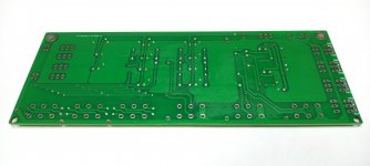
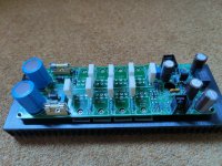
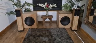
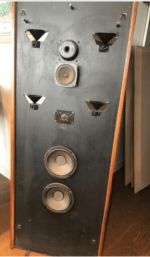
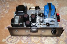
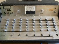
I recently came into ownership of a "Park mixer", as pictured below. This is an 8 channel mixer with no power amplifier. There are no model numbers or any other markings on it, other than a few stickers indicating it went through the hands of a couple Swiss businesses at some point ("Werner Ernst Musique" in Montreaux and "Sacher Music" in Basel, who probably serviced it given that their sticker is on the inside.)

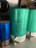
My interest was piqued because of the relationship between Park and Marshall gear from the 1960s and 1970s. (i.e., basically the same, with a few tweaks, formed as a means of circumventing an exclusive distribution deal for Marshall-branded products) As best I can tell, this particular mixer was made around late 1971 or early 1972, since the date code on one of the capacitors is "71 42". I'm guessing it was meant to serve as the head unit to a number of power amplifiers. Sadly, there were no power amps attached to this.

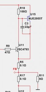
I haven't yet had a chance to sit down and trace out any sort of schematic, but a few things stick out from my preliminary observations:

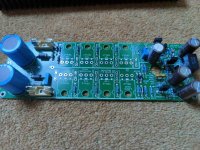
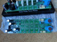
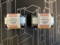
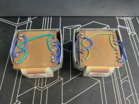
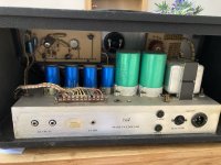
- There are two magnetics: A fairly hefty Partridge power transformer, of unknown secondary voltages, and what looks to be a filter choke with no markings. The choke looks similar to the PT, so I'm guessing it's also from Partridge.
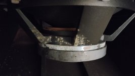
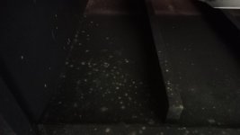
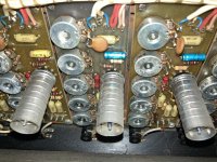
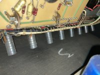
- There's a lot of filtering on this -- two giant 33,000µF @ 40V caps, and four "smaller" can caps. I wasn't able to read all their values, but it looks like at least two are 50+50 @ 450V. At least one of the caps is shot, and has released the magic.
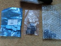
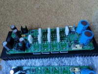
- Each channel seems to have a Marshall-branded ECC82, which I'm guessing are originals. There's one other valve which is a Tungsram, also ECC82, in what I'm guessing is a volume control / channel mixer role.
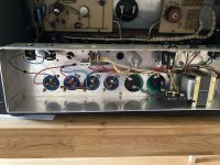
- There are two output jacks, but it's not stereo. They're wired in parallel.
- Looking at each of the channels it looks like some of the components have seen better days. But there's no obvious damage from hack jobs or bad repairs.
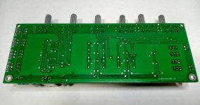
- The "monitor selector" switch has 8 positions; without plugging it in, I believe this will choose the channel that appears on the volt meter. I find it a bit strange that there are two scales on the volt meter, and no obvious way to select the sum of the channels to monitor?

To be honest, I picked this up because the price was right, and I wanted to get a second look at it particularly since it seems like it's a pretty rare piece of kit. I'm not really sure what to do with it, though. I imagine some guitarist would find it quite fun to have (8 "Marshall" pre-amps with an echo effects loop) but would require a bit of investment to fix up and re-cap.

I thought I would post this here, both to see if anyone has any info on this, and also as a place to document this piece of equipment for anyone who finds something similar in the future. After spending days scouring the web I could find absolutely zero mention of anything like it. I could see that Marshall themselves made PAs and some mixers around this time, but nothing quite like this, so it's not just a rebranded Marshall. Perhaps this was a one-off or limited run? Given that it's a "Park" could this be a custom job, branded as such to get around the Rose-Morris distribution deal so they could sell it direct? Park catalogues or any sort of promo material is very scarce, as far as I can tell.

(I find the connection to Montreaux especially interesting, given what was happening around there at the time this was made, but that's just me daydreaming... Who might have played through this? 🙂 )

Attachments

  • IMG_4708.jpeg
    IMG_4708.jpeg
    529.8 KB · Views: 237
  • IMG_4688.jpeg
    IMG_4688.jpeg
    447.8 KB · Views: 179
  • IMG_4694.jpeg
    IMG_4694.jpeg
    309.9 KB · Views: 164
  • IMG_4696.jpeg
    IMG_4696.jpeg
    493 KB · Views: 162
  • IMG_4704.jpeg
    IMG_4704.jpeg
    643.2 KB · Views: 175
  • IMG_4692.jpeg
    IMG_4692.jpeg
    443.4 KB · Views: 177
  • Like
Reactions: justanalogue

Skytroni 902.184 need

Hello, i am not sure if this thread is in proper category if not just move it please.

Is any body selling skytronic 902.184 15" speaker please? Or can anybody tell me if know equivalent of this one? My friend just gave me 2x Jamo D365 but bass drivers been damage before and he bought just one skytronic driver because he couldn't find pair. Just pm me if anybody can hel or answer here. Thanks guys.

A strange project with commercial potential?

I was looking at my desktop system wondering how I could tidy it up, perhaps even eliminate some components, less wires, more desk space etc. It occurred to me, nobody uses CDs or DVDs any more or physically large hard drives. Why not take advantage of the redundant 5.25" drive bays? Install a TPA3116D2 into a CD-ROM chassis. I've no idea how much output power would be generated from the existing 12v power supply but I'm confident it could manage 50w. Maybe you could get fancy and have the 12v supply the sub and the 5v supply the satellites? I don't know, but couple of internal connections to the sound card and you're good to go. 30, 40, 50 bucks to eliminate some clutter and a free-up a plug socket?

Could be a bargain?
Tell the problems.

NAD 208 protection mode

Hi there,

I have bought an NAD 208 a while ago and was quite happy with it. Missed the last bit of transparency and spaciousness and got inspired by the mod replacing the 2 stock NE5532s with LM4562s. So unsoldered the NE5532s and put DIP IC sockets in. Just to be on the safe side I placed new NE5532s (triple check orientation) in there.


Switching it back on the unit stayed in protection mode for 5 seconds, switched to green for another and back to protection mode, and so on: YouTube

I reviewed the service manual and to be honest, the protection circuit description is too much for me to comprehend (quite an newbie in electronics). Seems it measures several different things, so difficult to predict where the problem comes from.

So, I am looking for help to reduce the potential source of problems:
- Is the protection mode at all influenced by the input amplifier board or can I stop worrying that I messed something up on the input board . I double-checked the soldering points and they look really good (my soldering skills are quite ok). But if I know that the cannot be the problem, I can follow the typical "protection mode" related solution paths.

- Is it possible/likely that I fried some neighbouring components on the input board which now cause the problem?

- Might the unit just require adjustment of idle current or CMMR (Common Mode Rejection Ratio)?

Appreciate any guidance on this. I want my amp back!

Thanks,
Christian

Developing a wide adjustment range Tube bench supply

Greetings,

I would like to share an idea of mine for a wide adjustment tube regulated bench power supply. Ive tested it, and it works as expected.

My prototype worked flawlessly from 1.25V up to 350V

This idea uses the LR8 IC because of its low minimum output current requirement spec of 0.3mA typ, as opposed to 3.5mA for the LM317(HV) or 15mA Typ for the TL783. this means you dont have to dissipate as much in the output divider.

The IC cannot provide more than 5mA so an external PNP to increase the current capability is utilized , MJE350 was chosen because it was available, but other 200V 1A class of PNP transistors can be used as well, provided its Beta is large enough.

Instead of a resistor plus zener from the raw B+ to the output, im using the heater for the pass tube fed into a voltage doubler and RC filtered. This ensures that the divider current of 3mA or so is enough to guarantee stability.

Cheers,

V4lve

Attachments

  • LR8 example.jpg
    LR8 example.jpg
    65.4 KB · Views: 294
  • Like
Reactions: TR00 and gerrittube

Stetsom Ex5000Eq DC on speaker terminal

Hi there,
Can anyone assist me with a Stetsom Ex5000Eq amplifier that give out DC on the speaker terminals? The positive terminal has over 40 VDC and the negative has 3.8 VDC. I checked the voltage at the power input stage and there is a voltage drop of over 4 voltes. All of the Power FETs and output FETs give an ok reading during testing.
Any help will be greatly appreciated.

10W Current / transconductance bass amplifier for 60 ohms

To drive the 9 woofers (8 ohm each) in my line array I would like to build a current/transconductance tube amplifier, as previous experience was quite nice. About 10W into 60-70 ohm would be nice.

A first attempt with a pentode push pull output stage was not successful, learned some new things from 6A3summer in this thread https://www.diyaudio.com/forums/tubes-valves/362804-current-drive-valve-amplifier-6.html

There is the possibility of applying current feedback in a global loop, some amplifiers with variable damping factor out there. As I have a 60-70 ohms load and do not need a lot of power, I think an OTL could be an option, but they do not always have a high output impedance.

So, curious about your ideas! Thanks, erik

Screws frozen in plastic case

Should be a fairly simple fix on this, with the right knowledge that I don't have at this point.

I have a piece of audio equipment with a sturdy plastic housing, but 2 of the screws on the bottom seem frozen and will not turn
even after soaking for a while with WD40. The screws are not stripped and I have a screw driver that is the right size but somehow
these screws will not budge as if they have had glue included when they were originally tightened in.
Other screws around them came out, but with some difficulty.

Any suggestions on how to loosen things up and get them turning out for me ? Would PB blaster be too corrosive or damaging to drip inside
the case from soaking the screws in that ? Only thing I can think of at this point is progressively stronger penetrants.

thanks for any ideas

Value error of new versus old caps

I have many years of experience with precision measurement of poly caps and they tend to measure very close to spec. Lately I have been doing some amplifier board work and notice that whereas old (80s) electrolytic caps tend to measure OVER the rated capacitance, new units tend to measure UNDER rated capacitance. For measuring, I have both the DE-5000 and the Atlas ESR70. This happens even when ESR for the older cap is lower than the ESR of the newer cap.

Is this common knowledge?

DIY (MM) Phono Stage - Passive RIAA Equalization/Rumble Filter

The turntables have a great come back and the industry shows new models year by year.

Also many new music productions are released also in vinyl added the offer of many older reproductions in better edition (remastered 180gr records, etc.)

Those made me try to design my new phono preamplifier for moving magnet (MM) cartridges. Please, are there any suggestions on this circuit or any other proposals?

Attachments

  • 1. PHONO PREAMPLIFIER.png
    1. PHONO PREAMPLIFIER.png
    153.6 KB · Views: 2,404
  • 2. PSU PHONO.png
    2. PSU PHONO.png
    169.6 KB · Views: 1,345
  • Like
Reactions: aroS3

Transformers MIC and Phono

I read an application note on Sowter where someone used a step up transformer for a Moving Magnet Cartridge as well as Moving Coil (where it is almost a must).

What would the detriments be if I had a unit made that took a 47k ohm primary and stepped it up to 235k (1:5 turns ratio)? The active circuitry would produce 25 dB of gain instead of 40 after RIAA to lower the noise floor.

For moving coil mode, I could add taps that step it up even higher.

Edcor makes small signal transformers that look to me as if they can perform this task. Given that they are unshielded, hum I suppose could be an issue if they are not enclosed in a chassis. One reason I like Edcor is they are made in the US, not China or Europe (high shipping costs).

Pmp 6000

I have a Berringer PMP 6000 new to all this I have 4 passive speakers 8 ohm cabs. 3 monitors. Thing Barely runs the two mains one hooked up to the back A-b speaker on connections. I also have a 3000 W Rockville power amp to channel. what’s the best way to hook all of the stuff up and have some power with a little headroom? when I say barely runs it means the main slider and a channel slider is almost maxed to get any punch at all?

Attachments

  • 987DE76C-00D1-46FD-B051-BF88A5EB7478.png
    987DE76C-00D1-46FD-B051-BF88A5EB7478.png
    454.9 KB · Views: 88
  • 59708736-D139-412C-B383-FB0B69F9CBD8.png
    59708736-D139-412C-B383-FB0B69F9CBD8.png
    105.6 KB · Views: 96

MAOP 11 cabinet plans

I’m looking to build a speaker with the maop 11. I have a cabinet builder ready to build whatever cabinet I want. what I am looking for is the best overall sound. I’m not necessarily worried about bass output as I can add subs. Bookshelf or floor standard, either one is fine. so, if I have a box that can do reasonable bass output as well, that’s fantastic, but if I’m just looking for overall clarity/sound stage, not necessarily worried about low bass, what would you all recommend? If you have a recommendation, please also include a link to the box plan you recommend. I appreciate any help upfront. I am new to the DIY process.

For Sale MiniDSP- DDRC-22D or DDRC-22DA, 2x4HD, nanoDIGI B

For sale.

All needs to go.

1. MiniDSP Dirac Live box

Both DDRC-22D
and DDRC-22DA in 1 box.

Dirac Live® correction DSP with SPDIF/AES-EBU/Toslink interface inputs.

User serviceable outputs (analog or digital)

https://www.minidsp.com/products/dirac-series/product-line-summary

DB567A4B-0772-432C-B581-35E693497ADB.jpeg


6FF76C00-7ED8-49B0-A10F-C93D6F426D33.jpeg


I’ll include both output interfaces so you can choose: digital output or analog output. Just needs removal of a couple of screws and disconnecting/connecting the desired output interface, so that it can be converted to analog outputs. Or digital outputs.

Currently in digital out mode; for connection to external DAC.

But I can convert it into a DAC for you:
https://www.minidsp.com/images/documents/Product Brief-DDRC-22DA.pdf

0755A05F-9A34-444B-8652-281A1C52595F.jpeg


I can confirm it works, as I’ve used both the analog out, and digital out version.

price lowered

$450 USD


2. miniDSP nanoDigi DSP

SOLD

Asking $250 USD

3. FOUR FiiO D03K stereo
(8 channels of D/A conversion)
SOLD
$80USD

4.MiniDSP 2x4 HD
SOLD

5.https://www.minidsp.com/products/accessories/wi-dg
SOLD
$40 USD

Shipping ex-Australia.
Paywize or PayPal (you pay extra 3%)

Edit: found more stuff to sell
Edit 2: … thanks for your interest: photos and prices added.
Edit 3: prefer to sell nanoDIGI and DACs together. Please make offer.
Edit 4: another price drop and condensed for things sold and shipped.
Edit 5: REMOVED photos of ALL items no longer for sale.

Attachments

  • 7D9B07A8-725D-403D-835D-2DC7CEA2C5D0.jpeg
    7D9B07A8-725D-403D-835D-2DC7CEA2C5D0.jpeg
    237.9 KB · Views: 146

For Sale For sale - John Broskie CCA, PS-18 power supply, switching PCBs, Antek AS-1T200

Sold!


Time to admit I have more stuff than I have space for, or time to build.

Up for sale is an almost fully populated cathode coupled line stage kit by Mr. Broskie. These are currently out of stock on his website. I was setting it up for 12 volt tubes, then ended up building the NuTube preamplifer instead. Don't need this anymore.

I have $250 in receipts for everything seen below.

I let the smoke out of the PS-18 board with a slip. Itll arrive with spare parts, and everything it shipped with.

The CCA will also arrive with everything it shipped with, which is every option you can check on Broskie's website when buying one.

Antek AS-1T200 also included.

$150 + shipping to the lower 48 only please. No, I won't go lower.

20220827_190858.jpg
20220827_190909.jpg
20220827_190922.jpg
20220827_190934.jpg
20220827_190943.jpg


20220827_190845.jpg

QSC GP-218?

I have recently purchased a larger QSC system that came with a set of QSC's MD-S218 cabinets for subs. Nice sub...but no handles, and sized entirely wrong for packing in the truck, and I bet I need more cabinets to run the system outdoors anyway. My initial though was to swap the MD-S218 cabinets for GP218 cabinets, but I haven't found any used GP218's for sale anywhere, at least not enough of them that I can get shipped here. I'm beginning to wonder about the possibility of making a clone/substitute of the GP218 with my CNC machine & how to get the box design & driver choice correct to play well with the rest of the system.

Anyone tackled a project like that before? Tips? Thoughts? Suggestions? Anyone know if the MD cabinet is the same driver as the GP218?

Thanks,
Todd

M&K KX10BK SubWoofer Switch On Mute

Hi finally got my M&K KX10BK SubWoofer fixed of sorts, sounds great again no thanks to the hours of messing about with fake transistor, the only problem I have now is how does the circuit mute the speaker as I get a nice thump every time days gone by a relay was used, I have noticed with no speaker connected the DC offset which ideally should be 0 Volt but Its about .235 volt there is no means to adjust this with an offset preset, it appears it may be that I need all match pairs of transistors but I struggled enough getting non fake ones as I was.
I just wondered if anyone else had similar problems.

McIntosh MC60

I found a pair of these for sale. Dirty, corroded, and untested, the seller wants $4000 for the pair.

In addition to cleaning, it would need re-capping, new sockets(?), new tubes,... All of which I can do myself.

Are transformer failures very common with these? Any other concerns with this model?

It looks like clean, known working units sell for $4k/pr, maybe $5k/pr if they've been rebuilt/serviced.

What would be a reasonable offer given the condition and untested?


McIntosh MC60.jpg

Son of Ampzilla turn on pulse

I have a Son of Ampzilla that I acquired in 2014. I got great help on this forum back then for a channel drop problem. The amp has been working great until recently.

I now get a pretty severe turn on pulse, followed by a slight hum that is of equal volume in both channels. The hum is more pronounced with the inputs disconnected. The turn on pulse is the same if the inputs are connected or disconnected. The pulse has been getting worse and I am starting to be concerned for my speakers. The amp still appear to work fine as far as the sound goes.

I am thinking something is getting funky in the power supply since both channels are equally affected. Anyone run into this issue before?

Pro Audio: Kustom Profile Series 1 P.A. for Sale

Up for grabs is a Kustom Profile Series 1 P.A.
100W (50W per Channel)
5 Total Input Channels for Mic/Instruments
One Playback Channel w/ RCA In
One Recording Channel w/ RCA out
Two KPS-LS100T Gig Monitors (no stands)
Two 10ft 1/4" Monitor Cables
Asking $200 or best offer.
Will ship to Domestic US for additional fee (UPS estimate is $80)
Each component of the system weighs 15.8 lbs with an approximate shipping weight of 50 lbs. Local pickup available in Southwest-Central Oklahoma to nix shipping costs.
System has been tested, and performs very well.

IMG_20220822_080124206.jpg
IMG_20220822_080142136.jpg
IMG_20220822_080034833.jpg

  • Locked
For Sale Pass Labs Aleph 3 clone, class A

Up for collection only and from Milton Keynes is my Aleph 3 clone .

In excellent cosmetic condition and perfect working order.

I’m looking for what I paid for it which was £650 ( for established members )
I may also consider a swap for a quality preamp but it must have remote control.

It has a ding on the very back right hand cooling fin ( not me )

Please message me if interested

It’s a beast of an amp so you may struggle to fit it in a Hifi rack .

30w class A

Built by Joe Henry

Dimensions
50cm Wide
40cm Deep
22cm High

Speaker protection
Dual toroidal transformers
Dual 50 amp bridge rectifiers
Dual power supplies
160,000uf Elna capacitors
Double-sided thick gilded PCB boards
Power Soft start circuit
Blue LED on/off switch
Input differential Transistors using the new US FU9210
DC blocker
Precise matching mosfets
Supply rail fusing
XLR balanced inputs
RCA inputs
Audio grade binding posts

SPECIFICATIONS
Gain 20 dB
Freq. Response - 0.5 dB at 2 Hz, 100 KHz
Power Output 30 watts/ch 8 ohms
60 watts/ch 4 ohms
60 watts/ch 2 ohms
Maximum Output 23 volts, 8 amps
Distortion (1KHz) 0.2% @ 30 watts, 8 ohms
1% @ 60 watts, 4 ohms
1% @ 60 watts, 2 ohms
Input Impedance 23 Kohm
Damping factor 100
Crosstalk > -80 dB 20-20 KHz
CEE74CFD-AA20-4A62-8F26-5667070CC72B.jpeg
B6285EFF-6BFD-4720-9959-B3313B222442.jpeg
B165BE71-F723-4ED3-B7DB-030F870B4806.jpeg
C59A41D5-5246-4A89-B42E-224273E270FC.jpeg
D4499870-BAC0-4181-A1BC-A232AFF290CA.jpeg
07FEED7D-34AC-4712-8968-C6FCE272392F.jpeg
11AD2A17-6D60-48DE-B844-CEC6800AE9BE.jpeg
0ABE034F-40B9-4C6A-AAAD-C09AC376BC78.jpeg
BF796766-4F15-4C6F-9584-26F9F0EC7AC2.jpeg
FC636319-E9DA-4E7C-86D8-C59EA381F46D.jpeg
DEB9B1E9-8AF3-43D0-A6AD-1410B1D7BCE5.jpeg

Advise needed for DC coupling capacitors

Hello all,
I was just wondering on "settling time after switch-on" of DC blocking capacitors of preamplifiers. Some designs have say 1uf , some 10uf and some have electrolyte 220uf or 470uf. Perhaps in case of 470uf we would have longer settling time. Is using 470uf ok? Or we would face a problem? And if the answer is yes what would be the problem of long settling time? (Although some famous designs use large value bi-polar capacitors. )
Thanks.

External power supply connectors

I almost completed a single ended KT88 amp. It worked fine, but I did not finish it because it weighs 30kg. I put all high voltage tube amps high up on a shelf to keep them away from children. The shelf is only rated for 30kg so I can't put it up there. Even if I wanted to put it up there I don't have the strength to safely lift it that high. So the amp is just sitting there and I can't use it. The only options is to build a cage around it or to split it into 2 chassis. I am choosing the later.

It is definitely not ideal, but occasionally I read some of you do this. What do you use for the connection between them. The easiest option I came across is the MC4 connectors meant for solar panel. They are rated from 1500V DC 30A. I wonder if anyone have experience using them?

My other option is to use octal CMC type tube socket (the bottom can be plugged into any tube socket) which would require a bit more work. My other other option is to make both sides unremovable without opening up the chassis,

On tne commercial side, I see manufacturers use aerospace connectors for this. The highest rating I found are at 600V. Not unusable, but I would prefer the rating to be 800V or higher.

Waffle grills attached with magnets

Finished these speakers tonight and thought I’d share the grills since I haven’t seen this done before.

Used #10 spax screws because they have a large flat top to mate up with the neo magnets I got from Amazon (1/2” x 3mm). Black magnets to hide better.

7DDECD61-AB96-422D-8E36-AB3BBA963FB3.jpeg9A502D92-6F13-4FD9-9852-CBD344543E6B.jpegBE33D9E7-E479-412C-8346-D004945E8707.jpeg6C008AA1-B368-4FE4-AB49-C2343F68D083.jpeg3296BB15-EDCE-45C4-AFC3-DCC0B6C54A2D.jpeg

Bonus tip: put some blue painters tape under your driver mounting area and it will come back out easily in the future. Did this under the WG as well.

99EEE99B-A48D-49CC-A3F5-4D427B69FAF7.jpeg

Homemade alexya tone corrector preamplifier

I started with the design, the back of the preamplifier, now it won't necessarily stay like that, if you have other mounting options, they are welcome,,,,,,,

1. 4 inputs by selecting CD, TAPE, RADIO, etc

2. A direct entry

3. A balanced XLR input

4. and two exits

http://www.vaneijndhoven.net/jos/relaixedpassive/

Attachments

  • BACK PREAMPLIFIER.png
    BACK PREAMPLIFIER.png
    27.9 KB · Views: 123
  • BACK PREAMPLIFIER.rar
    BACK PREAMPLIFIER.rar
    3.1 KB · Views: 88
  • 005.jpg
    005.jpg
    317.2 KB · Views: 98
  • 006 (1).jpg
    006 (1).jpg
    357 KB · Views: 89
  • 006.jpg
    006.jpg
    357 KB · Views: 83
  • PTR MARIAN.jpg
    PTR MARIAN.jpg
    383.4 KB · Views: 85
  • 003 (1).jpg
    003 (1).jpg
    180.5 KB · Views: 86
  • 003.jpg
    003.jpg
    272.5 KB · Views: 85
  • 004.jpg
    004.jpg
    170.2 KB · Views: 81
  • 007.jpg
    007.jpg
    209.5 KB · Views: 95

Beginner bench supply

I am going through the process of getting/finding my first adjustable and current limiting power supply. I have a linear fixed regulated 13Vdc supply and some SMPS blocks (18V etc) but I'm finding testing circuit ideas difficult without some controllable power (other than a lightbulb). I have a scope already so it's time to add a current limiting power supply at the cheaper end of the scale.

My requirements are simple - control at low power before moving up. To that end my requirements are:
  • Small - it needs to sit on a shelf next to the little DSO.
  • 1-60Vdc allows me to test low voltage including
  • floating power - this allows me to use a virtual ground as ±30 or ground as +60V or -60V.
  • Output enable/disable switch
  • Separate current and voltage dials.
Bonus points
  • programmable power
  • additional power ports
  • USB SCPI port

I've actually now ordered two and received one already. The reason for this is that the Multicomp can only limit down to 250mA and that registered after it had shipped. I get the second tomorrow after which I will (highly likely) RMA the Multicomp Pro. However this gives a great opportunity todo some research with device in hand and pass on that knowledge for any other beginners. My money so this is not sponsored.

The supplies are:
  • Multicomp Pro MP710081 (a rebadged Manson NTP-6561)
  • Tenma 72-8340A

Horn resp Front loaded horn

Hi

I have a few questions regarding the placement of a driver in a front-loaded horn.

In horn resp, it sims it as the driver firing directly into the mouth of the horn i have attached an example pic.

However I often see in front-loaded horns that the driver is placed on the side of the horn and fires into the side/throat I assume this is in order to fit the driver in a reasonably sized box (WSX Plans attached as an example, as the plans show the driver shoots into the side of the horn and has a slight gap which I assume is based on compression ratio. Does the throat make it as if the driver is shooting directly into the horn, if so what is the best way to design this so it works as expected?

I'm wondering if anyone has any advice/knowledge on how best to do this without affecting the response of the horn.

Hope this makes sense.

I am fairly new to horn/cabinet design so any help or advice is appreciated.

TIA
Ollie

1661849460814.png

1661849622763.png

AB100 near completed

Decided I need to clear some projects and unfortunately this one made the short list of one's to sell. Hopefully it can give someone some pleasure and not be sat in a box.

Nearly completed in that both channels nearly fully populated. All components are there I believe apart from the self wind output inductors. Also may need fuses. Not sure the ones I have are correct
KOA BPR, Yageo MFR, Elna Silmic , Vishay in the build.

One heatsink is drilled and tapped. Will include ceramic insulators.

Asking £100

Attachments

  • IMG20220821082630.jpg
    IMG20220821082630.jpg
    671.2 KB · Views: 140
  • IMG20220821082606.jpg
    IMG20220821082606.jpg
    620.1 KB · Views: 130
  • IMG20220821082600.jpg
    IMG20220821082600.jpg
    478.6 KB · Views: 131
  • IMG20220821082541.jpg
    IMG20220821082541.jpg
    607.7 KB · Views: 119
  • IMG20220821082535.jpg
    IMG20220821082535.jpg
    687.2 KB · Views: 126
  • IMG20220821082533.jpg
    IMG20220821082533.jpg
    565.6 KB · Views: 130

Horn/Waveguide Dispersion Question

Howdy folks. Forgive me if this is an absurd line of reasoning, but I have a question regarding the manner in which sound travels in a horn / waveguide speaker. I have been watching a bunch of YouTube videos from Joseph Crowe, as well as reading some of his blog posts, and I have noticed that he pays a great deal of attention to how the sound travels along the horn even after it wraps around to the other side of it. This is obvious just by looking at his designs, which I have attached. At this time I do not understand the math involved with the shapes he comes up with, but I do know the shape of the back of the horn is just a continuation of the formula that dictates the shape of the front of the horn, which if followed further seems to start to spiral?

Mr. Crowe seems interested in minimizing diffraction, as well as deadening the sound that makes it to the backside of the horn (back waves?). In the picture featuring his cat you can see that he has put acoustic dampening into the concavity in the back of the horn, which is meant to attenuate the sound energy.

Mr. Crowe seems to think this rear radiation is substantial enough to warrant this sort of design, and I am wondering if you could take this in a different direction.

If you had the mathematical know how, could you hypothetically guide this backward travelling sound energy into a shape that disperses the sound in a manner that mimics the sound of a dipole or bipole speaker? I know the time alignment would be different, but just considering the listener's perception, I am wondering if something pleasing to the ear could be achieved. Sort of an "ambient tweeter" effect, like in the Smell E/III

I am new to audio, and very ignorant to the math behind speaker design, so forgive me if this is an obviously dumb idea. Thank you!

Attachments

  • unnamed_1.jpg
    unnamed_1.jpg
    49.3 KB · Views: 135
  • 1135-003_large.jpeg
    1135-003_large.jpeg
    16.8 KB · Views: 153

Question about calculating values for a 2nd order PLLXO

On the TLS.org site for calculating component values of 2nd order pllxo, the formula prescribes that C1 and C2 as well as R1 and R2 differ by a factor of 10. What is important about that factor? There are myriad combinations of values of those four components that will give a specific identical (or very nearly so) F3. Why is it defined that the two sections differ by a value of 10? What happens if C1 and C2 (and proportionately, R1 and R2) differ by a value of, say, 8?

Thanks to anyone who can shed light on this.

Peace,
Tom E
Projects by fanatics, for fanatics
Get answers and advice for everyone wanting to learn the art of audio.
Join the Community
507,758
Members
7,887,186
Messages

Filter

Forum Statistics

Threads
406,170
Messages
7,887,186
Members
507,758
Latest member
Cindy