Cyrus two - non polar cap

Hi,
Last night i horridly found out that c43 (470uF 6v DC feedback filter cap ?) has gone bad. (Swollen and cracked on both channels). I need to replace them both of course.
However, i do not have such easy access to non polar caps where i live.
I am wondering if it would be too horrible to replace it with a polarized capacitor (the neg pole being connected to the 1k resistor).
Can it harm anything or Deteriorate the sound quality?
Will it effect the life span of the cap ?

P.S.
There are quite a few sources for the service manual on the net, some of them specify that this cap is polar, some don't (meaning its non polar).

Thanks -
Liquias

Attachments

  • cyrus1pwr.gif
    cyrus1pwr.gif
    22.8 KB · Views: 911

New drivers in old B&O cabinet

Hey Guys,

I've bought a pair of B&O Type K speakers. They are in fine condition and I love the way they look.

The cabinet is particle board and approx. 100 liters. There is no brazing.

I am looking for advice to make them into a sleeper speaker - you know, kind of like an old car that looks old on the outside, but is high-performance on the inside.

I listen to a lot of electronic and ambient music so bass is important. Hopefully down to 30hz. I favor musicality over neutrality.

I have a couple of ideas to get there, but welcome any other suggestions:

1: Put a pair of EMS LB12MK2 in each and call it a day. I don't know if they will work in that cabinet. I'll be changing the front and back baffle so I can make any kind of port or passive radiator. I've found a pair of the LB12EX (the field coil version) for a good price, and could also contemplate those, but at €1800,- for the pair I'm basically over my limit.

2: Putting two Seas A26 in series or parallel in each speaker, plus a tweeter or a small fullrange driver from e.g. Markaudio etc. (I've already received great advice on this config. from this thread: https://www.diyaudio.com/community/threads/seas-a26-devore-style-build.369124/page-18#post-7151096 )

3: A pair of Scanspeak 30W/4558T00 that I have laying around with a fullrange driver. Crossover at somewhere between 200-600 hz.

4: A 12" ferrite fullrange driver from Audio Nirvana that is on sale here in Denmark.

5: And finally, a 12"-15" coaxial driver and a really careful (active?) crossover.

With the multiway options above I'm not completely adverse to going active.

Are there some knowledgeable people out there who can point me in the right direction? I'm a novice, so managing the demand for really nice sound with my limited skill is probably the real challenge here. Which - even though I've posted this the Multiway forum - makes me somewhat partial to a fullrange solution.

Anyway, hope you will chime in. I'll post some pics of the Type K speakers below. And let my quickly add: I'll save the original drivers and crossover and front and back baffle so the speakers can be brought back to original again🙂

Kind regards
Mads

Quotes being edited

It is going to be a fun build. I have built myref gainclone in the past too. Though switched to commercial alternatives later, cause my wife did not appreciate my metalworking skills. This time around I will get a proper enclosure made. Still assessing whether I should do an integrated version with just a potentiometer and a mechanical input selection or build another LDR or differed preamp. If I use SMPS I think it will be noisier than linear supply (and not an ideal option for an integrated, all-in-one option) however not too sure.


Like Reply
Report


richbandit

Member​

2017-08-12 6:18 am Chepstow, UK

I didn't post this? - not me!!

These were posted in the Wolverine Build Thread. Seems @Voxonline was able to edit a quote of @richbandit.

Reducing voltage post regulation

I got an lm317 337 regs feeding a +-24v buffer. And from the same reg id like to power an opamp at +-15v. So i need a circuit to drop 7 volts. Initially i had passive shunt reg in mind but could there be more elegant way to achieve my goal? The input voltage is already fixed so i dont need another voltage reg per say. Maybe a cap multiplier thats configured for 7v difference will be better for the opamp rail's pssr? But the shunt is a constant current draw which i understand would keep the 317 337 happy.

What are your thoughts?

Sub Grill and Front Bracing Questions

I am building some relatively large PA subs and I am hoping for some guidance on how to make the front bracing removable to be able to access the driver as well as how to get a grill on this sub and still looking "pro". Keep in mind that the enclosure has not been glued up yet. I am using 3/4" plywood and the nominal mouth opening is 15 3/8" x 21".

Below is my current plan on how to make the bracing removeable.

Removeable Bracing.png


The sides of the braces that can be accessed from the outside of the cabinet will have 2 threaded inserts side by side, everything will be countersunk so everything still fits flush. The top of the vertical braces are a bigger question mark for me. Current idea is to have 1/2" Neodymium magnets countersunk in the top of the braces and in the face of the mouth, should allow for relatively easy removal of the front brace. However I am not sure the "connection" between the 2 magnet pairs will be strong enough for the brace.

Does anyone have any ideas on how to design a better removeable front brace? How about thoughts on this idea? Concerns?

Below is my plan for the grill.

Grill.png


My current plan is to make a 3/8" rabbet cut with a router at the depth of the grill so everything is flush. I then plan on countersinking 3/8" Neo magnets in the locations specified on the picture. I am worried that they might rattle in the corners and off the center of the bracing in the mouth.

Anyone have any better ideas? I also have toyed with the idea of countersinking a pair of 1/2" magnets on the actual corners of the mouth and in the center of each side. Countersinking them below the actual depth of the grill. Any hints or other ideas on how to accomplish these objectives would be greatly appreciated!

By the way, does anyone know a good place where I can purchase a metal grill for this specific purpose (and have it cut to size)?

Dayton Audio 15" Ultimax Subwoofer

SOLD

Price new - $355
My Price - $200

An absolute monster sub, in good condition. Functionally perfect, cosmetically very good. I used duratex as the finishing coat.

I prefer local pickup (I'm in Denver, CO). Since this was a kit, I don't have a box for it. If I were to ship it, it would be very expensive to build out a box and buy all the packing materials, probably over $200 additional cost (buyer pays).

For payment, I take Zelle, Venmo, Paypal, Money Order or Check (after it clears).

IMG_0018.jpeg
IMG_0019.jpeg
IMG_0020.jpeg
IMG_0021.jpeg
IMG_0022.jpeg

MTX Thunder 4250D

Anyone know the value of this diode ?

Or the part number

D601

Also the part numbers for the drivers as seen in pic 2
Or have some pics of the board o noticed some resistors missing also.


This is how I received the amp

Attachments

  • E4E93073-9A11-4BB0-BEFF-5FD771104D5D.jpeg
    E4E93073-9A11-4BB0-BEFF-5FD771104D5D.jpeg
    598.6 KB · Views: 109
  • DD3F2DA9-5984-4D7B-AF33-A8DDE625A473.jpeg
    DD3F2DA9-5984-4D7B-AF33-A8DDE625A473.jpeg
    650.6 KB · Views: 95
  • AF68854A-6161-4B38-B95E-DC30E9F39369.jpeg
    AF68854A-6161-4B38-B95E-DC30E9F39369.jpeg
    644.8 KB · Views: 94

For Sale FS: Jupiter Copper Capacitors 15uf

New Price is $1440 for the pair.

My Price - $650 for the pair.

SOLD


Jupiter copper foil capacitors - 15uF

Functionally perfect and cosmetically excellent. I accept Paypal, Venmo, Zelle or cashiers check. I'm in Denver, buyer pays shipping.

Pics below:

Attachments

  • IMG_1829.jpeg
    IMG_1829.jpeg
    280.7 KB · Views: 117
  • IMG_1830.jpeg
    IMG_1830.jpeg
    299.2 KB · Views: 118
  • IMG_1831.jpeg
    IMG_1831.jpeg
    282.3 KB · Views: 99
  • IMG_1832.jpeg
    IMG_1832.jpeg
    255.9 KB · Views: 125

Floating XLR cables

I entered the world of church sound guy and video streamer a few months ago (I got drafted but wanted to help). I 'm a volunteer. I have an IT background and built an FM receiver from scratch a long time ago but have much to learn about mixers, streaming, and more,

Roughly 150 people attend. Rural, no rock band, lots of hard wood and sheet rock surfaces, overhead HVAC, etc. The sound booth is at the back of the church. Microphones and speakers are about 75' of away as the wiring goes.

Someone in earlier days switched from wired microphones to wireless microphones and left a bundle of XLR cables in place. That bundle contains 20+ individual cables; one of which is still used for one remaining wired mic. In this bundle are also four cables that connect to powered speakers (two stage monitors and two wall mounted speakers).

All of the cables that are not used are not connected to anything at either end. They float. Should I be grounding these unused cables at one end? If so, suggestions for an easy and/or inexpensive way to do this? There is no way to pull out these cables from the bundle without a lot of (painful maybe) work.

Thank you.

John

ADC + DAC (I2S) ground planes PCB

This post is related to a build I've been mostly discussing (learning from) with @abraxalito, but it goes into a more general question that pushed me to create a new thread about it. Obviously not a new topic either, but it's really puzzling me.

As part of a project, I'm bringing together an ADC chip (AK5381) and a stack of multibit DACs (TDA1387) via an Arduino M4 I2S ports (Teensy4). All powered on batteries with independent voltage regulators or current sinks. Problem is, on the breadboard I occasionally got unbearable avalanches of noise out of the DAC. At first it would run ok, but after a few seconds the avalanche of cracking noise would start and continue until turned off. The noise was related to the DAC, without it the ADC would give clean readings on the MCU. I experience the same problem with another DAC (AK4384). I tried different voltage regulators and nothing really worked. Pretty much discarded everything I could and I'm very suspicious of a ground problem, or lack of proper ground.

The overall circuit is pretty complex but I'm putting it into a PCB in Eagle and got to the point of creating ground planes for all three sections: analog, digital and shared. The Mickey Mouse model in my mind, without much experience and research about the subject.

The ADC has independent analog and digital pins, but the DAC doesn't. Should the DAC ideally be located and grounded around the shared area, where the ADC's AGND and DGND meet? Are there any guidelines or important techniques to consider, such as use of ferrites or inductors, other than decoupling capacitors at power supplies? These are things I'm wondering about, mostly hunted by the ghost of manufacturing board prototypes that will welcome me with furious noise accompanied by the question "why didn't you ask before".

For Sale Keces DC-116 Dual-output Regulated Power Supply

This is an excellent dual output (12V/3A + 12V/3A) power supply that will make your audio gear sing. Check the review I've linked below for a full description of its capabilities.

Excellent condition and has spent most of its life sitting in storage (<50 hours use).

Review: https://positive-feedback.com/Issue65/keces.htm

Price: AUD $400
Item Condition: Excellent
Shipping Options: Pickup available (Sydney, Australia). Shipping at agreed cost.
Payment Method: Paypal

Attachments

  • PXL_20210405_071623831.MP.jpg
    PXL_20210405_071623831.MP.jpg
    262.6 KB · Views: 128
  • PXL_20210405_071604345.MP.jpg
    PXL_20210405_071604345.MP.jpg
    149.3 KB · Views: 123

Is it possible to damage your hearing playing acoustic guitar?

I've been playing guitar a little more than usual this past year or so. I chord with my left hand, so the top of the guitar - sound hole etc - is about 12" from my right ear when I play seated, which, is how I play. The right one has been behaving funny lately. First thing I noticed was "the beeper in the microwave seems like it's dying". Maybe it is, it's old. The other thing that had me aghast was the acoustic guitar actually sounded like it's distorted. Really. Enough so I started poking around in it thinking some brace inside had loosened up and was buzzing. Picking up the next guitar, it did the exact same thing. These are nylon string guitars...

Well I got out the ol USB ear-o-scope and nothing deep in there looks to be grossly amiss - like a wax chunk abutting up against the eardrum. My sound level meter says I can hit around 90 (max hold) at that distance (A weighted) when strumming hard, which I sometimes do. I dont play every day and for sure short of an hour each time.

The tinnitus is definitely more prevalent in the right ear too. After playing several songs, it feels a little taxed, or heavy, compared to the left. Is it possible I'm doing my right ear in, at my age of 65, by playing an acoustic guitar occasionally?

I went off and bought myself a Yamaha "Silent" guitar also with nylon strings, but I dont have it yet. Hopefully it's a nice instrument and will cut down my SPL exposure during practicing.

Laser Pickup Failure Modes ?

During my career, I have replaced hundreds of defective laser pickups.
Whilst some have emitted no laser light, the vast majority do emit light but will not work correctly.
In these cases, the cdp may load TOC, but then not play, or will load TOC and play, but mistrack easily on various discs or when the player is bumped.
Examination of the HF waveform reveals dirty signal in some cases, but not all.
Any references to a definative study of what causes laser pickup assy failure ?

Eric.

71A preamp

Hello,
A while back I build a Salas 6v6 preamp, and combined it with a low gain version of Hypex Ncore power amp, and I really love it. I like this hybrid combination despite the purists from either camp.

This time I have a pair of 71a tubes, a pair of Neurochrome Modulus-86 boards, a Vicor PSU a bunch of DC-DC modules, and a gutted old Stromberg Carlson chassis. I plan to make an integrated amp out of it all. I don't need more than 3-6db gain from the 71a's, so I figure a simple resistor loaded tube stage should be fine. I'm not really an expert on calculating load lines and all the details, but I cobbled together this incredibly basic input stage from operating points mentioned here, here, and here. I have an isolated 190V on hand from the DC-DC convertors, although I can trim the voltage down a bit.
  1. Does this basic schematic look ok, with 7K?
  2. What would the output impedance of the preamp stage be?
  3. Also, Ale has the grid biased to -10V, but the data sheet mentions -27V, as does the other DIYA thread I referenced. Could someone clarify what is optimum?
For the filaments I have 24VDC on hand, but can trim down to 15V, and of course can use whatever resistor value I need. I don't plan to use CC on the filaments at this time, maybe later if I need to. I have some ripple attenuators that I plan to use on the filaments. I used them on the heaters on the 6V6 with great success, getting the noise down below -100db.

Thanks!

Attachments

  • 71a_v1.jpg
    71a_v1.jpg
    18.8 KB · Views: 748
  • IMG_2011.jpg
    IMG_2011.jpg
    630.9 KB · Views: 645

For Sale FS: Vcap ODAM Capacitors - 10uf, 4uf, 2.2uf

SOLD


Prices:

10uF - $140 each (new). My price - $85 each
4uF - $123 each (new). My price - $75 each
2.2uF - $111 each (new). My price - $70 each

I accept Paypal, Venmo, Zelle or cashiers check. I'm in Denver, buyer pays shipping.

Attachments

  • IMG_1726.jpeg
    IMG_1726.jpeg
    377 KB · Views: 190
  • IMG_1729.jpeg
    IMG_1729.jpeg
    424.5 KB · Views: 173
  • IMG_1730.jpeg
    IMG_1730.jpeg
    362.2 KB · Views: 160
  • IMG_1727.jpeg
    IMG_1727.jpeg
    357.7 KB · Views: 174

Marantz CD-67 produces scratchy noises

After more than 20 years, my faithful companion is now making noises on some CDs.
These scratching noises (see attachment mp3) are only present on the analog output, everything is OK on the optical SPDIF.

What could be the reason, has anyone had a similar experience?
Any guesses as to possible causes?

Attachments

  • DSC00158a.jpg
    DSC00158a.jpg
    268 KB · Views: 313
  • DSC00161a.jpg
    DSC00161a.jpg
    531.4 KB · Views: 511
  • mp3.zip
    mp3.zip
    2 MB · Views: 110

The sound of an earthquake - in stereo!

This morning we had a 6.7 magnitude earthquake 120 km south of us out in the Pacific. It shook and shook and shook. One of the longest quakes I've ever felt, anywhere.
Out in the barn we have a seismograph and it picked up the shaking just great. But what if you could convert that shaking into an audio file and listen to it? Well I did.

Here it is sped up about 40X. The right channel is my seismograph, the left channel is from 20 km on the other side of the volcano. Sounds good on headphones or big speakers.

Attachments

New aluminum-cone Purifi drivers

https://purifi-audio.com/ptt6-5x04-naa-08/
I was thinking to myself all along that an aluminum cone would make the Purifi woofers even better. Problem is, it's saddled with the same issue that most other aluminum cones have - a relatively low breakup frequency. I'm sure HiFiCompass is going to do a test on these at some point, but I expect to see the high-order sub-harmonic HD amplification from that breakup manifest in a significant way. You already see it in the manufacturer's distortion curves for HD2 and HD3.

When I was reading the audioXpress article, I was saying out loud "please don't let it be a vanilla cone"...feels like the Purifi team just mailed it in, here. Oh well.

EDIT: Taking back some of the comments above. Comparing to other modern aluminum cone drivers, really the performance is not lacking in any way... still wish they had come out with some brand new technology though.

Is this a good port tune for a 3" driver in a small enclosure?

I'm designing a small enclosure (100 in^3) and putting 2 3" drivers in it. I tuned them in WinISD and was wondering if this is a good tune. I have the Transfer Function Magnitude graph, Air velocity graph, and cone excursion, along with the box size, tuning frequency, and port size. The drivers are Dayton Audio DMA80-4 3

Attachments

  • Cone excursion .png
    Cone excursion .png
    26.1 KB · Views: 89
  • Air velocity.png
    Air velocity.png
    28.1 KB · Views: 94
  • TFM tune.png
    TFM tune.png
    25.3 KB · Views: 85

Audio Note CD transport / DAC questions

I've acquired some Audio Note pieces and was curious if they're anything significant worth holding onto.

The CD transport model is CDT-Zero and the D/A is DAC-One 1X. There are no transport control buttons on the CDT. Everything has to be controlled via IR remote which is rather strange.

A quick listen shows the pair to be very analog sounding, sort of like that TDA1541 NOS sort of vibe, but more vivid and with better, tighter low end. Vocals are more forward and present with a well defined sound stage I believe they use a pair of 6111WA dual triodes in the output buffer stages, which explains the improved sound with it warming up, playing for a while. Compared to my RME Pro2 FSR running in NOS mode, it has some striking similarities. Mind you, the RME is no slouch and holds its own compared to some $5k DACs I've heard. The Audio Note DAC is a decent sounding piece of gear. Not sure what to do with it having a few other comparable DACs and transports.

Attachments

  • 20221012_231539.jpg
    20221012_231539.jpg
    409.7 KB · Views: 198
  • 20221012_231633.jpg
    20221012_231633.jpg
    425 KB · Views: 210
  • 20221012_231556.jpg
    20221012_231556.jpg
    415.2 KB · Views: 213

Alpair 5.3 best crossover / stop jumping

Hello audio loving people,

I have a question that I could not easily find (correct me if I am wrong) about the following:

I have a Mark Audio Alpair 5.3 full range driver 90 - 25.000 Hz - other specs are not relevant I believe, if so please ask.

I have tried building a High Pass crossover @ 100 Hz to try and prevent the driver from almost blowing up during the lower frequencies at higher volume.
(driver almost jumps out of its frame). This did not work. Should I try a 200 or 400 Hz High pass? Or am I missing something else?

Cabinet is sealed if that matters. (yes I am an amateur).

Hi and thanks to all of you for some great reads

Hello people, my name is Nick, I live in the UK and want to thank you all! I've spent countless hours reading over posts and replies form you guys and there really is no end to the useful information and helpful people on this site!

Great job to everyone who contributes.

To start me off i was wanting a way to list what equipment i have in my profile or in any other way before posting anything. Is this possible?

Cheers

port noise vs driver/baffle leak ?

im driving a 2x12 ROAR HARD and 200cm2(each) for 210 cm and 800-1000cm2(each) for 120cm. the drivers are horizontally opposed right at the 1/4 wave sections Vmax/exit). its wierd(the swishy sound).

cant attach image for a day or two(it would likely help the diagnosis instead of this ambigouis, "guess for me"😀) but will these sound distinctivley unique to rule one out over the other..

Meniscus Audio 2022 DIY Get-Together : SEPT 23-24 Grand Rapids, MI

I thought I would create a thread for this 2-day event that will be taking place in late September here in Michigan. More info here:
https://meniscusaudio.com/event/meniscus-css-audio-get-together-2022-day-1/
https://meniscusaudio.com/event/meniscus-css-audio-get-together-2022-day-2/

On Friday night I will be demoing the Linux audio software that I use for crossover DSP processing and to stream audio to various playback clients. This is the same software I used to run my system at the recent PE sponsored Speaker design Competition, but this time with multiple wireless clients. The demo system consists of a pair of 2-way Raspberry-Pi controlled active monitors plus subwoofer. The software runs on a laptop computer under Ubuntu and pushes a Gstreamer pipeline to each client in the system. Configuration is very flexible and easy to change via text files. Please stop by and ask me about it if you are interested. It will probably be set up in the shop area.

I think Javad will be demo-ing his latest pair of speakers that night as well in the listening room. I don't have complete details on that, so maybe someone can fill them in for me in a follow up post. Thanks and hope to see you there.

MOTU Ultralite Mk5 - can't get it to work 10 channels (ALSA alt-set 3)

I probe the available modes of operation via ALSA as so:
Code:
cat  /proc/asound/UltraLitemk5/stream0
MOTU UltraLite-mk5 at usb-0000:03:00.3-2.1, high speed : USB Audio

Playback:
  Status: Stop
  Interface 1
    Altset 1
    Format: S24_3LE
    Channels: 22
    Endpoint: 0x02 (2 OUT) (ASYNC)
    Rates: 44100, 48000
    Data packet interval: 125 us
    Bits: 24
    Sync Endpoint: 0x83 (3 IN)
    Sync EP Interface: 2
    Sync EP Altset: 1
    Implicit Feedback Mode: Yes
  Interface 1
    Altset 2
    Format: S24_3LE
    Channels: 18
    Endpoint: 0x02 (2 OUT) (ASYNC)
    Rates: 88200, 96000
    Data packet interval: 125 us
    Bits: 24
    Sync Endpoint: 0x83 (3 IN)
    Sync EP Interface: 2
    Sync EP Altset: 2
    Implicit Feedback Mode: Yes
  Interface 1
    Altset 3
    Format: S24_3LE
    Channels: 10
    Endpoint: 0x02 (2 OUT) (ASYNC)
    Rates: 176400, 192000
    Data packet interval: 125 us
    Bits: 24
    Channel map: FL FR FC LFE RL RR FLC FRC RC SL
    Sync Endpoint: 0x83 (3 IN)
    Sync EP Interface: 2
    Sync EP Altset: 3
    Implicit Feedback Mode: Yes
I cannot get either Altset 2 or Altset 3 to work properly. I also noticed that some of the available PCMs for the device are invalid, e.g. surround71... etc.

If I use phughw I can get 8 channels of 192k Hz audio to play. That's not even shown as part of the stream0 info, so I am a little confused. I can also get 22 channels of output as long as I use either 44.1k or 48k rate.

I have a Gstreamer testing app for audio interfaces, so that I can see more about how they might be used via that platform. It basically tries all channel counts up to 22 to see if the interface will accept the format. For example, here I am running it with 192k and plughw and you can see that it can accept 2, 3, 4, 6, or 8 channels of audio, but not 10. Weird.

Code:
~/system_control/scripts/ALSAINFO.sh plughw:CARD=UltraLitemk5,DEV=0 192000 S24LE

ALSAINFO.sh written by Charlie Laub, version 2.1, July 2021

testing ALSA device: plughw:CARD=UltraLitemk5,DEV=0
Using a sample rate of 192000 Hz
probing the device with an audio format of S24LE

ALSA info about plughw:CARD=UltraLitemk5,DEV=0 :
plughw:CARD=UltraLitemk5,DEV=0:     UltraLite-mk5, USB Audio

ALSA information about this device:
------------------------------------------------

ACCESS:  MMAP_INTERLEAVED MMAP_NONINTERLEAVED MMAP_COMPLEX RW_INTERLEAVED RW_NONINTERLEAVED
FORMAT:  S8 U8 S16_LE S16_BE U16_LE U16_BE S24_LE S24_BE U24_LE U24_BE S32_LE S32_BE U32_LE U32_BE FLOAT_LE FLOAT_BE FLOAT64_LE FLOAT64_BE MU_LAW A_LAW IMA_ADPCM S20_LE S20_BE U20_LE U20_BE S24_3LE S24_3BE U24_3LE U24_3BE S20_3LE S20_3BE U20_3LE U20_3BE S18_3LE S18_3BE U18_3LE U18_3BE
SUBFORMAT:  STD
SAMPLE_BITS: [4 64]
FRAME_BITS: [4 640000]
CHANNELS: [1 10000]
RATE: [4000 4294967295]
PERIOD_TIME: [125 1000000]
PERIOD_SIZE: (0 4294967295]
PERIOD_BYTES: (0 4294967295]
PERIODS: (0 4294967295]
BUFFER_TIME: [1 4294967295]
BUFFER_SIZE: [1 4294967295]
BUFFER_BYTES: [1 4294967295]
TICK_TIME: ALL

------------------------------------------------


Probing device 'plughw:CARD=UltraLitemk5,DEV=0' using Gstreamer...

This device will accept an audio stream consisting of 2 channels of audio in the S24LE format
The bitmask for this mode is: 0x0000000000000003
   channel 0 is used in this mode. Its channel mask is: 0x1
   channel 1 is used in this mode. Its channel mask is: 0x2

This device will accept an audio stream consisting of 3 channels of audio in the S24LE format
The bitmask for this mode is: 0x000000000000000b
   channel 0 is used in this mode. Its channel mask is: 0x1
   channel 1 is used in this mode. Its channel mask is: 0x2
   channel 3 is used in this mode. Its channel mask is: 0x8

This device will accept an audio stream consisting of 4 channels of audio in the S24LE format
The bitmask for this mode is: 0x0000000000000033
   channel 0 is used in this mode. Its channel mask is: 0x1
   channel 1 is used in this mode. Its channel mask is: 0x2
   channel 4 is used in this mode. Its channel mask is: 0x10
   channel 5 is used in this mode. Its channel mask is: 0x20

WARNING: the number of channels was changed to: 2
This device will accept an audio stream consisting of 2 channels of audio in the S24LE format
The bitmask for this mode is: 0x0000000000000003
   channel 0 is used in this mode. Its channel mask is: 0x1
   channel 1 is used in this mode. Its channel mask is: 0x2

This device will accept an audio stream consisting of 6 channels of audio in the S24LE format
The bitmask for this mode is: 0x000000000000003f
   channel 0 is used in this mode. Its channel mask is: 0x1
   channel 1 is used in this mode. Its channel mask is: 0x2
   channel 2 is used in this mode. Its channel mask is: 0x4
   channel 3 is used in this mode. Its channel mask is: 0x8
   channel 4 is used in this mode. Its channel mask is: 0x10
   channel 5 is used in this mode. Its channel mask is: 0x20

WARNING: the number of channels was changed to: 2
This device will accept an audio stream consisting of 2 channels of audio in the S24LE format
The bitmask for this mode is: 0x0000000000000003
   channel 0 is used in this mode. Its channel mask is: 0x1
   channel 1 is used in this mode. Its channel mask is: 0x2

This device will accept an audio stream consisting of 8 channels of audio in the S24LE format
The bitmask for this mode is: 0x0000000000000c3f
   channel 0 is used in this mode. Its channel mask is: 0x1
   channel 1 is used in this mode. Its channel mask is: 0x2
   channel 2 is used in this mode. Its channel mask is: 0x4
   channel 3 is used in this mode. Its channel mask is: 0x8
   channel 4 is used in this mode. Its channel mask is: 0x10
   channel 5 is used in this mode. Its channel mask is: 0x20
   channel 10 is used in this mode. Its channel mask is: 0x400
   channel 11 is used in this mode. Its channel mask is: 0x800

I have also tried probing the interface using speaker-test. It "works" with 10 channels but there is a noticable delay of about 1.5 seconds so that when channel N is producing audio speaker-test has already moved on to the next channel. So I am not convinced it is legit. When I attempted 18 channels at 88.2k (Altset 2)
the channel count counted up to 18 and then there was a seg fault. I could get audio output from my headphones when it was on channel 11 and 12, so it seemed to be wrapping around the available channels.
Code:
speaker-test -D plughw:CARD=UltraLitemk5,DEV=0 -c 18 -r 88200 -f S32LE

speaker-test 1.2.6

Playback device is plughw:CARD=UltraLitemk5,DEV=0
Stream parameters are 88200Hz, S16_LE, 18 channels
Using 16 octaves of pink noise
Rate set to 88200Hz (requested 88200Hz)
Buffer size range from 24 to 176400
Period size range from 12 to 88200
Using max buffer size 176400
Periods = 4
was set period_size = 44100
was set buffer_size = 176400
 0 - Front Left
 1 - Front Right
 2 - Rear Left
 3 - Rear Right
 4 - Center
 5 - LFE
 6 - Side Left
 7 - Side Right
 8 - Channel 9
 9 - Channel 10
 10 - Channel 11
 11 - Channel 12
 12 - Channel 13
 13 - Channel 14
 14 - Channel 15
 15 - Channel 16
Segmentation fault (core dumped)

The interface has 10 TRS balanced output on back, plus optical in out which can carry 8 channels, 2 spdif coax, and 2 MIDI for a total of 22 channels. I really would only like to be able to use the interface on all 10 analog outputs at the advertised rate of 192k.

When I use pulseaudio the format used is 8 channels of 96k, although I did not make any attempts at tailoring pulseaudio for the interface.

Any ideas on what I could try here, or should I just blame this on a poorly developed Linux driver?

A little help needed by some fellow diyAudio Member from Slovakia (purchase at bazos.sk)

Dear fellow diyAudio comrade from Slovakia,

I'd like to do a purchase at bazos.sk, but due to not having a slovakian or czech telephone number (which is required there to identify) I cannot get the vendor's email adress and so I cannot contact him. Will you help me out please and get the email adress for me?

Best regards, Gerd

Has anyone powered their HiFi speakers with PA amplifiers successfully?

Just wondering if anyone here has tried this with low efficiency speakers. I have a pair of 6ft tall magnepan planar speakers that i restored that are very inefficient but people say that having huge power is the key to get the best out of them some people have audio amps with 500w rms per channel (megabucks) and being on a budget far below that pa seemed like a good idea-are there any amp brands that are particualarly good with resolution, detail etc?

Wolfram 2400

Good evening

I have this wolfram 2400 here. It had damaged outputs and power supply. After replacing all the drivers for the power supply it would go straight into protect. No outputs, no 12v regulators, no power supply transistors.

After messing around for awhile removing and reinstalling drivers, 494, 393.. I've narrowed it down to everything is fine till I add the Q32/33 drivers. They drive the gates to Q52/53. With them out, no protect, every bank has nice drive. The base pads of Q32/33 have nice drive signals. One collector has ground, other power. The other half of the drivers connected to that circuit that drive Q49/50 (the other part of that transformer) is working fine...

Soon as I add the drivers Q32/33 it protects. Remove them, everything else seems fine. I've looked for solder bridges and stuff. Removed the diodes and stuff from that section. Checked everything and reinstalled. I'm stumped. Soon as I connect those 2 drivers on that one side. Without them, the other 7 sections work fine.

Any idea? Thanks in advance.

Attachments

  • 20200202_173336.jpg
    20200202_173336.jpg
    953.9 KB · Views: 161
  • 20200202_173145.jpg
    20200202_173145.jpg
    975.4 KB · Views: 172

LM1875 power output measurments

I measured the power output of one sample of an LM1875 IC at various supply voltages and non inductive loads. Supply voltage is the voltage measured directly on pins 3 & 5 while driving the load at measured output. I used a split supply, so 30v is +/- 15v, for example. Vout rms is measured right at the load resistor which is soldered to the amp board to minimize losses. Iout is the calculated rms output current.

Signal used was a low distortion sine wave at 1KHz. I used a spectrum analyzer to set the output at the point just before clipping (no clipping harmonics showing).

My recommendations: Since loudspeakers present a reactive load to the IC's output transistors and the transistors are current limited to about 4 amps across much of the output voltage range, I would not exceed the supply voltages that gave a 2.5 amp output. For example with a 4 ohm speaker, I would not use a supply voltage beyond 36v.

An externally hosted image should be here but it was not working when we last tested it.

An externally hosted image should be here but it was not working when we last tested it.

An externally hosted image should be here but it was not working when we last tested it.

"Funny" square waves - what do they mean?

Hi everybody
To address (potential) stability issues I'm testing a power amp (under construction) with different loads. Attached illustrations show the square wave response into 8R and into 8R with 100nF in parallel.
I hoped for a minor, and well-damped, overshoot for the capacitive load, but what I get more looks like some sort of "under-shoot", or over-damped over-shoot.....
Would anybody happen to have seen this before and know the cause?
The amp sounds and measures very well and my question is purely out of curiosity.
Thanks,
Nic
FY_UB_(PB_8R)_PS.png
FY_UB_(PB_8R__100n)_PS.png

Acoustic guitar cabinet question

I build my own speaker cabs for electric guitar. I have recently started putting together a rig for amplified acoustic and am using a 1x12 cab I built with an old JBL D123 for my acoustic guitar. The D123 is pretty full range and closer to a hifi PA speaker than a traditional electric guitar speaker, but it definitely lacks the high end sparkle. I’m thinking of possibly adding a tweeter to the cab, and a crossover. Looking for someone who would know if that might work, or if a 12” speaker is not appropriate for acoustic for some reason. Also looking for recommendations for the tweeter and XO, if this seems like an idea worth pursuing.

Blueglow SE KT88 Cathode Bias Resistor keeps blowing

Hi. I built the Blueglow KT88, pretty much to the design in the drawings, my first ever build. It was working great for a few months, then all of a sudden the left channel cathode bias resistor (500R 10W wirewound, #16 on the diagram) popped with a loud bang, flash, and a puff of acrid smoke. I had noticed some static and distortion in the 10 seconds or so before it blew.

So I replaced it, and after about 5 minutes of it being on it happened again, same static, same resistor, same pop. I was monitoring voltages at the time (B+ and the plate of the driver tube) and they were relatively normal, though the voltage on the driver plate was a little higher than I remember when I built it. I had just earlier checked voltage at the plates of the KT88s and they were normal at the time.

Bad tube? Bad bypass capacitor? Bad wiring? Bad ground? Something else in the chain? I know these components are all related and can affect each other in ways my novice mind can't comprehend just yet.

Before I go out and spend another $200+ on another KT88 matched pair, I wanted to see what you folks with much more knowledge on this have to say. What should my next troubleshooting step be?

Diagrams attached.

Thanks.
SE-KT88 v6 Amp Only - Blueglow - Final Build.png


SE-KT88 v6 PS Only - Blueglow - Final Build.png

For Sale 2x Hypex Ncore NC500 stereo power amplifier

Hello. For sale a Hypex ncore nc500 power amplifier.
2 Hypex nc500 amp modules with Hypex buffer input and one smps 3k/700 with 3000w to gently feed both amps
it was a test amp built in a not a very fashion but well constructed and vented modushop case.
No more than 100hours of working time
I’m asking 690€ for the amp, shipping within EU included.
paypal fees, if apply, not included.

Attachments

  • CB494D2B-367A-4566-B14E-250A9E33DCB3.jpeg
    CB494D2B-367A-4566-B14E-250A9E33DCB3.jpeg
    186.2 KB · Views: 278
  • 76FDB47A-360F-4F1F-AB60-668BB1C7B7F6.jpeg
    76FDB47A-360F-4F1F-AB60-668BB1C7B7F6.jpeg
    164.5 KB · Views: 239
  • 709F5275-0062-445E-8D8B-999D43707263.jpeg
    709F5275-0062-445E-8D8B-999D43707263.jpeg
    117.2 KB · Views: 229
  • 099AA4B0-7774-4BBD-8ABD-3CE755212ADE.jpeg
    099AA4B0-7774-4BBD-8ABD-3CE755212ADE.jpeg
    132.2 KB · Views: 273
  • 51D1B552-3AED-4870-84DD-40651EE0C168.jpeg
    51D1B552-3AED-4870-84DD-40651EE0C168.jpeg
    141.2 KB · Views: 262
  • 2334B320-DE68-40AA-86F3-9538B3741E77.jpeg
    2334B320-DE68-40AA-86F3-9538B3741E77.jpeg
    105.8 KB · Views: 264

Marantz DD-82 DCC deck recap - test safety issue...

Hi,

have just finished recapping a Marantz DD-82 DCC player's R/W and Digital boards.

Unfortunately found a blown transistor during the process, which is driven from the motherboard's 8v regulated power supply.

The transistor appears to be part of the bias system for the read amp chip analogue inputs, which are protected from over-current by a 560R resistor (apparently intact for both channels).

I'd like to test the motherboard power supply with the recapped boards out of the system - any thoughts on the safety of doing that, or why the transistor failed much appreciated...

Service manual (fried transistor is Q103 bottom left on p.45):
Marantz DD-82 - Manual - Digital Compact Cassette Recorder - HiFi Engine

Actual alternative to 816/515 Altec

hello,

I received two empty 816A cabinets. In others times, I may reinstal products from GPA, but today specific order costs a lot considering each step from buying to door delivery.

I would like to find actual speakers with caracteristics close to original 816-8 or 515. I want to swap woofer without any adjustment as I can't do acoustics measures. I know it's not a cabinet for full range (100-1000Hz ?) but gently extending band will be nice.

thanks for advices.

For sale - Klipsch KLF 30

Hello all,

Selling a pair of klipsch klf-30. All original..

Asking $1500 or best offer..
Pick up only in Mundelein IL

Thanks

Attachments

  • FBB93B07-325C-467E-8DA1-977099465935.jpeg
    FBB93B07-325C-467E-8DA1-977099465935.jpeg
    62.7 KB · Views: 166
  • 363C494D-794A-491A-8FF1-AFDE3584FEDB.jpeg
    363C494D-794A-491A-8FF1-AFDE3584FEDB.jpeg
    74.1 KB · Views: 167
  • 540596BC-2091-4E26-80D4-9B2D97AB66CE.jpeg
    540596BC-2091-4E26-80D4-9B2D97AB66CE.jpeg
    425.8 KB · Views: 184
  • 79AA951C-79FA-44E1-B6DB-059FF88C8B1C.jpeg
    79AA951C-79FA-44E1-B6DB-059FF88C8B1C.jpeg
    94.1 KB · Views: 167
  • 1A031CC6-A744-43D6-B8E5-C50D550D72BA.jpeg
    1A031CC6-A744-43D6-B8E5-C50D550D72BA.jpeg
    52.3 KB · Views: 171

PPI Amps

I recapped one of the customers amps so far .

He just brought me 2 more amps to replace the caps I already told him once again that the caps are fine and it’s just a waste of money .

But he insists on having them recapped .

I don’t think I rally made that much on the first amp .

Just wondering how much should I charge to recap both of these amps ? Say the parts come to $50 for all the caps and heatsink compound.

The amps are MOS25 and a MOS425

Reliability and maintenance of older amps?

I'm considering getting some second-hand amps for use in an actively crossed system. Attenuation will be at source (i.e. any amp volume control would remain set high) so I'm particularly keen that they're fairly low noise. I could consider AVRs, but IMO the ideal contenders would be power amps (or integrated amps with a by-passable pre-stage); most seem to have a SNR around 115dB or better.

I am tempted by used models from NAD such as the C326BEE, which can be got for about £200 here. But even though not massively old (15years?) they seem to have quite a lot of reliability issues being tackled on diyAydio. Things like protection circuits, overheating zeners, and electrolytics placed close to hot parts. Some Rotel power amps like the RB-970BX appear to have better build quality, and so might be more suited to maintaining as they age. For similar money they're already quite a lot older to begin with, though.

So i'm now wondering if the second-hand route is sensible, or likely to incur frequent and ongoing maintenance problems. I'm up to replacing old capacitors, though probably not skilled enough to diagnose any tricky faults that might develop. But (obviously) I'm no expert so wondered what more informed people on here think about this - plain daft, better choices etc?

Thanks, Kev

Grommes 240 conversion to TCJ EL84 (need help)

Hi all!

Grommes model 240. The schematic is attached.
I bought it because I liked the look.))
I replacemetnt all electrolytes caps and listened for a while. In my opinion, the sound not the most outstanding. But it was not bad.

But something went wrong. Not so long ago, one of the el84 tubes failed. (tube glowing blue). I replaced the quartet el84 and after a while it happened again.

Without becoming to find out what the problem is (probably in vain), I simply dismantled the entire amplifier and decided to restore the chassis first.

Now I thought, maybe it's better to change the circuit to something with more affordable tubes?

The reasons:
  • 7199 (6an8) and 6973 are not the cheapest and most affordable.
  • Plates el84 run at 425vdc. (Maybe that's why the tubes quickly fail.)
  • I can't find quality 500k potentiometers
  • PT is heating up. Many tubes with high current consumption.

So far I have settled on EL84 PP from TubeCad. With the replacement of 6N1P with E88CC.
One of the few tested circuits + not low voltage.

What's available.
OT - 9000 - Primary (no UL)
PT - 350-0-350 (200mA) + 3.15-0-3.15 (6A)
Rectifier - pair ez81 or CC (octal tube will not fit in the chassis)

Now I'm struggling with the power scheme.
With my beginner knowledge I can't find a neat way to get close to 340V from 700CT.

I have a choke LL1685 10H / 160mA / 130r (saturating current 230mA) But I'm not entirely sure that it will work as a LC filter with reg.capacitor. Without an choke input , i need a lot of dissipation in the resistors 800R 25W .

I would really appreciate any advice on a power supply circuit or an amplifier circuit.

Attachments

  • grommes_240_stereo_power_amplifier_sch.jpg
    grommes_240_stereo_power_amplifier_sch.jpg
    220.5 KB · Views: 257
  • PSUD2 EL84 PP.jpg
    PSUD2 EL84 PP.jpg
    299.9 KB · Views: 209
  • Schematic PSU el84 PP.jpg
    Schematic PSU el84 PP.jpg
    127.3 KB · Views: 223

audiohobby.eu trustworthy?

audiohobby.eu trustworthy? Yes!

Hi,

I just ordered a couple of caps through audiohobby.eu , a parts supplier in Europe.

The Mundorf MLytic AG 's I ordered were indicated "available" on the website. The moment I paid (trough Paypal) I got a mail telling me that there was no stock at the moment an that they would be backorderd.

Has anyone the same experience with this supplier or, hopefully, positive ones?

Thanks!

Marc

Shadzi - Bagby Ceramico

Anyone built or heard the Ceramico speakers from Java’s Shadzi and Jeff Bagby using the SB CAC drivers and 26CDC tweeter?

SB Acoustics Ceramicos Speaker Project by Javad Shadzi & Jeff bagby | Diyaudioparts

Crossover looks very simple, all standard 2nd order at approx. 200hz and 2800hz (single cap and coil on each crossover) with inverted mid and parallel twin 8” woofers in a 2cu.ft sealed box. I have done a quick boxsim model and it all checks out nicely and phase tracks extremely well.

All comment would be useful. Thanks in advance.

5.1 Digital Audio Control Circuit

Hello,

5.1 Control board project for sound system Bass, treble, mid, 3D effect, volume control of all channels Remote control LCD Encoder. PCB size 90.3x 100m and single deck design. There are source and library codes.

Login to view embedded media
07:00 General circuit description
02:22 Circuit test and explanations
07:35 👍
07:40 Ready sound modes
08:57 PCB description, encoder resistors
11:34 Arduino program, driver installation and settings
13:05 Arduino library upload
14:07 Arduino program upload (attention)
14:42 Determining and adding control codes to the code
16:22 preset sound modes code
16:27 Circuit Diagram
16:32 PCB Drawing (with Arduino module)
16:37 PCB Drawing (atmega328p only)
16:42 Surprise


source http://rcl-radio.ru/?p=62504

Attachments

  • ardupt.jpg
    ardupt.jpg
    55 KB · Views: 220
  • ardupt.zip
    ardupt.zip
    773.5 KB · Views: 123
  • ARDUPT-SCH.png.png
    ARDUPT-SCH.png.png
    374.1 KB · Views: 249

For Sale Micro-Audio SMPS 440-TK3 36vdc and Micra-P5 5v linear (SR7) Music Server Power Supply

Asking £1500/$1500, Includes high quality Mini-fit Jr umbilical cord to power Taiko ATX or HDPlex DC-DC. 2.1mm 5vdc out to power an audiophile USB card.

Quality build, full mundorf caps, Toroidy transformer into the Micra P5 (which is based on Paul Hynes SR7) - the Micra P5 is the 'Turbo' version. Can be adjusted between 5 to 12v.

Also includes common-mode choke/ inline filter.

A fantastic power supply, basically just built and used for review, see my comments here, and can be configured for 240v or 120v.

Any questions please ask, shipping from Oxford UK.

Attachments

  • D1597AE3-F7F8-4AD1-9BBF-79B83AA22554.jpeg
    D1597AE3-F7F8-4AD1-9BBF-79B83AA22554.jpeg
    430.3 KB · Views: 154
  • 661D828A-8804-4349-8098-4EFC751B9E43.jpeg
    661D828A-8804-4349-8098-4EFC751B9E43.jpeg
    443.1 KB · Views: 151
  • 5ADADDD2-1DB1-4A43-9A21-DAE3A1079409.jpeg
    5ADADDD2-1DB1-4A43-9A21-DAE3A1079409.jpeg
    477.8 KB · Views: 213
  • 8C8CABD5-7B78-403B-8A25-A05A5106778E.jpeg
    8C8CABD5-7B78-403B-8A25-A05A5106778E.jpeg
    599.3 KB · Views: 200
  • 5CEBDCC4-D2D8-44F5-AD8B-F741B83577BD.jpeg
    5CEBDCC4-D2D8-44F5-AD8B-F741B83577BD.jpeg
    453.4 KB · Views: 162
  • 2C44C483-1BC7-4C92-BE57-6645E869ED53.jpeg
    2C44C483-1BC7-4C92-BE57-6645E869ED53.jpeg
    498.6 KB · Views: 151
  • 9A9D98F7-3DE9-4D9F-A281-F3BF92C62452.jpeg
    9A9D98F7-3DE9-4D9F-A281-F3BF92C62452.jpeg
    377.5 KB · Views: 141

Tweeter making a faint hiss with no wires plugged into it?

I have a tweeter making a faint hiss with no wires plugged into it? as in not plugged into the amplifier or any circuit at all. just hooked up in parallel with a speaker. I dont know how it makes a noise but it does if I put my ear a few inches from it. the other one doesnt do that when unplugged i'm not sure how its possible for a tweeter to make any audible sound without even being plugged into anything at all.

Resistors- what type and tolerance do you tolerate?

I'm ordering parts for a small amplifier project and it's getting expensive in resistors alone, because they often come in a minimum pack of 20, which adds up quickly when I only need one or 2. I've been limiting myself to metal film resistors and ruling out carbon film resistors (up to 5% tolerance).

What resistors do you consider to be acceptable in your projects?

Cherry Waveguide TM Monitors

FC21293E-7F8E-4D35-A467-47E16C4883F8.jpeg
Got these here a number of years ago, designed the crossover, and now no longer have space for them.

$300 local pick-up in the great Seattle area.

A pair of large stand mount custom/DIY speakers using Vifa XT25TG30-04 and Dayton RS180-8. The waveguides are turned from cherry wood and profile is taken from Zaph Audio website. The enclosures are transmission line and scaled similarly to PMC twenty series. They were originally designed and tested using MiniDSP electronic crossover, but I designed a passive crossover that is currently being used.

The bass has great depth and extension for a monitor (bookshelf) speaker for the size due to the TL (transmission line) design, and they will not require a subwoofer for music for most listeners. The sound stage is great and the body and sense of space of the music reproduction is just as good.

Finishes aren’t my specialty, so use them as is or finish the cabinets with a veneer or coat of paint.
  • Like
Reactions: Bryguy and manniraj

Upcycling Microwave Transformers into Output Transformers

I recently decided to try to upcycle a microwave oven transformer into an output transformer with roughly a 2500:24 ohm impedance ratio. I chose a turns ratio of 1500:150 merely because those are round numbers. I didn't want to make this any more complicated than strictly necessary since I've never tried it before. It took a fair amount of time and patience, but I have both. Microwave iron is so readily available that I figure that someone else may have a need to know how this turned out for me. I challenge anyone to try the same instead of sending yet another dead microwave oven to the landfill. I am not claiming that this experimental transformer is "just as good" as any factory made transformer. That is entirely subjective in my opinion. It does sound great to my unqualified ear though.

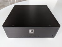
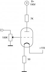
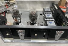
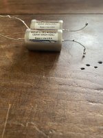
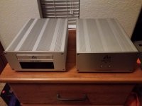
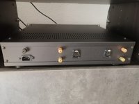
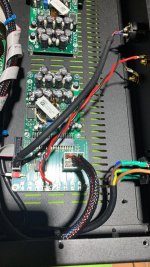
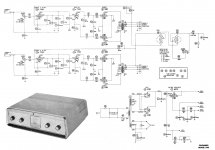
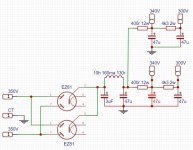
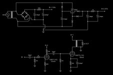
I put together a test setup consisting of a 12AT7 gain stage coupled to a 6AS7G dual power triode for the output stage, given that it has such low output impedance. I take it that the 6AS7G has much lower "technical" Z than 2500 ohms, but I got far and away the best results with what I have here. The transformer that I compared this one to is an Edcor GSXE10-2.5k - 16ohm since that's the closest match that I have on hand. I intend to try this with smaller iron in the future for a headphone amplifier.

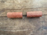
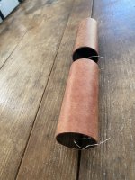
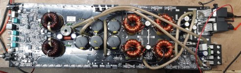
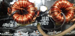
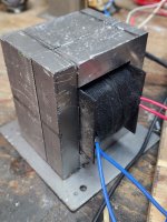
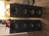
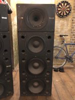
The microwave iron is freakishly huge for that purpose, but it's still in the experimental stage and it was easier to wind, given it's large size. The microwave iron that I have is already in an E-I configuration, and the "E" and "I" were bead welded together. I cut the welds with a grinder and pryed the "I" off, exposing the factory windings. I removed all three of those, along with the shunts. On one piece of iron, I ground the middle leg of the "E" down by a couple of mm to increase the air gap, but didn't notice any improvement over leaving it alone. I 3d-printed a bobbin for the new iron out of Nylon, and put it on a hand-cranked jig to wind it.

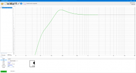
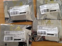
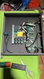
On my first attempt, I wound the primary and the secondary both in one large go each, laying the secondary entirely on top of the primary. I used 28awg magnet wire for both, since I have a large amount of it that's been salvaged from shaded pole electric motors, and isolated the windings from each other using Kapton tape. The results of that one were mixed. I wasn't overly careful with getting the turns very neat and even, and the result was a square wave output that had a considerable amount of rolloff. That is, the "corners" of the waveform were rounded on all frequencies. Not sure of "rolloff" is the correct term for that, but there it is.

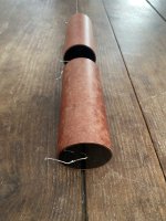
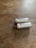
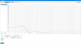
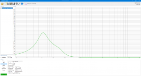
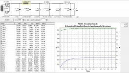
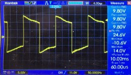
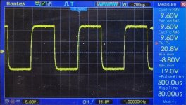
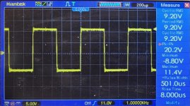
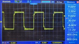
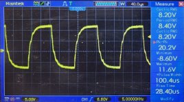
On the second attempt, I carefully wound four layers of the primary, then one layer of the secondary, then another four of the primary, etc until finished. I then spliced the segments together. I again isolated the primary and secondary at all transitions with Kapton tape. I fed a square wave into the amp at several frequencies and documented the output on a scope. I don't yet know how to calculate THD, so I apologize for not including that data. I observed near-identical performance at low frequencies. The edges of the waveform were somewhat rounded off on the DIY transformer at high frequencies though. Not so much that I found it unpleasant to the ear. I really like it in fact, and am excited that it worked anywhere near as well as it did. The trebel is nice and clear, but it's not as sharp and piercing here as I've seen with some other setups.

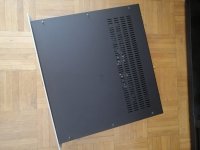
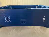
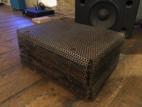
So anyway, there it is. The iron on the DIY trafo is a little janky looking, but one would be surprised what a little sandpaper and spray paint can do to remedy that. There's certainly room for improvement overall, but it's workable and I think that's pretty awesome.

Attachments

  • a 50Hz DIY OPY.jpg
    a 50Hz DIY OPY.jpg
    346.8 KB · Views: 354
  • a 50Hz Edcor OPT.jpg
    a 50Hz Edcor OPT.jpg
    338.4 KB · Views: 212
  • b 1KHz DIY OPT.jpg
    b 1KHz DIY OPT.jpg
    425.4 KB · Views: 220
  • b 1KHz Edcor OPT.jpg
    b 1KHz Edcor OPT.jpg
    515.9 KB · Views: 194
  • c 5KHz Edcor OPT.jpg
    c 5KHz Edcor OPT.jpg
    395.4 KB · Views: 211
  • c 5KHz DIY OPT.jpg
    c 5KHz DIY OPT.jpg
    450.9 KB · Views: 328
  • d DIY Transformer 2 crop.jpg
    d DIY Transformer 2 crop.jpg
    684.6 KB · Views: 461
  • d DIY Transformer crop.jpg
    d DIY Transformer crop.jpg
    445.2 KB · Views: 605
  • f Test Amp Schematic (more corrected).jpg
    f Test Amp Schematic (more corrected).jpg
    59 KB · Views: 413

Multiple Caps PSU question

Hi All,
previously posted on the Stan Curtis 60W Class a Thread.
I'm pretty new to this, so would like to ask a few questions:
I'm going to make a pair of these and in relation to smoothing caps in a PSU, the example above uses 2x 15000uf 'Sprague 36D' caps rated at 50V. These are obsolete, although there are new versions available and similar caps also available from other manufacturers. So I have a couple of questions if I may:
Whats the effect on a transformer feeding two of these giants as opposed to say 8 x 4700uf in parallel? in regards to the rectifier, is the charging time for the smaller caps quicker?
As a reference PSU, my Electrocompaniet EC25's have 4 x 4700 uf for one side feeding one set of rails (I think) and two 2200uf on the other.
I hear references to ripple current and ESR, the larger value caps do have higher ratings for both Ripple and lower ESR - certainly in the examples I'm looking at. Ripple is quoted at 100Hz. But what is the effect when smaller caps are in parallel? Do they smaller caps values add, multiply or neither? So if the ratings do add or multiply - this is better?
I have plenty of space in the chassis I'm using so either is viable, but I'd be interested in your thoughts.
Kind Regards
Joe

1 order crossover help

Hi guys ,
I'm an imbecile with electronics and hard-wired crossover elements ,this is why I would like to ask for help.
My woofer set up contains two DaytoAudio rs225 wired in parallel to get 4 Ohm`s . For one of the woofers, I would like to apply 1 order crossover limiting woofer to 200 Hz. I'm using active 4way crossover and would like simplify to 3 -way.

1666122709638.png


1666122867686.png

I guess, the main question is what type of coil should be used for the best result ?
  • Air core coils
  • Ferrite core coils
  • Copper foil coils
  • Iron core coils
  • Litz wire wax coils
  • Toroidal coils
Each driver is 8 Ohm's ,when wired parallel combined are 4 Ohm`s , what L1 (1 order filter) should be used ,for 8 Ohms driver or for 4 Ohm driver.

Thank you in advance for participating 🙂

Buzzing bass because of rubber

Hey there,

I am new here but would like some advice on fixing the subwoofer of my speaker. I got a pair of B&W DM320N and with one of them the bass buzzes.
I found out that if I pull it up every so slightly it gets fixed but when I remove my finger it starts buzzing again. I have no knowledge of speaker repair, so I am asking for some advice.
Login to view embedded media

A way to help core saturation in SE

Hi,
I was looking at this schematic of Pierre Johannet published on "L'Audiophile" and called "Super Némésis Compensé", seen on this French site:
https://www.bonavolta.ch/hobby/fr/audio/2sk135se.htm#2SK135 Single-Ended 3

1663483130194.png


"To improve the bass response and use a transformer without an air gap (larger primary inductance), it uses a second primary winding to avoid saturation of the magnetic core. This primary is powered (without any signal) by a second 2SK135, the current passing in an opposite direction cancels the magnetic field of the first primary."

I was thinking about a compromise to avoid any extra power consumption: use a custom dedicated winding on the OPT to supply the driver of the SE power tube, then helping to avoid core saturation (air gap still needed).

Searching for possible previous examples of this idea, I've then found Philips EL3541 amp with a similar approach (look point 70):
philips_el3541_recorder_sch.pdf_1[1].png


I was planning to ask Toroidy a specific SE OPT, and I would like to ask what specifications are needed to be communicated to get this advantage on core saturation.

Thank you all,
Roberto

Tannoy S900 Superdual value (CPA 12.3 /CPA 10 stack)

Hi, I have a pair of working Tannoy Superdual Series s900 stacks and if anyone is able to help me understand their value it'd be appreciated - I am planning to sell.

There is no documentation attached but I believe there is a CPA 10 mounted to the top of each CPA 12.3B stack.

As far as I can tell, they are both fully working, although in very used aesthetic condition, pictures attached. There is a little cosmetic damage to the CPA 10 woofers but they otherwise work great.

Each CPA 12.B stack consists of 2x 12" Long throw bass units, type 3112 - and 1x 12" Superdual Constant directivity dual concentric type 3138

Whilst they are not currently on, I have the speaker grills

There are more details here: http://www.lmcaudio.co.uk/assets/pdf/S900.pdf
and here (see CPA 12.3B): tannoy

Your help would be appreciated, and if you're interested in purchasing please get in touch,

Thank you!

Attachments

  • S900.pdf
    S900.pdf
    192.8 KB · Views: 163
  • IMG_0413.jpg
    IMG_0413.jpg
    887.2 KB · Views: 386
  • IMG_0414.JPG
    IMG_0414.JPG
    204.7 KB · Views: 340
  • IMG_0415.JPG
    IMG_0415.JPG
    242.2 KB · Views: 487
  • IMG_0419.JPG
    IMG_0419.JPG
    214.8 KB · Views: 450
  • IMG_0430.JPG
    IMG_0430.JPG
    475.6 KB · Views: 360

FS Kester 24-6337-9703 .4mm (.015 in)450gr

Kester solder (all info in title) Perfect to solder PC board and as good as many after market solder only if .Board must be clean like a new penny(I know these are out since long time now 😉) and wire (from capa, resistor,transistor etc). must be clean and with .4mm there is no extra solder on board and now and only this solder sound exc..Price as follow : :1 roll $30. + shipping, 3 roll $80. free shipping (this free shipping offer is good only for Tuesday Oct.25th ) it is promotional offer from Canada post and I give up to you . Price are in US$ and sale free shipping good only for US conus/Canada . Outside north america or need more than 3 roll send me PM
IMG_7585.JPG
IMG_7676.JPG
send me PM
IMG_7500.JPG
Projects by fanatics, for fanatics
Get answers and advice for everyone wanting to learn the art of audio.
Join the Community
507,744
Members
7,886,462
Messages

Filter

Forum Statistics

Threads
406,154
Messages
7,886,462
Members
507,744
Latest member
HMac60