CD player clock wire in Monarchy DIP

Interested in wiring a Monarchy DIP to a Magnavox CDP-460 CD player. The thought is to use the digital out of the CD player to the Monarchy. From the Monarchy back into the onboard DAC of the CD player. Has anyone ever done this? Is it a possibility?

The thought is to add a reclocker/dejittery thing in line without spending big bucks. Essentially like adding a tentlabs like item just outboard. I have a schematic for a Philips CD-160 which appears to be the same exact unit. Any thoughts would be welcome on how to accomplish this goal? Thanks in advance.

Hammond SEA Idle Currents

The Hammond catalogue here http://www.hammondmfg.com/pdf/5c0050.pdf gives a figure for "Maximum DC Bias". Does anyone know what this means?

Looking at the suggested tube applications, it would make some sense if this was a near-to-saturation peak current and the transformer was gapped for an optimum idle current of around half this value. When it comes to the 1638SEA, though, 45mA would not be optimum for an 845 or a 211 with a 10k load.

(I have tried asking Hammond about this, but technical questions are diverted to local sales staff who have no technical knowledge about the products they sell, and who are unable to find anyone in the Company who does.)

Amplifier with double output stage by Bob Cordell

Hello.
On page 68 of the book "A u d i o P o w e r A m p l i f i e r B a s i c s" by Bob Cordell there is a diagram
"Figure 3.13 Amplifier with double output stage". I tried to model it in lt-spice. That's how I described it (picked it up) and that's what I got. I got an order of magnitude more distortion. Did I do something wrong?
That was the first question. The second one will be next. So I made such improvements and got such a result. What do you think, colleagues, will this work in hardware in reality? I even made a psb for research in a hurry. Is there something that I didn't take into account, which is why my version of the amplifier may not work (I'm talking about both options, but of course I'm more interested in the second option).

Attachments

  • Cord_1_book.png
    Cord_1_book.png
    12.5 KB · Views: 891
  • Cord_1_my.png
    Cord_1_my.png
    20.6 KB · Views: 750
  • Cord_1_my_mod.png
    Cord_1_my_mod.png
    25.9 KB · Views: 776
  • Cord_1_my_mod_PCB.png
    Cord_1_my_mod_PCB.png
    94.2 KB · Views: 694
  • Cord_1_PH.png
    Cord_1_PH.png
    27.1 KB · Views: 567
  • Cord_mod_PH.png
    Cord_mod_PH.png
    26.7 KB · Views: 830
  • ааааа.png
    ааааа.png
    15.6 KB · Views: 911
  • Like
Reactions: pbilous

Set of 9 excellent UTC transformers, A-15, A-18, A-22, NE

Price lowered/Set of 9 excellent UTC transformers, A-15, A-18, A-22, NE

269,-eur

Price lowered

Up for sale set of 9 excellent UTC transformers :

SOLD 1. A-15 - 10/2.5K CT> 2K/0.5K - 2pcs, same series DP25
SOLD 2. A-18 - 15K CT > 80K CT

Sold! A-22 - 0.5K CT > 0.5K/0.125K - 2pcs, same series 7312
Sold! A-22 - 0.5K CT > 0.5K/0.125K - 2pcs
Sold! Northern Electric R20536A, Ind 0.323H/ 5:1

Nice condition.

Questions, info, pics on request, any time.

Transformers will be packed carefully with international tracking across all distance.
Sending from Ukraine. Payment by direct wire transfer.

FREE shipping to EU/UK.

----
See also other our items, we can mix all them together with our another items :

Grayhill 2, 3, 4 decks, single shaft rotary switches, up to 2x6, 1x12 poles

Grayhill 2 & 3 decks, dual shaft rotary switches, up to 12 poles

Canare L4-E6S pro audio cable 6mm, 4 wires 9 colors ~97m

Mogami W2944 pro audio cable, 2.5mm, 8 colors, ~236m

FS: Few different itmes - NEC relays, Meters, Caps, Cam, Cable

Attachments

  • DSC02883.jpg
    DSC02883.jpg
    499.8 KB · Views: 1,249
  • DSC02887.jpg
    DSC02887.jpg
    399.4 KB · Views: 1,149
  • DSC02898.jpg
    DSC02898.jpg
    469.2 KB · Views: 1,128
  • DSC02899.jpg
    DSC02899.jpg
    373.3 KB · Views: 1,142
  • DSC02900.jpg
    DSC02900.jpg
    349.8 KB · Views: 1,158
  • DSC02901.jpg
    DSC02901.jpg
    383.3 KB · Views: 414
  • DSC02902.jpg
    DSC02902.jpg
    291.3 KB · Views: 438

Classic Aleph Amplifier for Modern UMS Chassis - Group Buy

This is a group buy for circuit boards and MOSFETs to make a DIY Classic Aleph clone amplifier. This board set is designed to work with the diyAudio store UMS mounting pattern. The boards are flexible for making different Aleph variants, and power supply boards are also available.

You can see the main thread here: Classic Aleph Amplifier for Modern UMS Chassis

Group Buy #2 is now CLOSED.
Group Buy #2 closed 13 March 2022.
GB#2 Sign up sheet is here:
https://docs.google.com/spreadsheets/d/1w05jKUUwXxJUVIjuJXX3zeGQBRJD7ez2fiJqjWsOkS4/edit?usp=sharingLike Round #1 I'll reach out at the end to confirm order details, ask for email / name / shipping particulars.

GB#2 update 28 Feb 2022: I have purchased a bag of ZTX450's. There is a column to add those to your order in the GB#2 sheet to make life a little easier for folks. Stock is limited to 80 total. 2 needed per channel, 4 for a stereo pair. I'm not selling in bulk.

GB#2 Update 05 Mar 2022: I have matched a batch of FQP3P20. These are an alternative to IRF9610 for Q1-3. I'm adding these an option the sheet.

Post GB#2 Update - May 2022:
I have extra PCBs and MOSFETs available, please send a private message to me if interested. ZTX450's are gone.

Builder's thread is here:
https://www.diyaudio.com/community/...or-modern-ums-chassis-builders-thread.382316/

Attachments

  • Aleph 30+ Schematic Prototype V0.0d.jpg
    Aleph 30+ Schematic Prototype V0.0d.jpg
    962.2 KB · Views: 1,272
  • Aleph 30+ No Copper V0.0d.jpg
    Aleph 30+ No Copper V0.0d.jpg
    598.6 KB · Views: 1,033
  • Aleph 30+ Layout With Copper V0.0d.jpg
    Aleph 30+ Layout With Copper V0.0d.jpg
    693.4 KB · Views: 857
  • Aleph 30+ Layout No Copper V0.0d.JPG
    Aleph 30+ Layout No Copper V0.0d.JPG
    126.5 KB · Views: 918
  • Aleph Amp PCB-00a.JPG
    Aleph Amp PCB-00a.JPG
    146.9 KB · Views: 1,106
  • Classic Aleph for UMS-00a.pdf
    Classic Aleph for UMS-00a.pdf
    921.9 KB · Views: 551

LAMBDA Power Supply LPT-7202-FM

Greetings all.
I have a nice Lambda LPT-7202-FM power supply with some trouble. I have the service manual with the Part List, but all of the parts has a Lambda internal number. So I cannot replace the solid state parts like the integrate circuit that the number is FBT-031... I am looking for some chart able to give me the commercial part number.
Does anybody has this information that want share with me ?
Any help will be appreciate.
Best regards
Victor

Quad 405 parts refresh

Hello everyone,

I just got a Quad 405 that I want to refresh parts.

It is with the board ISS9 so I was wondering what are you guys replacing obsolete parts with ?

This is what I got so far.

1) All electrolytic capacitors were replaced by Nichicon 105C electrolytic.

2) Both 10000µF were replaced by Nichicon LKG1K103MKZ 80V instead of 63V to fit original size mounting ring (50WX80H) with soldering lugs like the originals.

3) Output transistors have already been replaced on one side, they are toshiba on both side but different year, I'd like to replace them with all the same version and year.

Original output transistor are 2SD424 and can be directly replaced by MJ15001 if I am not mistaken. If you have other suggestions, I'd be happy to see what you guys did.

4) Op map are missed match and one have been replaced (on the side where the output transistors have been replaced).

On the side that has already been repaired, the op amp is UA301ATC from 1977.

On the side that looks original, op amp is LM301AN from 1975.

I'd like to have both of these replaced but I have a hard time finding the right component. If you guys could tell me what you use on your 405s that are using the stock boards, I'd appreicated it !

Here are all the cross-reference I've found so far but not sure which one to pick at this point.

LM318, OP07, OPA134 and OPA277 all seem to match pinout but I am not sure about the rest of the specs.

5) The 40872 pre drive are originals from 1978. I think they can be direct replaced by TIP42C if I am not mistaken.

6) R30 and specially R31 have got a lot of heat, the circuit board has change color, I have redone soldering but the leads of R31 look oxidated. The value reading is spot on at 570ohms, they are 5% tolerance as the orignal schematic state for 10%. Not sure it is worth replacing them because of the heat stress they got...

Other than that, it's pretty much it. If you guys have any thoughts, I'd like to hear about it ! I tried to find information on the threads in here about the 405 but it seems many of you guys are having newer revisions and parts were not matching what I had here.

Again, I just want to refresh the components and that they be identical on both side and put the cover back on.

Thanks for all the input !

Attachments

  • 20210330_162633.jpg
    20210330_162633.jpg
    957 KB · Views: 672

RCA 5879 Phono Preamp

Does anyone have any experience with the 5879 phono preamp in the "RCA High-Fidelity Amplifier Circuits" booklet? The schematic is as follows.

5879 phono preamp.jpg


I have looked pretty extensively and only found a mention or 2 on the web, but nothing significant. I'm looking to build one as I have a bunch of the 5879 tubes and have used them in guitar and audio amps with good success. I have an entry level (at best) turntable with the Audio Technical AT-3600L cartridge, and I'm totally happy with the sound. That either makes me a noob or a philistine, or maybe both. Anyway, I proposed some changes as follows.

Phono-Preamp.jpg


1) Grid stoppers on all sections
2) 5879 screen bypass capacitor to cathode instead of ground
3) Instead of a 7025/12AX7, a 6AV6 and a 6C4 cathode follower (it'll be driving a 100k load). If the gain is too high, a 6AT6 can be swapped in.
4) Larger cathode bypass capacitors, because it's much cheaper in 2022

Also, how much of a difference would there be if I used a 22nF and 4.7nf caps for C5 and C6?

Any comments or insights will be greatly appreciated.

Ultra Slim Dual Down Firing Passive Subwoofers

Hi! Trying to build a bedroom system with dual (2pcs) sealed, passive, down-firing subwoofers. Main Speakers would be KEF LS50 so would need dual subwoofers to complement them and would need suggestions on drivers and any tips on the build.

GOALS: I don't listen loud in that room so 75 to 85 db max volume is okay, I just need the lower octaves fleshed out. As far as f3 is concerned I can be very happy to get stereo audible 40hz.

Crossover: Planning to crossover the Kefs at around 80hz since it's down firing so localisation shouldn't be that much of an issue. Ill be using a minidsp for this one.

Here's the challenge:
I can only build out these dimensions per sub woofer : Height 4" (4.5" with rubber feet) x Length: 20" x Depth 15"

Do guys have any recommendations on:
1. Low Profile Subwoofer for this use with a mounting depth of around 3+" ? Ideal budget would be 175$ for both drivers but the upper limit is 400$ for both drivers.

2. A cheap AVR that can drive the kefs and the subwoofer to around 85db.

This is a sealed subwoofer or so I'd like to imagine, any other suggestions on the cabinet build would be welcome.

Thanks in advance!

For Sale QA401 Audio Analyzer for Sale

Hello,

I am attempting to sell a QA401 Audio Analyzer by Quantasylum in nice and ultra-mint condition!
Since arrival, due to busy schedule, the QA401 here is used just for several times.
The QA401 I am selling is super new that I bout it directly from Matt in QA, every function is normal.

We are now in a severe semiconductor Crisis, and it seems it not going to relieve in a short time.
Many parts have incredibly long lead-time or prices.
So, I will just sell this out to invest other lab Test and Measure tools.

Send me a PM and We can discuss the price and shipment cost.

Regards,
Jen

Attachments

  • 20221024_012308257_iOS-1.jpg
    20221024_012308257_iOS-1.jpg
    383.9 KB · Views: 193

Amplifier for subwoofer

Hi folks, I figured I would pick your brains to see if someone has some ideas.
I've been thinking about adding a subwoofer to help the main speakers and add a little more bass (music mainly), but I'm unsure what route would be best.
My current amplifier has 2 (balanced) outputs from the DSP, but they are on two different DSP boards and can therefor not be summed there, so I need to sum Left and Right before the amplifier (if I would add two subwoofers later to eliminate room modes I would still want them to play the same).
I don't believe I need much power by the different subwoofers I've simulated, 200W seem to do it, if it's more then of course it's not a problem.
I might end up with a driver that has 4Ohm load, and accounting for a slight dipp bellow that is probably wise, so 3Ohm stable (?), but I guess I could find a driver that's more forgiving.
Is there any good options/solutions out there for DIY? Something that will make it as 'user friendly' as a plate amp that has two low level inputs.

Thank you in advance.
  • Like
Reactions: Ixnay

EV zlp 15" and elx 118p setup

Hello any advice would be greatly appriciated, i hVe just bought 2 elx118p subs and 2 ZLX15P tops. Can anyone tell me about the mic/line faderon the speaker do we put that quite high and the alter the master on the speaker? With regards to the subs do we setthem to around 120hz and on Boost for live show. We also use the allen and hearh wz3 16.2 s desk, so subs chained to mono and tops to left&right or from desk to top then link down ro sub each side. Any advice would be great thank you

Sony mic AC-2 for REW anybody tried it ?

Ok I searched this question has not been asked.
Im keen to get my REW system fired up and am on the look out for the bare min / cheapest calibrated mic.
I've given up on trying to build my own setup.
The two options Im looking are the Sony ECM-AC2 for 29$ on amazon.
The other option is the Dayton Audio iMM-6 for about 24$
I got all the parts to build my own. Like a 2 pin mic and some opamps. But calibrating sounds daunting.
But then on another post I was told to get a mic with phantom power, then to avoid USB.
My application is very simple freq res tests to see if the graphs supplied with drivers is accurate or not. And to get the data when they are not provided.

MarkAudio CHP-90 mica + SDDBH-T13.5R-AD (Dual Back-loaded Horn adding adjustable Duct, no sound absorber)

This enclosure has a unique construction and does not use sound absorbing materials.
Compared to enclosures of other structures, it produces a unique sound.

Login to view embedded media

Attachments

  • CHP90+SDDBH.jpg
    CHP90+SDDBH.jpg
    220.1 KB · Views: 526
  • 2020-06-06-01.jpg
    2020-06-06-01.jpg
    155.5 KB · Views: 360
  • 2020-06-06-02.jpg
    2020-06-06-02.jpg
    132 KB · Views: 472
  • SDDBH-T13.5R-AD-01.jpg
    SDDBH-T13.5R-AD-01.jpg
    184.2 KB · Views: 483

Help me figure out this 300B or ? output transformer please...

A friend of mine gave me a pair of very nice output transformers he has had for years, and I am trying to figure out the windings and impedance ratio and such, he says they were for an SE 300B or similar, and I could use some guidance to figure out the output windings.

I spent a few hours today driving the xfmr with a sig gen and measuring the output on my scope. It's not a normal secondary winding with the usual 4, 8, 16 ohm taps, it's 3 separate identical windings. I connected my sig gen to the primary winding, put in 40 VAC @ 1KHz and measured the following.

Each of the 3 output windings gave the same result, .75VAC out each. I tried connecting them all in series and made an LT Spice diagram so it's easier to see what's going on. The 300B SE could be anywhere from 2K to 5K plate load depending on plate volts and anode current. The measurements seem plausible but I could use some help to determine what I really have here. My ultimate goal is to scratch build an SE 300B with minimal driver stage, maybe xfmr coupled, not sure at this point, I'm working my way in from the back end. 😱 My speakers are Big Reds, 16 ohm. The turns ratios I came up with gave me what seem to be correct results for the 16 and 8 ohm windings, the 4 ohm seems way off. I won't say any more as I don't want to influence your thoughts....

Attached is the diagram I made of the transformer and AC measurements @ 1KHz. Ignore the Lx desinations, I couldn't figure out how to delete them in LTSpice.

Any help, much appreciated.

Cheers

Attachments

JL Audio 500/1 rev 10

This amp came in with IRFZ44 PS fets and 47ohm gate resistors blown in the PS.

On the output side; Q506/Q507 IRF540 completely shorted and the 100ohm resistor very close to the MIC 4427 crispy but still reading well.

I replaced that 100ohm resistor, all 4x IRF540 with IRF540N, and put a single IRF3205 into each PS bank.

Amp powers and plays out of the sync briefly under 4-ohm load to about 10 amps draw.
Seems like it might be OK but I dont really know these amps well enough to verify full operation just yet.

On the 540 vs 540N, seems parts for 540 and 540A may be scarce which is why I installed 540N for right now. The only 540 I am reluctant to try are the expensive Vishay brand.

Any pointers on what else I might need to check next? If the IRF540N are not suitable are there any suggestions? I read the entire JL 500/1 page but there seems to be a LOT going on with these which I am now trying to get familiar with. I usually pass on servicing JL but alas here one is.

Thank you

Single Board Computer Manufactuer Ranking

Since the Raspberry Pi folks are still having production issues I'm entertaining ordering a competing product to tinker with. Has anyone done a shootout or at least compared the boards first hand. This will be used as a streamer and whatever I get will likely be overkill from a power standpoint, and that's fine. My pi4 is several years old and will one day be repurposed for something else, so I don't mind having more horsepower than I need for a given application. Things I'm curious about...

Does one company have an edge on board power management (less noise)?
Does one company have an edge on USB implementation?
Does one company have an edge by using a better clock or a better implementation?
Not necessarily looking to get into a discussion on why these things do or don't matter. The questions are what they are. Some of the manufacturers I'm looking at include:

Pine64
Odroid
Khadas

If you have any specific experience with something you liked, I'd love to hear about it. My current plan is probably DietPi or LibreElec. Also open to personal experiences there. The end goal is to install Roon bridge. Thanks in advance.

DAC ES9038 PRO GR 2

After the great success the first version Quanghao opens a new group buy to produce a new series of DAC ES9038PRO:
[URL="http://quanghao.com/product-es9038-pd94325.html"]10th birthday anniversary[/URL]

Es9038 PRO DAC - Design by Andrea Ciuffoli-Quang Hao

  • Based on the ESS Sabre32 Reference (ES9038PRO) DAC chip
  • Support 44,88,96,192,352,384KHz PCM and DSD to play SACD ISO.
  • Full ground isolation from USB module
  • On board reference 100MHz Crystek oscillator with a jitter of 0.5psecUltra fast oscillator buffer

Output: Stereo balanced output impedance: 202 / 4 = 50 ohm
DC-ouput: +1.65VDC.
Output impedance: 100 Ohm.
Output: 2-Channel (stereo) outputs can be used in current-output or voltage-output mode
(depends on output stage used)

Input: 4 inputs:
1. USB -match with Amanero USB (not included). Have pin I2C for other USB
2. Spdif
3. AES/EBU.
4. Optical

Digiltal supply:

1.2V core: LT3042
3.3V oscillator: LT3042
3.3V digital: LT3042
3.3V Top-botton chip
3.3V USB: LT3042 (If you not like us 3.3v from Computer for USB)

Analog supply:

1.2V analog (left and right separated): LT3042
3.3V analog (left and right separated): LT3042
5V for LCD: LT1117
5V Analog supply: LT1117
5V Digiltal supply Digiltal supply: LT1117

Controls and features:
1. Standby mode.
2. High volume display.
3. 20 x 4 LCD display.
4. Select the 4-way input and display the frequency on the LCD screen
5. Fuse protection - 220 VAC power supply / 5W
6.Turn on, off with remote control or buttons.
7. Simple and appropriate use for DAC chips: ES9038PRO, ES9028PRO.
8. Set up customizable protocols such as: volume, input as you like.
9. Select modes such as filter, frequency, left channel right.
10. Special and unique - Store settings according to your preferences:
A, Keep the big picture to the desired: lowest -100dB, largest 0dB.
B, Select and store left or right channel output - No need to reverse the output.
C, Selectable filter modes: (Pass band): 47kHz, 50kHz, 60kHz, 70kHz.
D, Option: PCM Filter Characteristics
E, Selectable filter modes: (Pass band): 47kHz, 50kHz, 60kHz, 70kHz.
F, Option: PCM Filter Characteristics: Fast, Slow Roll-Off, Apodizing, Hybrid, Brickwall.


On-board DAC ESD9038PRO includes:

1. ES9038PRO chip.
2. Clock 100MHz CCHD-575, Ultra-Low Phase Noise Crystal Oscillator.
3. All Input connecters, Amanero USB (not included)
4. All low noise Lt3042
5. LM1117

Use: it is simple and need:

1. Transformer 15VA to 25VA: 2 x 6 - 8VAC: Talema 70050 or Talema 70060 Or equivalent
2. Use LCD Control board off Andrea-quanghao for ES9038PRO, ES9028PRO

This options are available and here the new cost:

1) DAC module assembled and tested with all components:
- ES9038PRO chip,
- CCHD-575 Ultra-Low Phase Noise Crystal Oscillator: Ultra-low phase noise CMOS oscillator provides 168-dBc/Hz noise floor | Electronics EETimes
- 7 x LT3042 linear power supply regulator 1uV noise
- 5 x LT1117 linear power supply regulator.

- All input connectors
- BUT NO OUTPUT STAGE
price 400$

2) DAC controller- Encorder + 4 x 20 LCD:
see video for LCD: https://www.youtube.com/watch?v=4owu...ature=youtu.be

  • 20x4 LCD
  • Infrared remote command
  • Remote silver
  • All connectors
price: 150$

3) Amanero module
Please purchase from: : Amanero Technologies

4) Transformers, for the DAC: 6.5V x 2 / 15VA
price 30$ each

5) Chassie: include: weighs: 10 kg
- 1 x chassis, iron powder coated black, size: 420 x 380 x 86 mm,
- 1 x front surface silver anodized scratch: 430mm x 92mm x 10mm.
- 4 x rubber feet: 20mm high, 50mm wide
- 2 x aluminum knob 26mm x 38mm
- 1 x Plug + switch
- 20 x copper base 10 x 3 mm
- fasteners: catch the front, the back, motherboards, storage tank foam.
price 150$


Shipping by TNT:
A. The options : 1 to 3 : 60$ ( the same price)
B. The options : 1 to 4 : 75$ ( the same price)
C. The options : 5 : very heavy, calculated separately for each country.


This project is a great DAC, I want to share with you,
However, I need your help, let me do it!

The minimum required number 15 set: DAC+ Controle DAC

I started producing.
Payment: half the amount for the selection, the remaining amount of money + shipping payment before shipping.
Payment by paypal: quanghao168@yahoo.com.vn
Paypal free: 2%.
Note: Because this is a shared project, and need money to produce,
Therefore, you have paid half of the money for the project will not be allowed to get back the money - this is a mandatory provision of this buying group!


One-year warranty.
You send me back defective products and carrier billing yourself.
I return it to you and I pay for shipping to you, after you're done!

Attachments

  • Manual Kit  ES9038PRO DAC+ Controle2.jpg
    Manual Kit ES9038PRO DAC+ Controle2.jpg
    499.9 KB · Views: 5,539
  • Structural-design-ES9038pro.jpg
    Structural-design-ES9038pro.jpg
    405.5 KB · Views: 5,333
  • Structural-Supply-ES9038pro.jpg
    Structural-Supply-ES9038pro.jpg
    413.4 KB · Views: 5,173
  • Manual Kit  ES9038PRO DAC+ Controle7.jpg
    Manual Kit ES9038PRO DAC+ Controle7.jpg
    468.3 KB · Views: 5,145
  • Manual Kit  ES9038PRO DAC+ Controle5.jpg
    Manual Kit ES9038PRO DAC+ Controle5.jpg
    203.3 KB · Views: 5,092
  • Manual Kit  ES9038PRO DAC+ Controle6.jpg
    Manual Kit ES9038PRO DAC+ Controle6.jpg
    182.1 KB · Views: 1,081
  • Manual Kit  ES9038PRO DAC+ Controle8.jpg
    Manual Kit ES9038PRO DAC+ Controle8.jpg
    269 KB · Views: 990
  • Manual Kit  ES9038PRO DAC+ Controle9.jpg
    Manual Kit ES9038PRO DAC+ Controle9.jpg
    306 KB · Views: 944
  • Manual Kit  ES9038PRO DAC+ Controle10.jpg
    Manual Kit ES9038PRO DAC+ Controle10.jpg
    261.7 KB · Views: 891
  • Manual Kit  ES9038PRO DAC+ Controle11.jpg
    Manual Kit ES9038PRO DAC+ Controle11.jpg
    294.9 KB · Views: 982

Kenwood LM-07 Chassis?

Ages ago I bought on eBay a Kenwood LM-07 Mk11
It died an inglorious death but I have been hanging on to it.
I just started to disassemble it and found NEC capacitors A1007A & C2337A and not the high speed originals so it had been rebuilt at some point before I bought it.
I am assuming that all the T0-3 on sale from China are clones [ to put it politely] but I am wondering if there is anything I can do to reuse the chassis as it really is a work or art in some respects

Diypole makes a monopole

SB12NRX25-08 4" woofer and SEAS Prestige 27TFFNC/G 1" tweeter. You can see it was a little windy today reflected in the low frequency response. Volume for woofer is a tad under 2 liters. Tweeter is just setting between strips of open cell foam, but I have determined where it will sit in relation to the front edge now.

No wires will exit the rear in the final speaker, they will be active and wireless stereo. Building a base to house the amps and power supply is next. I turned all the pieces by hand on the lathe. The wood is Spalted Maple with all kinds of worm holes and bug tracks, I could stare at it for hours lol. It has all been molded with extremely hard epoxy before turning, and is generally 3/4 to and inch thick. I wanted the effect of blowing through the wood and seeing into the speaker in some spots, very happy with the result. More layers of epoxy will be dumped over it before it's finished, definitely not going to leak anywhere lol
Crossover is 18db/oct Butterworth at 1800hz on the tweeter and 24db/oct LR at 1600hz on the woofer. The resulting acoustic crossover point is 24db/oct at 1500hz. These measurements are at 50 inches. Only the measurements at 150 and 180 degrees have a significant dip, and up to 60 degrees off axis it is practically omnidirectional up to 5000hz. The VituixCAD data is for 0-180 degrees.

I'm sitting between them in the nearfield on my shop bench as I write this and thoroughly enjoying it.

Attachments

  • IMG_20220820_180445329_HDR~2.jpg
    IMG_20220820_180445329_HDR~2.jpg
    531.8 KB · Views: 241
  • IMG_20220908_122845881_HDR~2.jpg
    IMG_20220908_122845881_HDR~2.jpg
    486 KB · Views: 260
  • IMG_20220908_122938944_HDR~2.jpg
    IMG_20220908_122938944_HDR~2.jpg
    436.2 KB · Views: 250
  • IMG_20220910_141653469_HDR~2.jpg
    IMG_20220910_141653469_HDR~2.jpg
    1.2 MB · Views: 241
  • IMG_20220910_141717805_HDR~2.jpg
    IMG_20220910_141717805_HDR~2.jpg
    323.4 KB · Views: 258
  • sbntff 6 pack.jpg
    sbntff 6 pack.jpg
    208.4 KB · Views: 236
  • sbntff outside 0-60.jpg
    sbntff outside 0-60.jpg
    64.1 KB · Views: 220
  • sbntff outside polars.jpg
    sbntff outside polars.jpg
    70.2 KB · Views: 202
  • sbntff outside tweeter inverted.jpg
    sbntff outside tweeter inverted.jpg
    68.4 KB · Views: 242

Alpair 10.2 in a small cab - BSC?

I put a pair of Alpair 10.2 in a repurposed pair of cabs from an old pair of B&W DM100 speakers.
They do make pretty decent bass, but the mids ended up 'shouty' sounding. There was too much midrange; they sounded far too 'forward' and 'aggressive'. Not horrible, but noticeably off.

I have a collection of 30-some odd years' worth of speaker chokes of various values, and a decent selection of 5W wirewound resistors. I read up on baffle step compensation networks, calculated a ballpark set of values, and wired them in.

After experimenting for a few days, I wound up with a 3.3mH choke and 10R resistor in parallel, placed in series with the + lead from the amplifier to speaker + binding post.
The - lead from the amplifier is connecting directly to the speaker's - binding post.

I used two pairs of speakers I have as references, and tried to get the Alpairs to sound as close to those speakers as possible. (The other two speakers are JBL Studio 530 and Snell E/III.) I got close enough to where I'm now happy using the Alpair 10,2 speakers as my nearfield PC speakers.

My question is, do my BSC values sound in the ballpark, or am I making a mess of things?

Pioneer GM-201 1986 amp

Hello Guys hope you are doing well.

I got a pioneer gm-201 and I'm trying to make a cable to connect it from the din 8 pin connector to a newer eclipse cd8443 head unit. I've seen the schematic on the manual and signal are pin 2-5 and 3 is ground they go to the RCA from the head unit
7 is illumination goes to +12?
4 is mute. Maybe to mute cable from head unit or unconnected?
But I'm confused with the swd and unswd cables pins 1-6 . Where should they go?

Please any help would be appreciated

FS Firstwatt F3 boards completed

I have for sale a Firstwatt F3 board, completed and in perfect working condition. Worked for some 30 hours in total. I will include a pair of the llu and the power IRFS as spares.

The price is 100EUR + shipping and paypal fee. The boards are located in the EU.

Attachments

  • IMG_20210204_225115.jpg
    IMG_20210204_225115.jpg
    479.6 KB · Views: 279
  • IMG_20210204_225117.jpg
    IMG_20210204_225117.jpg
    504.8 KB · Views: 282
  • left.jpg
    left.jpg
    50.3 KB · Views: 267
  • right.jpg
    right.jpg
    43.3 KB · Views: 272

UK subwoofer building - Where's the value at?

First I must note that I'm new... So please excuse some possibly obvious mistakes🙂

My problem is as follows: I'm in the UK and hoping to build a sub for my secondary system, I'm having trouble finding components at prices that don't end up as near as "might as well not risk it" to a sub I'm already running on my main system which I'm more than happy with.

Having bought a nice new system (speakers/amp/dac) for the bedroom, it needs a subwoofer. It's nothing high end, but in many ways betters my downstairs "main" system - So I don't want to do it a disservice by partnering it with junk. This is a music system. If it can handle music as I'd like it too, occasional movies will be no trouble. I'd love to build my own subwoofer if I can make it financially not-silly to do so... I enjoy building things, but parts seem rather expensive.

The crux of the matter is this: I've got a BK XXLS400 and some DSP in the front room doing a wonderful job, and I'm having trouble figuring out a driver/amp/box pairing that would out-do the equivalent B-grade BK. Now, I'd be happy with a XLS200 for this new system (£315). But when a XXLS400 is £410 and shakes my window frames when needed while being quick enough to blend in well enough for my ears, it's a tough sell. I've heard subs that do some incredible things, but this is a home system, my expectations are realistic.

As an exercise, finding a driver that models how my 400 performs on my main system, then looking at the price of plate amplifiers to power it, I'm left wondering how to get anywhere close.

My hopes are thus:
-I'd like bass down somewhere into the 20-somethings. Basically I'd like to be able to play The Mountain Will Fall by Dj Shadow without having to imagine the low notes.
-It doesn't have to be loud, but it has to be quick and deep (enough).
-I don't mind if I have to make the box a reasonably daft size/shape, but this isn't a dedicated hifi room.
-As mentioned, I can tame the room with DSP.
-I would quite like a plate amplifier on the back powering the thing. That's not a deal-breaker, but it'd sure be nice having all the right controls in what I consider the right place.

Is that possible for a novice builder, when I suspect the XLS200 at £315 (or worst case the 400 at £410) will do me well enough?

I can't seem to model anything that gets close - but then I am a beginner at this driver/box modelling stuff.

Thanks for reading,
J James.

Optical encoder PCB + spare encoder for Muses 72323 Volume control

I made a PCB for Bourns EM14 optical encoders.
This board is compatible with the MUSES 72323 volume control made by Meldano on this forum.

One board is fully populated and is working perfectly, I have one spare optical encoder.
Encoder type is: EM14R0D-M20-L064S
I moved from the ALPS to these Bourns Encoders as I had bad luck with the ALPS going bad pretty fast, the feeling when rotating the Bourns is from a much better level as well.
Reason for sale is that I moved from 64 to 32 PPR. 64PPR was about 1 full rotation to get from 0 to full output in my system.


As you will notice on the pictures, a 78L05 is installed to take care of the 5V for the encoder. I'm supplying this board with 12VDC, offcourse 15V is no problem either.
The 3V3 is not needed for this board to function.
The circuit is based on: https://www.diyaudio.com/community/threads/muses-72320-electronic-volume.220792/page-27#post-6419562

Populated board + spare encoder = €50 excl shipping. (this is lower than the price of the 2 encoder together!)


Any body interested? I will only sell both items together.

Attachments

  • IMG_2748.jpg
    IMG_2748.jpg
    1,002.1 KB · Views: 334
  • IMG_2750.jpg
    IMG_2750.jpg
    490 KB · Views: 356
  • IMG_2749.jpg
    IMG_2749.jpg
    440.5 KB · Views: 378

PC upgrade. 250 watts ?

Had a bit of spare cash (rare these days) so looked into buying a better 12th gen processor.
I bought a 12400F but found it doesnt have graphics onboard.
So decided to go for 12000 series but with graphics and something a little faster.
The 12600k works at 4.9GHz and takes about 125 watts max.
I also looked at 12900k 5.2GHz but that takes up to 250 watts max !
So for 300MHz more it needs twice the power !
So went for the 12600k.
Seems to do the job well for what I need it for, mostly PCBCAD work and software development.
The 12900K is also about twice the price of a 12600k for not a big difference in performance.

Restored, A.N.T. Modified & Fine Tuned Sony TC-K850ES 3 Head Cassette Deck Quartz Locked Direct Drive

Hello

I Had this non-working Sony TC-K850ES cassette deck in my shop for some time. A customer who was interested in this model messaged me to buy this. I restored the deck with original genuine Sony Pinch Rollers, Belts and an assortment of gears for the mode encoder mechanics. Replaced the SMD capacitors on the direct drive board and replaced the Standard capacitors on the motor controller board with Nichicon Fine Gold. After restoration the deck records and plays back as intended. The head was in good condition despite it being permalloy material. The deck has Nichicon muse in the recording and playback chains. A solid built machine

I noticed the deck was using some outdated op amps and a low grade 4066 chipset which downgraded the sound quality potential. I went ahead and replaced all op amps in the circuit with Texas Instruments NE5532P and the 4066 upgraded to the ANT4066B. A significant improvement now in recording and playback. Much better than the original state

I added the original advertising stickers specific to this deck as a finishing touch

The deck is now complete and with the new owner.

5-F0-F65-B6-909-B-4966-BAB5-7-FAEED70-A445.jpg

6.jpg

0-F0884-E9-9-E43-4498-BB41-C727-AB2303-DB.jpg

IMG-7871.jpg

IMG-7878.jpg

Rendered-Image.jpg

7.jpg

1.jpg

2.jpg

3.jpg

4.jpg

5.jpg

3.jpg

Rendered-Image-1.jpg

Rendered-Image-2.jpg

2.jpg

6-D4216-BF-B72-A-4285-A78-E-F986-AC71144-B.jpg

9.jpg

Rendered-Image.jpg

IMG-8521.jpg

For Sale High bias modded Aleph J pcbs

Hello,

I have for sale my modded Aleph J pcbs. These were just pulled out from the enclosures and replaced with an output stage similar to the F4.
The pcbs were come from Peter Daniel.

The pcbs have the aleph ccs resistors and the mosfet degeneration resistors replaced with a lower value, 0.33r, which gives higher bias current, 1.6a/fet.
The ccs that biases the front end is replaced with an tl431+bjt ccs.

I used the pcbs as monoblocks with 30x16x4cm heatsinks, having 2 mosfets on one heatsink(4 heatsinks in total).
The heatsinks were sitting ~30c above room temperature.
The power supply voltage was close to 22.5v.

All caps onboard are elna bypassed with ero.

The mosfets and the teflon isolators were cleaned.

I am attaching a few thd measurements.
My speakers are a bit inefficient at only 87db and also low impedance, 3.4r. This was the reason of needing higher bias.

Price SOLD

Attachments

  • 4164839C-B78A-4767-ABCC-7E01F298DBE1.jpeg
    4164839C-B78A-4767-ABCC-7E01F298DBE1.jpeg
    441.2 KB · Views: 279
  • A7511B87-10DB-4AD2-82A6-EA0F721B7692.jpeg
    A7511B87-10DB-4AD2-82A6-EA0F721B7692.jpeg
    637.3 KB · Views: 277
  • 1v out aleph j.jpg
    1v out aleph j.jpg
    109.9 KB · Views: 257
  • aleph 3.4r 7.6vrms 22vpp.jpg
    aleph 3.4r 7.6vrms 22vpp.jpg
    102.7 KB · Views: 195
  • aleph 6.7v 3.4r.jpg
    aleph 6.7v 3.4r.jpg
    109.5 KB · Views: 262
  • Like
Reactions: Mikerodrig27

Magnepan 3.7i - Convert crossover to parallel

I have a pair of magi 3.7i and would like to convert the crossover from serial to parallel.
So I can bi-amp them and play around with better parts.

From the schematic it looks like, and I am guessing 😊

12 db on the tweeter
6 db band pass on the midrange
6 db on the woofer

Am I right?

MG37_schematic_full_3.png


Found the schematic here http://www.integracoustics.com/MUG/MUG/tweaks/neolith/
I don't know where I can find neolith so I hope it's okay to use his material

First Watt F3 Project

I have far too many projects either on the go or waiting to be picked up so I'm going to cull some.

A set of PCBs and matched LD1014D FETS, courtesy of Nelson Pass, for a clone of the First Watt F3 amplifier. Purched via a GB here on DIY Audio, details here;

https://www.diyaudio.com/community/threads/f3-clone-board-set-group-buy.373750/

I have:

2 x amplifier boards
2 x output boards
2 x PS boards
2 x LED boards
2 x XRK mpunting boards for LD1014D devices

The LD1014D devices were a gift from NP to the DIY audio community and I'm not looking to make money on them so the cost is just to recover my investment in the PCBs - looking for £25 plus shipping at cost.

vIQypVt.jpg

3-way quasi-coaxial cardioid speaker

Hi to everyone,

i wanted to share a project i was working on for a while. These speakers are a clone of the concept utilised by the german company "ME Geithain", which famously supplies the german state broadcast. The company is located in the former East Germany and the boss Joachim Kiesler was building speakers behind the iron curtain using technologies such as waveguides (RFT BR25/BR50) and line arrays (Geithain ITS50). The first quasi-coaxial speakers (Geithain RL900) also originated back in that time and were first supplied to East german Broadcast and opera houses. These were utilising classic bass-reflex enclosures with the addition of the cardiod version in the early 2000's.

The goal of this project was, to understand the influence of different damping materials as well as port size on the directivity of the woofer.
In the future, i want to compare the quasicoaxial arrangements to more traditional 3-way setups with a large dome and cd-horns.
But first, more about the current setup.

The tweeter is a Dayton ND25-TA which works fine for the job. Seas 27TFFNC/G would probably be better, but i was a cheapskate.
The midrange is a Faital 3fe22 without enclosure but damped with a basotect ring around the rear.
The woofer is a Transfer Audio AR 25. Again Seas L26ROY would be better but i got these for 30€ a piece and they have an xmax of 9,5mm one way.
The crossover is done using EqualizerAPO so there is only one D/A conversion.

Crossover is at 800hz and 3,5khz resulting in the characteristic dip in the directivity index between 3 and 5khz. This will also investigated further. ME Geithain has an in depth understanding of speaker directivity but decides purposfully to put this dip in the directivity index.
the enclosure meassures 33x36x25cm and the rear port equals 135cm² (1/2 Sd) At the moment the damping is archieved by stuffing the eclosure with rockwool but in the future i want to switch to dense polyester damping material. I will post meassurements of the enclosure with and without damping material next week. For the general size, there is a great excel file on Linkwitzlab which calculates the bass roll-off as well as the resonances which occur at the back of the speaker an need to be damped.

Attachments

  • 1662465788151.jpg
    1662465788151.jpg
    806.8 KB · Views: 421
  • 1662465788169.jpg
    1662465788169.jpg
    378.9 KB · Views: 484
  • messung 0° 45° 180°.png
    messung 0° 45° 180°.png
    32.7 KB · Views: 368

DAC: CS4398 with CS8416+CM102s

As title says I did buy this eBay DAC board and associated enclosure from along1986090. Used my transformers.
CS4398 with CS8416+CM102s, provides coaxial SPDIF and USB inputs.
First impressions:
Enclosure definitelly well done, with (almost) all necessary hardware, holes in exact locations to match the board. Kind of long (10", plus 1/4" front aluminium plate), I guess it can be used to add a dedicated headphones amp.
I did buy the pre-solderd board. Inspected with the magnifier glass showed an OK grade of soldering. PCB is in filled ground technique and parts are like shown in the picture.

Initial tests had a sligtly distorted signal and analized with my E-MU1820m showed a really bad signal. I did replace the 5532 that was on board with LM4562 that I hade around and everything started to look better. I suspect that the 5532 was either a fake or a damaged exemplar. There is no capacitor or resitors on OpAmp outputs, so it is easy to be damaged.
At -2dB looks decent. The output stage overloads my ADC input at higher than -2dB (all the other DAC's that I tested didn't manage to do that).
The output stage is not done per recomended schematics in the datasheet.

USB input:
CM102 locks only onto 16bit/48kHz signals. 16bit/44.1kHz is not supported in Windows7 mixer (WASAPI).
If looses the connection with the PC, static noise is outputted till the next power off/on cycle. The automatic switching could be done better I guess...
Altough in Win 7 there is no need for drivers, here is a package that provides a little more that basic USB. This driver looks like it does the resampling to 48kHz automatically.
278508d1335117300-dac-cs4398-cs8416-cm102s-lisa_-3db_usb.png


Coax SPDIF:
Locks on 44.1-96kHz, 16 or 24 bit. I don't have a SPDIF source capable of 192kHz to fully test the CS8416.
278507d1335117300-dac-cs4398-cs8416-cm102s-cs4398-2db.png


Using Foobar with resampling to 48kHz would allow USB connection to work at any rate, but I do prefer the coax.

All in all, sounds decent, especially for the price. THD+N with LM4562 is at -94dB. OpAmp upgrade is strongly recomended and looks like some of the AC grid noise could be reduced by better filtering.
Direct coupling of the outputs leaves some higher levels of 10Hz noise creep into the output chain as seen in the coax graph (at USB I forgot to extend the range below 20Hz).

The seller give the schematics (at my request).

Attachments

  • P1090836_small.jpg
    P1090836_small.jpg
    571.2 KB · Views: 3,725
  • P1090811.jpg
    P1090811.jpg
    511.1 KB · Views: 3,525
  • CS4398-2dB.PNG
    CS4398-2dB.PNG
    56.6 KB · Views: 5,458
  • lisa_-3dB_USB.PNG
    lisa_-3dB_USB.PNG
    53.8 KB · Views: 5,465

PA Audio PW600 died, can I use a 1000w class d pwr amp and a 60 hz signal generator?

I brought this around 25 years ago (sn#12)when I had a second home in the country as the power was horrible and all over the place (105 to 127) and noisy
It died around a year ago and sadly ps does not fix it and offers a discount on other stuff
Around 10 years ago after hurricane ida the damage up here was really bad and I fought the power company and got my own pole and transformer ,it's been fantastic
So instead of salvaging for parts or dumpster contenders,I thought a simple 60 hz signal generation to an amp to get 120 v out
Am I dreaming or is it possible as it's just a ac generator
Thanks

BMR Group Delay

Hello everyone, I was watching Erins Audio Corner a few days ago with Dr Geddes as a guest and he briefly mentioned group delay and used BMR drivers as an example, then said no more on the subject. I became very interested in the tectonic 2” BMR after reading Erins shining review. It seems like the ideal driver for my tastes as I can’t really hear sparkle (I’m 41 as of today) and the frequency and polar response are stand up, which is much more important to me.

But, I worry now about group delay distortion smearing in the time realm. I imagine that the sections resonating semi independently might take enough time in relation to the higher frequency cycles to matter where we’re very sensitive. Would anyone care to share their understanding of this?

Some might be tempted to point out that if I have to ask then I obviously don’t notice it even if it exists and it doesn’t matter then. The thing is years ago I didn’t know about the stereo illusion but now I do, and it matters. There was a time when I didn’t know that my car door speakers were beaming and there was a major problem in the upper midrange response at the listening position, and that most certainly mattered. I wonder if the tradeoff for the wide dispersion is group delay as Mother Nature gives with one hand while taking with the other. Is this concern valid?

I very recently began designing and assembling a small stereo system from the basic components. Kabd amplifier boards, open frame power supply, raw drivers, ect. I chose a two way system with the BMR 2” not because I couldn’t implement a decent three way, but because I felt I didn’t have to with the BMR. If there’s a real problem with the BMR’s I’ll be looking at the RS100 or RS75 and one of the reference tweeters. There’s a chance I’d go for one of the other Dayton 28mm tweeters because of availability. I have some beliefs regarding crossover points that might be too careful but this can wait to be discussed under after the group delay thing has been sorted.

My bookshelves currently have the Tectonic 2”, Anarchy 704, and RSS210 passive radiator on ~60w and 15w respectively. I’m really happy with the result but I want to make sure I’m not missing something that once I perceive it it’ll bug me ferociously. Btw is Erin @bikinpunk here? He’s Erinh on diyma where I’ve basically learned everything I know.
B30B1EDA-6F7B-45F6-B2B7-A143F0689BB3.jpeg


CBDEDEC5-F177-477A-9446-41FF48EC0E48.jpeg


7B5D0B2F-E556-4FB8-A94B-BCD69942B910.jpeg

Very low frequency vibrations in belt turntables.

I'm temporarily going back to my Thorens TD160 turntable, in order to capture all my LPs in high resolution, cleaning the records from surface noise, clicks and pops at the same time. I have already done that with a friend's Luxman high resolution system, with V15 cartridge, and the results were fantastic.

The I proceeded, using Audacity, to clean the LP from all surface noise and eliminated all the clicks and pops I could find. Capturing at higher resolution, like 96KHz, would allow higher accuracy in the noise elimination. In any case, the files sound excellent. We still have to make a comparison between the original LP and the CD with the processed files and see how they sound.

Now I'm the process of building the RIAA preamp. This has been commented elsewhere, which generated a very constructive discussion, where I learned a lot, using LTSpice simulations to compare results from several highly regarded commercial designs.

The choice for the first preamp will be one using two FET ICs with a passive RIAA network between them. My idea is to use an existing RIAA kit sold by AliExpress, which will provide the pcb and some of the parts, then buying the ICs and some specific passive parts to substitute key ones in the RIAA filter.

My question is what to do with the very low frequency vibration, probably around 3Hz, that seems to occur apparently on all belt turntables. That's what I have been told it happens. My friend's turntable, where I made my first capture, also had them. Of course they didn't show on the captured digital tracks.

In my past turntable arrangement, I used a discrete two stage passive preamp, and the vibration was there alright. This preamp used a 470n polystyrene input series capacitor as high pass. To visually cure the vibration I had to lower the capacitance to 100n, which didn't seem to affect the audio quality.

Now I ask: should I worry about that? Can that low frequency intermodulate with higher octaves response?

The circuit I'm using now does not use an input series capacitor.

Help with wiring series stepped attenuator

Hi guys,
I don't suppose someone could help me out with the wiring on the stepped attenuator I'm building?
I've attached a photo of the unit, and the resistor values i bought are for a series attenuator, whereas most of the guides online seem to be for the shunt type.
If I attach my meter between pin 1 and 3, the resistance adds up in series from zero resistance upwards as i decrease the volume from max, or if i connect 1 and 2, it increases as i increase from minimum volume. And this has lead to a couple of questions.

1. where should my ground, signal in and signal out be attached.
2. should RX or RY be the largest resistor? (i'm using the 50k figures from https://www.goldpt.com/r_series.html so the 10.2k value is what I'm looking for confirmation on)

Thanks, Tim.

Attachments

  • PXL_20221128_225033434.jpg
    PXL_20221128_225033434.jpg
    265.7 KB · Views: 107

Soekris dam-1121 + Burson OpAmps + Tentlabs clock

Everything is sold !!

I bought a new streaming amp so I do not need a separate DAC anymore.

For sale a Soekris dam-1121 DAC from 2019 with the latest firmware update installed.
This is the version with 0,02% resistors.
No soldering done, the connectors were used with female (push-on) adapters so the PCB is really like new.

Asking 100 EUR.

From when I was building it with LT3045/3094 voltage regulators:

Soekris DAC.png


Some other bits and bytes:

About 12 years ago I modified my CD-player with Burson discrete OpAmps (dual version) and a Tentlabs clock with 16.934 Mhz XO.
These do have soldering marks but are in 100% working order.
I switched to streaming a few years later so these have only been used approx. 3-4 years ?

Asking:
Burson dual OpAmps: 50 EUR
Tentlabs clock incl. XO: 50 EUR

Tentlabs + Burson.png

Piano Speaker polars

I have an idea to build a case for a piano controller to convert it into a stand-alone piano.
Multiway speaker drivers would fit very naturally into a piano-ish shape.
So it would look a little like this cosmetic case, except contain speakers and amps.
(Doesn't it just cry out for a woofer to fit in the curve, tweeter just where the treble notes should be?)
1669558798111.png


It could be built as a sealed box speaker, but a real piano is more like an open backed dipole I suspect.
That would partially null out the bass frequencies in the approximate plane of the cabinet.
Does this actually happen?
I've never jumped up and down at a piano recital to compare the sound. 😉
I am sure the polar response of a real concert piano has been studied, anyone have ideas or references?

David

Perfect rectangles?

Am I supposed to be telling horn response this ‘advanced centerline stuff’ or why am I not just describing the physical endpoints of each of these perfect rectangles that are all the same? After all, that’s what’s gonna determine these interstitial resonances that fill up the frequency response, right? I don’t have the atypical scar at 3 x 1/4 fb that exists in a compound pipe, or something that has misaligned the three to one relationship or created an exit where the mouths are disconnected from either side???

If you play with the sim, and you change the cross-sectional area of the short side or the length of the short side, you’ll see that scar immediately show up…. You can do the same thing by adding a flare rate or something to the long side, etc. etc. but all of these things screwup what was otherwise was a perfectly smooth and established band with with no phase anomalies or hiccups.?

Attachments

  • A722BBFD-78D5-4B97-BFD7-1019DC2C084E.jpeg
    A722BBFD-78D5-4B97-BFD7-1019DC2C084E.jpeg
    505.2 KB · Views: 97
  • D9C86C90-0852-40C1-92C7-B8044D7402A0.jpeg
    D9C86C90-0852-40C1-92C7-B8044D7402A0.jpeg
    565.2 KB · Views: 91
  • 87F7EC7B-591B-4522-90C9-9ECD540BB52F.jpeg
    87F7EC7B-591B-4522-90C9-9ECD540BB52F.jpeg
    483 KB · Views: 95
  • 92EBFEBC-4F83-42F1-B08D-8F4DD7855FDD.jpeg
    92EBFEBC-4F83-42F1-B08D-8F4DD7855FDD.jpeg
    546.3 KB · Views: 94
  • F1AB8AA5-30FA-4246-960C-DEA74779665D.jpeg
    F1AB8AA5-30FA-4246-960C-DEA74779665D.jpeg
    150.1 KB · Views: 111
  • D1AAD67B-CBB1-4392-94A1-2E61E5B62D2C.jpeg
    D1AAD67B-CBB1-4392-94A1-2E61E5B62D2C.jpeg
    15.5 KB · Views: 99

Arduino As Crossover (DSP)

Hello.

I'm currently trying to make a DIY DSP for my PA system.

I currently have an Arduino Nano and plan to use that, however, I do know that the Arduino has limitations because it doesn't have an audio chip (I think).

I was wondering if anyone knew any way I could do this. The main thing I'm looking for is a crossover (for my full range speakers and subwoofer), however ideally also some other things like an EQ of some sort (maybe 3 band up to 30 band, or even perimetric), but that's not as important.

I've found some forms and other things that show people using a chip of some sort which handles the audio processing, and the Arduino is controlling it all.

Thanks in advance!

Rhythmic Hum/Oscillation/Tube " flashing"

My issue is different than that discussed on the oscillating tubes (as i understand it). I appreciate your input.

Equipment: 2 Manley Snapper power amps; just serviced
Connected: dedicated circuit for amps

Even with nothing else connected to the power circuit in the room, interconnects removed and every other breaker in the house tripped, I have a rhythmic hum on the speakers (low frequency) which coincides with changes in brightness of the EL34 tubes (blue fluorescence changes). Also bias changes in rhythm with the noise.

There are no ground loop issues (no noise except for this noise and the noise remains with nothing else connected, no interconnects). Also, problem happens on each amp even when only one of them is powered up and connected.

I also swapped tubes, outlets, connected to a remote circuit on the house (100 foot extension cord). I changed the breaker to a CAFCI breaker and checked all ground connections and ground rod.

I'm left to think I have an issue with incoming power (which FYI ranges from 125.1 to 125.4 volts).

I have tried HumX and also iFi Ground defenders with no improvement. I have ordered a Decware Zen Line Conditioner (long lead time) and a couple of VanAlstine Humdingers.

FYI, the amps don't have a mechanical noise (that I can tell).


HELP!

A 6N5P pre-amp kit's scheme

Recently, I bought a PCB from A* site. Unfortunately the seller didn't send me the exact circuit diagram, and I had to draw it myself. I'm a beginner at vacuum tubes, so this connection is very unfamiliar. I'd appreciate it if someone could verify this. Is this diagram safe and accurate?

Paul

Attachments

  • KakaoTalk_20221121_132230552_01.jpg
    KakaoTalk_20221121_132230552_01.jpg
    187.9 KB · Views: 343
  • KakaoTalk_20221121_132230552.jpg
    KakaoTalk_20221121_132230552.jpg
    155.3 KB · Views: 338
  • KakaoTalk_20221121_132230552_02.jpg
    KakaoTalk_20221121_132230552_02.jpg
    58.9 KB · Views: 331

Current inrush simulation and inductor ratings in (PSUD2)

Hi, I have an existing PS using multiple chokes in the DC filtering for B+ supplies, that is fed from a valve rectified supply. The rating on one inductor in the circuit circuit is 60 mA and the circuit is at about 30mA steady state and the other is 150mA rated and has about 110mA steady state. So all good, and in the circuit they have been having no problems for about 20 yrs.....

So Why the question? Well I am changing some elements of the PS and some values of capacitors and the layout and on my new designs I see some large peak currents on start up modelled in PSUD2 with these new designs (and also actually the old designs)

So my question is should I just ignore these peak values as fake news (or irrelevant transient peaks that should not trouble the inductor) or should I pay closer attention to them?

The rectifiers are 5u4GB for the PS in question.

WTB Pair of Nice 4.7uf Film/Polypropylene caps for crossover rebuild

I am going to rebuild the crossovers on my Horned Heils from the Horned Shoppe. The originals appear to be Solen and I would like to upgrade them to one of the below options:

  • Jantzen Superior or Alumen
  • Audyn Cap Plus or Copper
  • Jupiter
  • Dueland

I am open to any other options as well. I would just like to get more detail out of the new crossovers. I am using the original inductor but upgrading the cap and connectors.

Thanks.
  • Like
Reactions: Bigman80

Purifi’s PTT6.5W04-01A woofer group buy

Purifi's PTT6.5W04-01A woofer group buy

You are invited to join a North American group buy of the Purifi’s groundbreaking long-stroke ultra-low-distortion PTT6.5W04-01A woofer, and optionally the matching PTT6.5PR-01A Passive Radiator. Owing to Purifi’s policy requiring orders go to a single address this gets complex, thus the long post.

Announcing the Purifi group buy will close January 31, 2020. At that point we will aggregate our funds and place the order with Purifi. Logistics require we place a single order so we will not be able to accommodate stragglers after the cutoff on the 31st. Sorry about that, I am a procrastinator myself but in this case we are early adopters and a decision is required.

PTT6.5W04-01A-perspective-440x440.png


Many of us have taken note of Purifi (Purifi Audio), a new research focused company in Denmark founded and staffed by a distinguished group of Hi-Fi industry heavyweights. The team at Purifi (for the roster see About - PURIFI) has extensive experience in the electronics, loudspeaker, and business sides of Hi-Fi. A following post to this thread will include links to both Purifi’s technology white papers and independent testing and listening reviews.

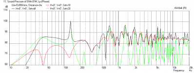
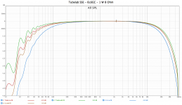
On the loudspeaker side Purifi’s initial offering is the PTT6.5W04-01A 6.5 inch woofer, a design that reduces distortion by tens of dBs while remaining linear to extreme excursion levels. This promises to allow bass depth with low midrange distortion that is normally the providence of large speakers using 12 and 15 inch woofers in jumbo multi-cubic foot boxes to be had from a ½ cubic foot / 15 liter enclosure 2-way system.

Purifi’s PTT6.5W04-01A is manufactured in Denmark. That is a good news bad news situation. Good news is for decades Denmark and Scandinavia have been a primary source of state of the art loudspeaker drivers and with European manufacturing by this team quality is a given. The downside is price, it does cost to manufacture in Europe, in this case $250 to $350 per driver depending on where one falls on the price breaks. So let us band together and save some dollars.

Purifi conducts all of their business in Danish krone, 1 Danish Krone equaling approximately 0.15 United States Dollar. As of this posting date cost in Danish krone and US dollars are as follows. These prices do not include shipping.

PTT6.5W04-01A Woofer Quantity based pricing table

Min__Max__Unit Price DKK__Unit Price USD
1____3_____2,329.00______$349.35
4____5_____2,108.00______$316.20
6____7_____1,871.00______$280.65
8____8+____1,663.00______$249.45

PTT6.5PR-01A Passive Radiator Quantity based pricing table

Min__Max__Unit Price DKK__Unit Price USD
1____3_____844.00________$126.60
4____5_____761.00________$114.15
6____7_____672.00________$100.80
8____8+____593.00________$88.95

Obviously if four or more of us commit to a pair of woofers each we can access the 8 pieces and above price break saving $150 to $200US on a pair. The exact savings depending on shipping costs, which I intend to pass on at cost. There will be no markup on this effort, I am donating my time to encourage fellow early adopters. That time will primarily be breaking the big shipment from Denmark into individual pairs, re-packing, and shipping onto the group members. Alas, to access the 8 and above price the shipment must be to a single address so a second shipment within N. America is required. I do have a commercial shipping address, which gets us a discount from Purifi’s shipping service DHL and avoids porch pirate worries.

Thanks to Purifi’s web store we can see exact cost to land a group buy to USA. The following tables show those costs as of January 2020 with shipping to Oklahoma. The first table for a group order for four of us to get one pair of PTT6.5W04-01A woofers each, eight drivers total. The second table shows the cost to buy a single pair of drivers as a comparison.

PTT6.5W04-01A Web Costing Group Buy

Item_____Quantity___Unit Price DKK__Unit Price USD___Order Price DKK__Order Price USD
PTT6.5-04___8_______1,663.00_______$249.45_________13,304.00______$1,995.60
Shipping____1_______1,312.00_______$196.80__________1,312.00_______$196.80
__________________________________totals__________14,616.00______$2,192.40

Unit cost group buy landed in USA $274.05
Pair cost group buy landed in USA $548.10

PTT6.5W04-01A Web Costing Individual Buy

Item_____Quantity___Unit Price DKK__Unit Price USD___Order Price DKK__Order Price USD
PTT6.5-04__2________2,329.00_______$349.35_________4,658.00________$698.70
Shipping___1__________622.00________$93.30__________622.00_________$93.30
_____________________________________totals_______5,280.00_________$792.00

Unit cost individual’s buy landed in USA $396.00
Pair cost individual’s buy landed in USA $792.00

Bottom line is buying individually a pair cost $792 vs. as a group $548 + Oklahoma to you shipping.

If you want to join this group buy reply to this thread and send me a personal message with contact info. I plan the process to proceed as follows:

1. Recruit enough participants to qualify for quantity 8+ pricing.
2. Close participation in initial group buy.
3. Check costs to buy woofers (and passive radiators if anyone orders those) and shipping costs Denmark to Oklahoma, communicate each individual’s total to participants.
4. Participants pay using PayPal to group buy organizer. Your PayPal receipt will state “Expected delivery time 6 – 8 weeks”, I will try to beat that, most of that will be determined by Purifi’s build time and shipping including clearing USA customs.
5. When all funds arrive order is placed with Purifi. Be aware Purifi states “Note that this product is made-to-order. Expect approximately 4 weeks delivery time.”
6. While Purifi builds and ship woofers group organizer will prepare boxes and packing for shipping leg within North America.
7. When shipment arrives in Oklahoma group organizer will break down into shipments to individual participants, determine cost, and communicate to each participant their North American final leg shipping cost.
8. After participant pays their individual within N. America cost group organizer ships their order.
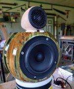
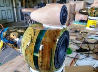
9. Woofers arrive individual participants’ workshops where they are installed in boxes. Jaws drop, sonic bliss ensues.

Obviously at this level of cost to entry we have a classic case of it is expensive to participate at the cutting edge of technology. I expect the cost to entry will surface individuals with the commitment and means to participate. Given that one should not need to say, yet out of an abundance of caution I will; do not be a wimp! Once you commit do not try and back out! This is not Amazon with free returns, you buy via this group buy and they are yours. If ultimately the sound is not to your liking it is on you to store, scrap, or sell them on. I do not intend to allow that reality to give Purifi a pass on their quality obligation to deliver product as specified to us. What I will not allow is audiophile wimp buyer’s remorse with excuses like “I don’t like how it looks”, “I’ve decided to go a different route and want a refund to help fund that project”, or “upon audition they lack a certain air and “je ne sais quoi” my incredibly refined hearing cannot do without”.

I am excited the Purifi PTT6.5W04-01A is a true breakthrough, something rare in such a mature century old technology. I hope you will join me as one of the first to explore it.

Felt to help with baffle diffraction

Has anyone on here experimented with felt in reducing or eliminating baffle diffraction? I have a situation where I have to have a large baffle and was thinking of just using a ton of felt covered in grill cloth or something to eliminate the diffraction. Would having the baffle back about an inch from the speaker front and fill that gap with felt, would that help? This is what I am currently thinking as otherwise it would be a wide baffle of about 16" x 29" wide open baffle.

The speaker is going to go into a cabinet so I would think a large baffle would be better than a slim speaker in a cabinet, yes? Maybe this should be in Construction Tips? If so feel free to move!

Bxi2610d mistake

I tell you that what could have been a simple repair I have complicated by an oversight, I was repairing a hifonics bxi2610d amplifier which had damaged the source mosfets and some of the audio stage, so as not to make it too long I reached the point of I had an oscillation signal in the 4 banks of the audio stage mosfets, but in one of the banks the only irf9640 got warm , when checking the signal with the scope was a bit strange. The signal was not completly square it has a peak of correct voltage but almost inmediatly, it fall at about 2 volts peak to peak, looked like a continuación of square wave and sawrooth signal.

Using car speakers in home HiFi setup

Hi all

I was hoping to get some opinions on using car speakers in a home HiFi setup. The reasons I want to do this is purely the range available, cost and ease of acquiring car speakers - I want to go as slim as possible.

The speakers I'd like to use are either the Infinity Kappa series or the Blaupunkt ultra-flat OD series. Whichever I decide to go with, each cabinet will have its own amp and crossover.

Also, I read on the DIY High End website (http://www.diy-high-end.com/amplifier/) that mounting low frequency speakers back-to-back improves sound quality, has anyone tried this?

Many thanks.

Mo.

More 6158/13D3

Coincidentally, I have just started testing a new amplifier.

This is balanced like all my stuff.

It uses a 13D3 input diff pair. This is unusual in that I am flying in the face of theory, because whilst it has a conventional cascode SS current sink at the bottom, it has active loads on the anodes. Most people say that this will not work as the sources and sink will fight each other.

Well it certainly works at DC; it is passing more or less the design current.

The next stage, is a pair of D3As, as pentode cathode followers, which will be DC coupled to the output valves, a quartet of 6CK4s.

I am having a bit of trouble testing because obvioully I have a -ve supply and am having difficulty with getting the voltages right in testing without the output stage. Really I need two adjustable power supplies; and I have only one variac!

More later.

7N7

Pete Millets 50W monoblock amp issue

Hello all: Having an issue with one of the mono block that I built from P. Millets schematic and was wondering if anyone can shed some light on the issue. So I built the P.Millet 50w mono block engineers amp using his board and followed the schematic exactly as prescribed and the amp worked great. I had it in storage for 4-5 months and recently hooked it up, checked the bias (running it between (350-425mV) and everything seemed in spec. Then I started hearing intermintent static on one channel and notice bias voltage jumping past the 500mV and beyond. I check all the tubes and they were good. So my question is what could be causing the spike in bias voltage with the static to the speakers? I looked at schmatic and was thinking it could be the IXCP10M45 current regulator? This seems to occur around after 30 minutes of playing, I have also traded out all tubes and problem still persists. Thanks for any assistance in this matter

Room gain simulation in Winisd

Hello,

i never build a enclosure yet, but have been studying and simulating in winisd some possible projects with two types of speakers i have

i always design the box the way i could get the more bass possible, thinking that will be the best final response of the enclosure im my room

but i saw the Scott Lindgreen video in NWAS 2018 saying that he consider the room gain when designing a speaker letting the bass part of the spectrum a little shorter then desired because when in the room the bass will be reinforced and the box will deliver the desired full response

i find this video where he show how to estimate the room gain while desigining the speaker, so we can see if it will match our desired final response when playing in the real life of our rooms

Login to view embedded media
my question is:

this method is ok to do?

because i am a fraid i will design a speaker with the most bass possibel in the winisd and when palying in my room it will sound boomy or not good because the room gain that i dont consider in the project

thank you

Impedance mismatch: Source output impedance is high compared to amp input.

Hi
I be been using a DAC/preamp to successfully drive my Class-D power amp, which has a 10k input impedance.The DAC/pre has an output impedance around 200 ohms.
I also have a pair Dayton DSP-LF units that i'd like to insert to analyse and room correct the lov end of my speakers; which should improve bass sound, since my tower speakers are placed out into the room for best stereo image.

However, I discovered the DSP-LF specs say its output is 1v and 10k ohms output impedance.
.
Using a 6ft shielded interconnect between the DSP and my power amp, if source and load are the same impedance, how would that affect the audio signal, and would there be a negative impact on the sound?
Alternatively, I could run the 6ft cable to the DSP, which could sit right at the amp...
Thanks

Decware DNA Horn

In the Foam Core thread, I posted the Decware DNA BLH to see if there was any interest in doing a DIY version of it in easy foam core. See post here: Foam Core Board Speaker Enclosures? - Page 175 - diyAudio

Here is Bcmbob's build in XPS foam:
347516d1368051659-decware-dna-horn-20130508_181632-jpg


There is some interest in proceeding with it as I can see that as of now, there have been 32 views of the approximate dimensions that I posted as a pdf plan here: diyAudio

The DNA was designed for use with the now discontinued TB W5-1880 driver. In the interest of trying this design out in FC on a budget, I spec'd the following cheap 5 in aluminum cone driver from MCM: MCM Audio Select 5'' Aluminum Cone Woofer | 55-1870 (551870) | MCM Audio Select

I simulated the DNA in AkAbak with the following horn expansion profile that I derived using dial calipers from the drawing (13 segments total with the first one being the throat leading to the main horn passage. The throat width is equivalent for a 2.5 in dia hole.)

Code:
| Define Horn Segments (need to multiply by Width for area, dims in inches * 0.0254 in/m): S_Throat, S_Mouth, Length

	S1T=0.70*0.0254;	S1M=0.701*0.0254;	L1=0.18*0.0254;
 	S2T=0.64*0.0254;	S2M=0.76*0.0254;	L2=5.09*0.0254;
	S3T=0.76*0.0254;	S3M=1.30*0.0254;	L3=5.09*0.0254;
	S4T=1.30*0.0254;	S4M=2.01*0.0254;	L4=16.08*0.0254;
	S5T=2.01*0.0254;	S5M=2.88*0.0254;	L5=6.03*0.0254;
	S6T=2.88*0.0254;	S6M=2.89*0.0254;	L6=1.47*0.0254;
	S7T=2.88*0.0254;	S7M=4.02*0.0254;	L7=3.35*0.0254;
	S8T=4.02*0.0254;	S8M=4.29*0.0254;	L8=1.30*0.0254;
	S9T=4.29*0.0254;	S9M=4.30*0.0254;	L9=2.68*0.0254;
	S10T=3.83*0.0254;	S10M=4.52*0.0254;	L10=1.45*0.0254;
	S11T=4.52*0.0254;	S11M=6.16*0.0254;	L11=7.64*0.0254;
	S12T=6.16*0.0254;	S12M=7.41*0.0254;	L12=3.40*0.0254;
	S13T=7.41*0.0254;	S13M=15.68*0.0254;	L13=5.23*0.0254;

The main driver chamber was estimated to have a volume of 16.1 liters, and the throat hole leading from the chamber to the start of the horn passage is assumed to be 2.5 in dia.

The result of the simulation for the DNA with the W5-1880 driver appears to go down to about 30 Hz in bass extension - not bad. This is for the speaker placed with baffle 18 in from rear wall and 4 watts of power with listening position at 3 meters away from front baffle.

For the cheap $13 MCM drivers, I had to reduce the driver chamber volume by 6 liters to 10.1 L and this provided a much better response due to the much stiffer suspension (smaller Vas). With this driver, the bass shelf is a little tilted but nonetheless smooth and goes down to 40 Hz. The last plot shows the driver cone displacement for the MCM 55-1870 driver at 4 watts. With appropriate stuffing in the main driver chamber the resonances and peaks should be reduced significantly - so ignore the sharp peaks when viewing the plots. I still have not figured out how to implement damping/stuffing in AkAbak.

The design appears to a good one and I think worth pursuing even with the budget driver - 40 Hz extension and it appears that there may be enough bass gain to avoid using a BSC.

Some recent plans from DimeStore Dynaco:
attachment.php

Attachments

  • DNA-BLH-W5-1880-3m-4watts-good.png
    DNA-BLH-W5-1880-3m-4watts-good.png
    31.8 KB · Views: 2,934
  • DNA-BLH-mcm55-1870-3m-4watts-10liter-good.png
    DNA-BLH-mcm55-1870-3m-4watts-10liter-good.png
    31.7 KB · Views: 3,371
  • DNA-BLH-mcm55-1870-3m-4watts-displ.png
    DNA-BLH-mcm55-1870-3m-4watts-displ.png
    23.1 KB · Views: 2,790

Proac response one crossover

Hi everyone
i am new to this forum, and i would need help if any expert can do it.
I would need the crossover diagram, with the component values indicated, for a pair of proac response 1 (the first series of 1990/91, the one that had external crossovers.)
I can't find any information on the web about these particular crossovers, and i need to replicate the original circuit and values.
if there is anyone who can help me i would be very grateful.
Thank you
Luca

Mark Audio Alpair 12P with current drive

I got an idea about a speaker & amplifier combination. I thought it would be wise to ask if others have experiment with this.

So my idea is to build a system with these features:
  • Mark Audio Alpair 12P full range speaker drivers (two)
  • Approximately 3 cubic feet or 85 litres sealed cabinets (two)
  • Quite tightly muffled box cavity with plenty of teared cotton ribbons
  • A current-drive made with a transconductance amplifier or by other means
  • No other drivers or any passive filters
  • Decent cables, nothing fancy
I already have the two sealed boxes made of thick chipboard. Purchasing the drivers and building amplifiers would be the next big steps.

I got few questions also:
  • Would the mechanical damping flatten the resonance enough or should I also prepare to build a filter to take care of that low frequency resonance?
  • I thought about covering the speaker boxes with acoustic cloth (speaker grille cloth). The boxes are right-angled. I would cover each box with snugly fit cloth hoods. Anyone done this and does it work well?

Understanding Sympathetic Resonance?

Can somebody explain this to me please? Next to my main set up is a glass-fronted cabinet. The sub next to it causes no problems. 20 feet away in the opposite corner of the room, on a separate system, my desktop speakers rattle that same cabinet. Why does this happen? The desktop speakers are small units with 6.5" woofers - they do not produce earth shattering bass.

SigmaStudios- DSPB-K DSP Kernel Board and DSPB-KE Kernel DSP Expansion 2-In 3-Out

Picked up Dayton Audio Version-

Using their provided "project" and I get a lot of static even with external amplifier off.
I've tried my AVR and 3 separate power amps as power and still static. Ive tried different USB power- and leaving the programmer plugged in and not plugged in. This is by far the cheapest solution for redoing my theater as active- so trying my best to get this to work, But that static is just horrid

Trying to make 3 way crossover- for HT

Login to view embedded media

Attachments

  • sigma project.PNG
    sigma project.PNG
    22.2 KB · Views: 142

For sale: PhiDecaDAC with 7th order filter

For sale 1 PhiDecaDAC with 7th order filter. Asking $50. Buyer pays shipping cost. I'm located near Seattle WA.

I'm only selling because I built my own DAC using TI PCM1794. I'm proud of my work, so I've replaced the PhiDecaDAC with my own in my system.

Here is the page with all the info about the PhiDecaDAC:
https://www.diyaudio.com/community/threads/phidac-hex-kits-with-pre-built-filters.354799/

PhiDeca DAC needs a 15V regulated power supply, max current draw is 160mA. A 500mA rated linear wall-wart is suggested.

Attachments

  • IMG_9749.jpg
    IMG_9749.jpg
    398.5 KB · Views: 136
  • IMG_9750.jpg
    IMG_9750.jpg
    459.9 KB · Views: 139
  • IMG_9751.jpg
    IMG_9751.jpg
    342.8 KB · Views: 133
Projects by fanatics, for fanatics
Get answers and advice for everyone wanting to learn the art of audio.
Join the Community
507,772
Members
7,887,947
Messages

Filter

Forum Statistics

Threads
406,207
Messages
7,887,947
Members
507,772
Latest member
Hypertone