Hi guys,
I don't suppose someone could help me out with the wiring on the stepped attenuator I'm building?
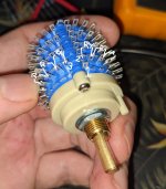
I've attached a photo of the unit, and the resistor values i bought are for a series attenuator, whereas most of the guides online seem to be for the shunt type.
If I attach my meter between pin 1 and 3, the resistance adds up in series from zero resistance upwards as i decrease the volume from max, or if i connect 1 and 2, it increases as i increase from minimum volume. And this has lead to a couple of questions.
1. where should my ground, signal in and signal out be attached.
2. should RX or RY be the largest resistor? (i'm using the 50k figures from https://www.goldpt.com/r_series.html so the 10.2k value is what I'm looking for confirmation on)
Thanks, Tim.
I don't suppose someone could help me out with the wiring on the stepped attenuator I'm building?
I've attached a photo of the unit, and the resistor values i bought are for a series attenuator, whereas most of the guides online seem to be for the shunt type.
If I attach my meter between pin 1 and 3, the resistance adds up in series from zero resistance upwards as i decrease the volume from max, or if i connect 1 and 2, it increases as i increase from minimum volume. And this has lead to a couple of questions.
1. where should my ground, signal in and signal out be attached.
2. should RX or RY be the largest resistor? (i'm using the 50k figures from https://www.goldpt.com/r_series.html so the 10.2k value is what I'm looking for confirmation on)
Thanks, Tim.
Attachments
seriously...this like wondering why a volume control is behaving in reverse and failing to understand why...
i hope this will help illustrate why...(increasing the resistance between the signal pin and ground increases gain..no?)

think it through at position 24 there's all that series resistance between the signal and ground (ie no attenuation) when you move (hopefully counter clockwise, depending on where you've applied or attached ground) toward position 1 your developing a short to gnd between the signal pin and ground....(the pioneers knew this but a few generations removed the internet short circuits the application of rational thought!)
so in effect shunt and series are congruent...
sorry Greg your link fails to elucidate the point.
i hope this will help illustrate why...(increasing the resistance between the signal pin and ground increases gain..no?)
think it through at position 24 there's all that series resistance between the signal and ground (ie no attenuation) when you move (hopefully counter clockwise, depending on where you've applied or attached ground) toward position 1 your developing a short to gnd between the signal pin and ground....(the pioneers knew this but a few generations removed the internet short circuits the application of rational thought!)
so in effect shunt and series are congruent...
sorry Greg your link fails to elucidate the point.

seriously...this like wondering why a volume control is behaving in reverse and failing to understand why...
i hope this will help illustrate why...(increasing the resistance between the signal pin and ground increases gain..no?)
View attachment 1114759
think it through at position 24 there's all that series resistance between the signal and ground (ie no attenuation) when you move (hopefully counter clockwise, depending on where you've applied or attached ground) toward position 1 your developing a short to gnd between the signal pin and ground....(the pioneers knew this but a few generations removed the internet short circuits the application of rational thought!)
so in effect shunt and series are congruent...
sorry Greg your link fails to elucidate the point.
Electronic circuits aren't my strong point despite years of trying, I'm on the spectrum and some things just don't click in my brain.
I'd really love it if you could just answer the 2 questions I had instead of implying I was stupid and regurgitating what I had already read and failed to confidently understand for the past few days.
The joy of forums over say Facebook groups is that knowledge can be easily found for years to come through Google, and you could be the guy that helps clear things up for hundreds of people. just answering my questions instead of giving the self grandiosing lecture would have saved you a lot of time and typing and wouldn't have made you look like an ***; it's clearly an elementary question for you to answer.
One of my favourite things about my hobbies that I know an exceptional amount about is going out of my way to help and coach newbies, it brings a lot of joy, satisfaction and forged many friendships. Does it sometimes get tiring seemingly having to explain the same things repeatedly? Sure! But I still do it, because it's about the other person's level of confidence and ability, not mine.
If you'd like, you can go ahead and edit your original post into actually being helpful, and I can delete this post, and the forum can be a more friendly, welcoming and helpful place for everyone 🙂
not my fault you feel insulted and because this is across the internet how would i know that your on the spectrum??
it's a rather simple problem and yup it is frustrating to answer questions such as this...
"question 1 where should my ground, signal in and signal out be attached."
should be clear looking at the schematic. i'm not clear as to your reference to pins "one" and "three", i would have to assume from your description pin 1 is the start of the resistor ladder and where your ground would be attached, your pin 3 i would have to assume to be the wiper/moving contact which is your output (on the schematic it's merely listed as OUT), after that your input would be attached to pin 24 as per the schematic i supplied.
"question 2 should RX or RY be the largest resistor? (i'm using the 50k figures from https://www.goldpt.com/r_series.html so the 10.2k value is what I'm looking for confirmation on)"
after looking at the list of resistor values in the link you supplied, there's nothing designated RX or RY so i've no idea what your referring
to...if your building an attenuator to suit a 50k impedance 10.2K would be the final resistor value in the ladder, and yes i'm not certain if that's the confirmation your looking for?
i don't know if any of this has helped but i'll gladly continue to as you say "look like an ***" if in the end i succeed in helping you get this!! OK?
ok now that i've looked a this picture in expanded form i can see your pin designations (which weren't seen viewing it as a thumbnail)
and i could be wrong but what you've marked as 1 i think is the moving wiper (or OUT) if the attuentor is rotated fully clockwise and you get continuity between it and 2 that would be position 24 per the schematic, conversely if you rotate it fully counter clockwise and get continuity between your 1 and 3 then your 3 is pin 1 per the schematic.
i hope that helps....my assumptions in post 7 where wrong!
Last edited:
I'm very confused as to how someone with so much knowledge and expertise as you proffer are failing to follow my diagram?not my fault you feel insulted and because this is across the internet how would i know that your on the spectrum??
it's a rather simple problem and yup it is frustrating to answer questions such as this...
"question 1 where should my ground, signal in and signal out be attached."
should be clear looking at the schematic. i'm not clear as to your reference to pins "one" and "three", i would have to assume from your description pin 1 is the start of the resistor ladder and where your ground would be attached, your pin 3 i would have to assume to be the wiper/moving contact which is your output (on the schematic it's merely listed as OUT), after that your input would be attached to pin 24 as per the schematic i supplied.
"question 2 should RX or RY be the largest resistor? (i'm using the 50k figures from https://www.goldpt.com/r_series.html so the 10.2k value is what I'm looking for confirmation on)"
after looking at the list of resistor values in the link you supplied, there's nothing designated RX or RY so i've no idea what your referring
to...if your building an attenuator to suit a 50k impedance 10.2K would be the final resistor value in the ladder, and yes i'm not certain if that's the confirmation your looking for?
i don't know if any of this has helped but i'll gladly continue to as you say "look like an ***" if in the end i succeed in helping you get this!! OK?
Pins 1, 2 and 3 are clearly labelled on the photo I attached, I also explained how they are functioning, as are spaces for resistors RX and RY, did you open the image, I can understand if you weren't able to follow it if you just looked at the thumbnail. And I'm not sure why you even needed to look at the list of resistors, all I'm asking is where the largest is placed assuming I want the volume control to be clockwise to increase volume on an audio/log taper? With loudspeaker crossover design a large resistor value can either decrease amplitude less or more than a smaller one, so knowing which end of the sweep has the largest value on a log taper isn't a cut and dry answer to someone unfamiliar with a part with the signal path hidden inside the unit.
No, I'm not able to follow a schematic (of which I have very little knowledge in general) onto a part with all the paths hidden inside.
No, your answer was not any help.
If you could have just look at the image and state;
pin 1 is in/out/ground
pin 2 is in/out/ground
pin 3 is in/out/ground
You want the 10k resistor on RX/RY
That would be an immense help, and I'd then understand the schematic instantly. If there's any critical information missing from what I've provided, you could let me know of that too and I'll see what I can do to fix that.
And I didn't expect you to know that I was on the spectrum, I was expecting a simple answer to a simple question answered politely, and if you wanted to expand on the answer with whatever you wanted after, that's cool too. I don't enjoy admitting and explaining to people that I find some things incredibly difficult, that they may find simple, Mensa verified my IQ at 155+ on the SB scale, so I'm sure there's plenty of things that I find elementary that you or others may not, but I'd never dream of talking down to them in the manner you have with myself.
Thank you, that's of great help. I hadn't seen this reply before starting my last reply and posting it.View attachment 1114864
ok now that i've looked a this picture in expanded form i can see your pin designations (which weren't seen viewing it as a thumbnail)
and i could be wrong but what you've marked as 1 i think is the moving wiper (or OUT) if the attuentor is rotated fully clockwise and you get continuity between it and 2 that would be position 24 per the schematic conversely if you rotate it fully counter clockwise and get continuity between your 1 and 3 then your 3 is pin 1 per the schematic.
i hope that helps....my assumptions in post 7 where wrong!
well let's verify what's what and move on from there.
if my last assumptions are correct then RX would be 40.2 and RY would be 10.2K
i did indeed fail to look at the thumbnail...i'm old and my eyesight is bad...we all have our shortcomings...apologies again for coming across prickly earlier!
from the picture it does appear to be a 4 pole device are you using all 4 or just two for stereo?
Last edited:
no worries dude, you've fully redeemed yourself by helping out and admitting you made a mistake. and my apologies for maybe reacting a bit quickly.well let's verify what's what and move on from there.
if my last assumptions are correct then RX would be 40.2 and RY would be 10.2K
i did indeed fail to look at the thumbnail...i'm old and my eyesight is bad...we all have our shortcomings...apologies again for coming across prickly earlier!
Hope you have a good day!
- Home
- Source & Line
- Analog Line Level
- Help with wiring series stepped attenuator