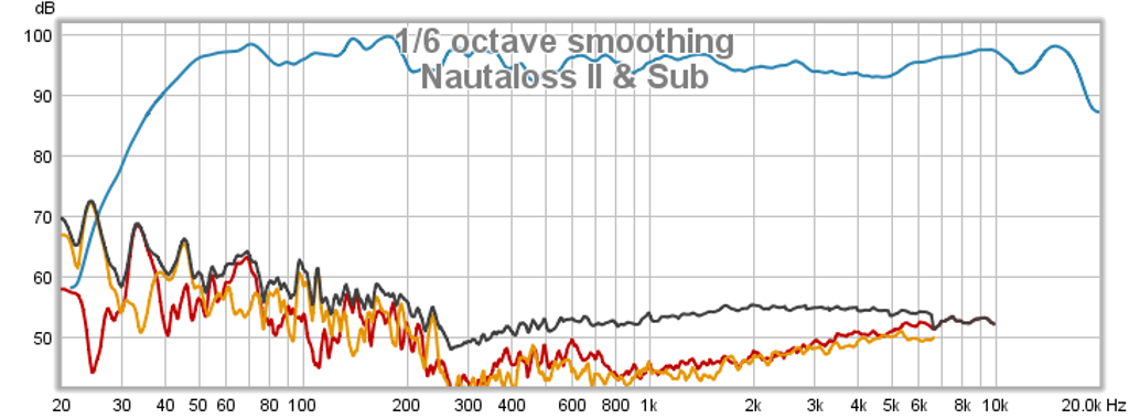
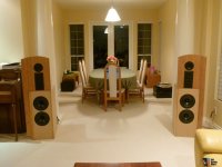
Edit - Jan 12, 2014: The bottom line - here is the final in room response and THD of the Nautaloss II Reference Monitor with Subwoofer and DSP crossover. -3 dB points are 42 Hz to 18 kHz, THD is between -30 dB to -40 dB at an average of 96 dB SPL at the listening position:
I started this speaker in the Foam Core thread (
http://www.diyaudio.com/forums/full-range/223313-foam-core-board-speaker-enclosures-203.html#post3734447) on somewhat of a whim as I was inspired by the namesake speaker and wanted to try a quick and cheap foam core version to see what it may possibly sound like. (Anthonybisset is credited for coining the name)
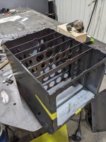
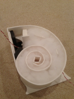
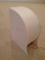
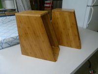
Usually, I model and simulate a speaker pretty thoroughly before a build, but in this case, the concept was to have a spiral sealed-TL so I thought it would not be as critical as the point was to absorb the back wave and provide bass extension to as close as possible the natural fs of the driver in an open baffle. Eschewing sims, I began directly with a pencil sketch on a piece of foam core and drew an approximate 36 in long spiral that fit in a 12 in tall x 9 in deep envelope (to keep a reasonable size for a bookshelf or desktop speaker).
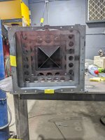
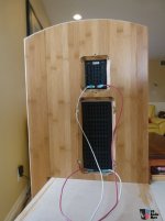
I then added some internal bracing at 90 deg intervals for the first 360 deg.
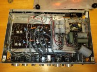
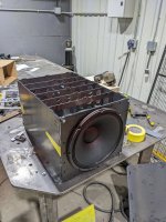
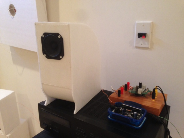
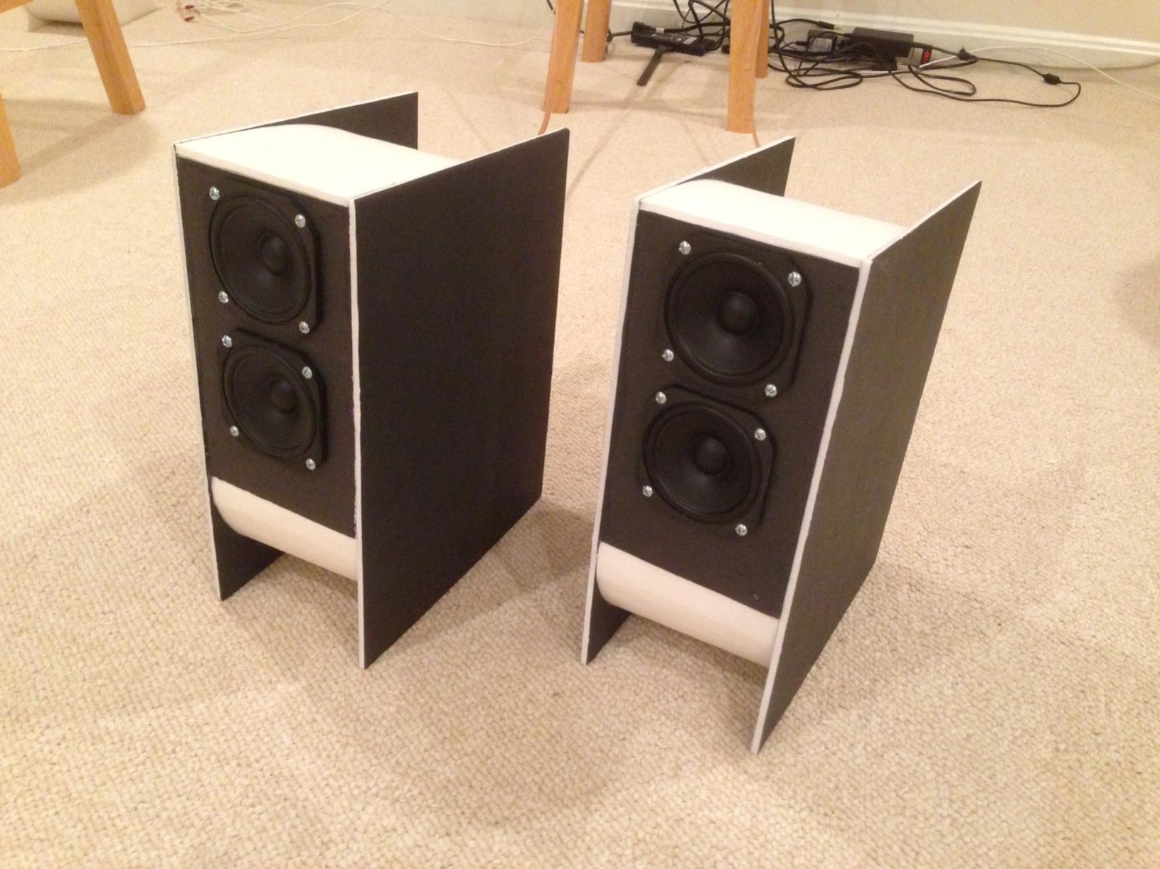
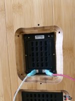
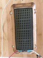
Then put in some speaker wire and added pillow stuffing. I glued some open cell foam around the flat areas near the front - the idea being to avoid any flat surface that could produce a back reflection or resonance that might show up on the front side of the cone. I then capped it off with a combination of hot melt and pva glue. Let it dry for 6 hours then installed the Vifa TC9FD driver.
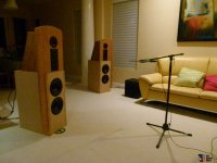
First sound listening impressions: wow! - the clarity, transparency, and overall balance was just amazing. Although it has no bass below 150 Hz really given that the fs is 120 Hz, however this is perfect for use with a helper woofer or subwoofer crossed at about 200 to 300 Hz. The speaker really sounds good.
To confirm my suspicions that the speaker was indeed very even in character, I set out to measure it using a Panasonic WM61A mic capsule wired to my laptop soundcard. This works well below 5kHz but unfortunately cannot get anything above 6kHz due to what appears to be a low-pass filter built in to the mic input as it was designed for web chats.
The initial measurements really shocked me by how flat it was from 300 Hz on up. The measured THD was very low - I would say probably rivaling some of the very best full range drivers out there costing many times more. However, there was this pesky drop off in the response that made a cliff at 300 Hz. After scratching my head and looking at some sims in Akabak, this drop is a room-effect (distance to walls and floor).
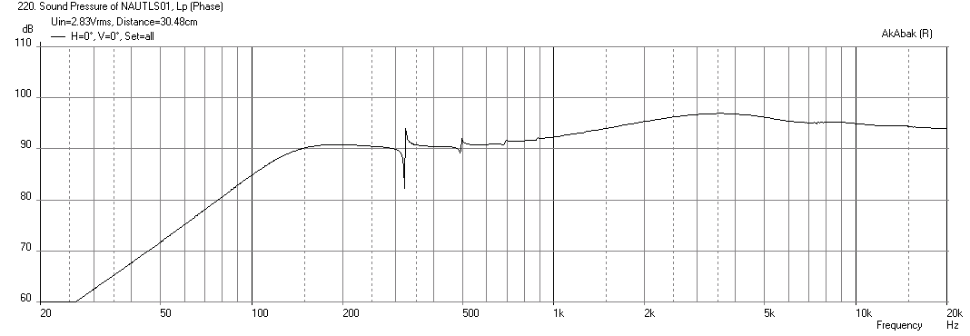
Here are sims without room reflections:
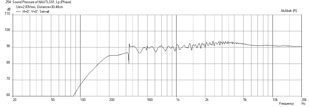
Here is the sim including rear wall at 50 inches and floor at 45 inches high:
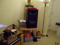
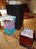
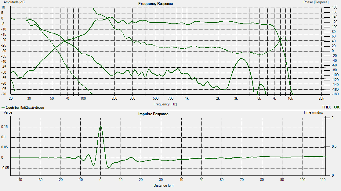
I then repeated the measurement with the same driver in an open baffle at the same location and also saw the same 300 Hz cliff, confirming that it is not the speaker enclosure (nor driver break-in) that caused this effect. The next step was to orient the speaker so that the room walls were 45 deg and I added a sheet of open cell foam and a pillow on the floor below.
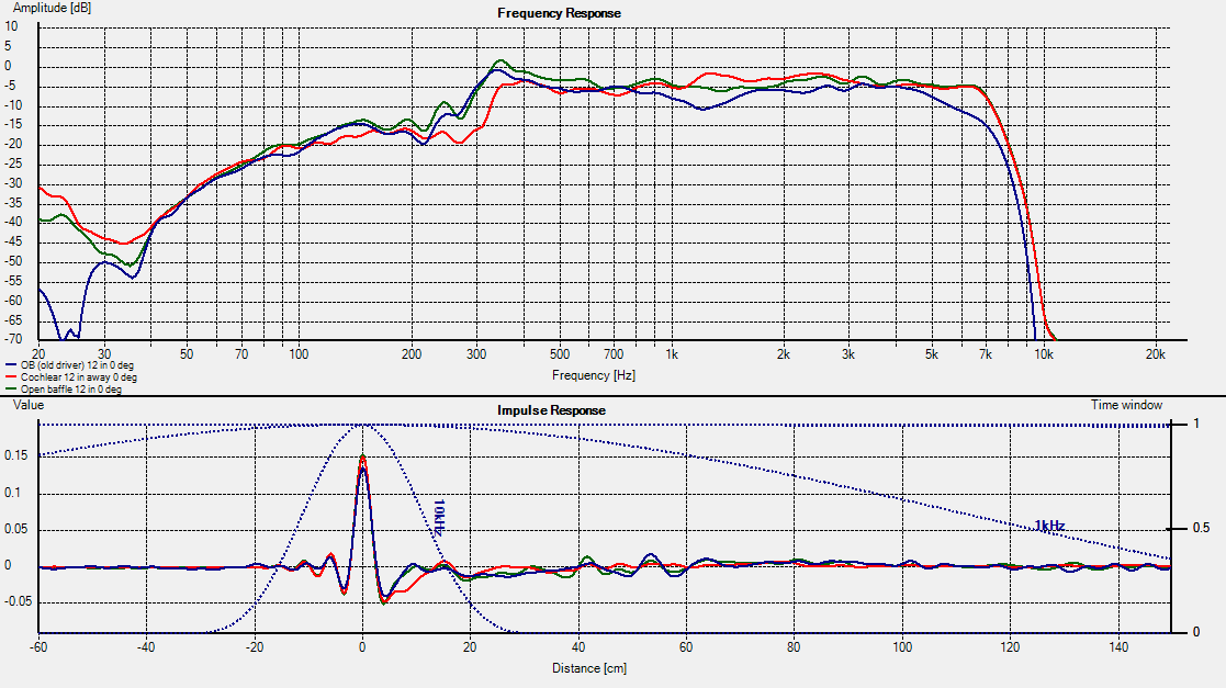
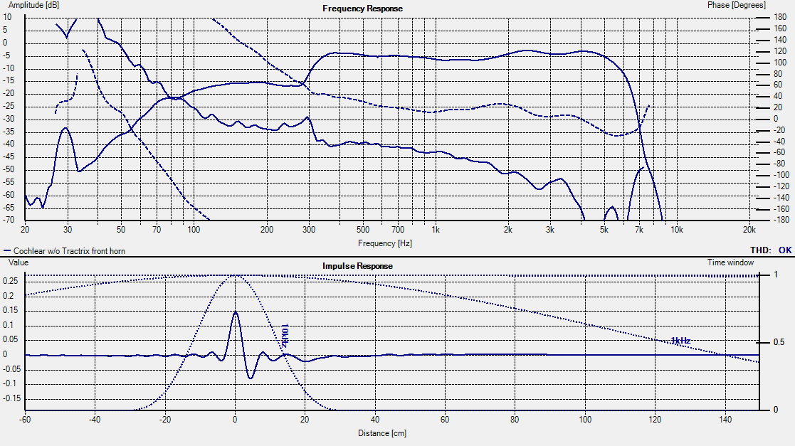
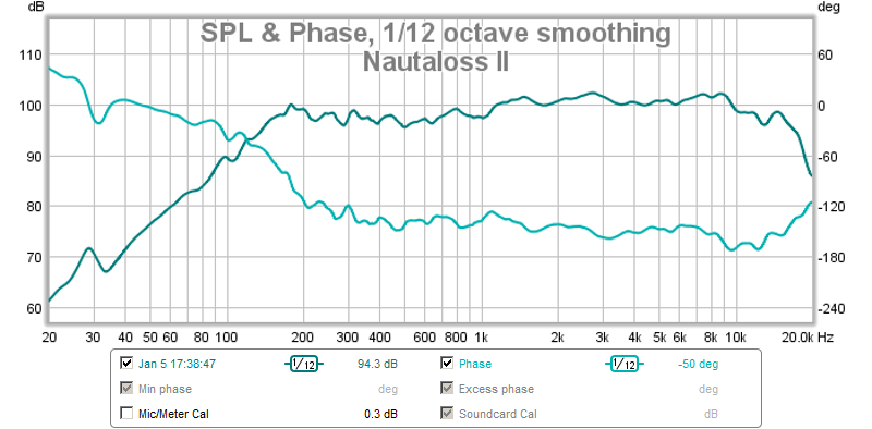
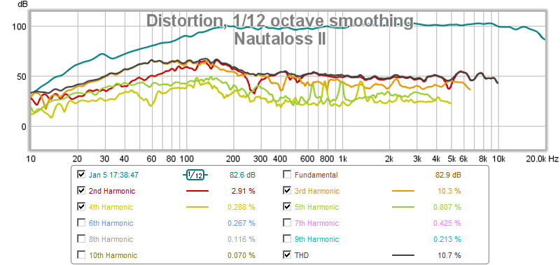
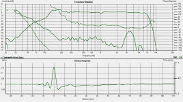
The new measurements with the room effects, now mitigated, produced a very nice frequency response curve from 150 Hz on up (I will assume that above 6 kHz the speaker performs closely along the manufacturer's published data - which is actually very flat for a full range driver). Note that from 200 Hz on up the variation in SPL is only about +/ 2 dB and the THD is typically below -50dB with a wide loaf shaped bump at about 3kHz but still very respectable. The phase variation over this range is also very linear and relatively flat. I believe, all these things point to a speaker that will sound very coherent and accurate. Finally, looking at the impulse response function, we see that this speaker has an almost ideal response function that is very clean and short with minimal ringing. This might be described as tight, clean, or fast.
Given that this speaker appears to measure very closely to an OB, I would say that the spiral is doing its job of acting like an infinite cavity by absorbing all the back wave without any reflections.
This speaker can be constructed from exactly 1 sheet of $1 foam core stock and the Vifa driver costs $10. These are not the most efficient drivers but at 85 dB for 2.83V input, they are not bad for near field use. The frequency response flatness, the low THD, the linear phase variations, and the near ideal impulse response make them perhaps one of the best values for a near field "monitor" from 200 Hz to 20 kHz.
Finally, here is the measured response with the effect of the room wall/floor bounce cancellation effect mitigated:
It is a fun and easy quick build. Give it a try if you are looking for a cheap but accurate speaker. This will make an excellent top for FAST system.
Cheers,
Xrk971
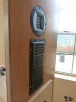
*** Edit (Jan 5, 2014) *** added measurements from dual driver Nautaloss II (including waterfall and spectrogram).
Nautaloss II Measurements are here:
http://www.diyaudio.com/forums/full-range/247598-nautaloss-ref-monitor-11.html#post3766222
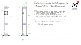
Here is the pdf plan for the Nautaloss II
http://www.diyaudio.com/forums/full-range/247598-nautaloss-ref-monitor-19.html#post3788028
Freq Response is very flat from 200 hz to 18 kHz:
THD is -50dB!:
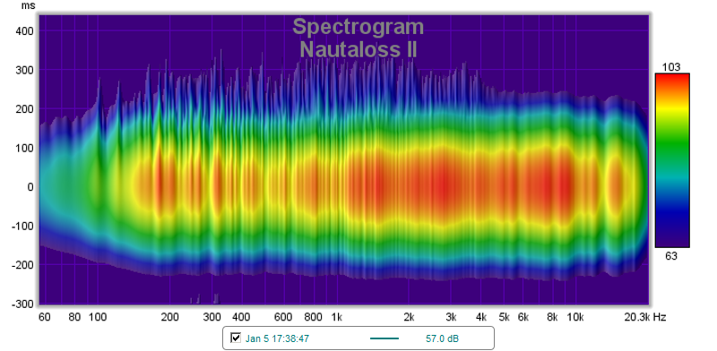
Spectral Decay: