Retired P.A. guy triggered by D.I.Y. boombox

Story time,
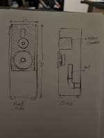
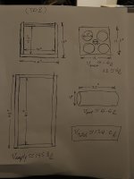
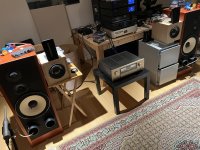
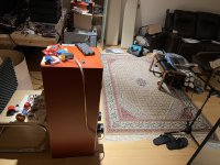
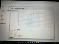
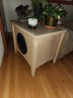
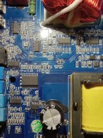
Here I am looking around at my dream shop (cabinetry, wood and metal fab) wondering how to have a little fun on the weekends. I retired mostly from live audio and recording industry about 6 years ago. My new business partner is talking about experiences he had with old school Turbosound and L-acoustic rigs as if he could remember the sound quality compared to modern stuff. I have acquired a little piece of land on which a bunch of audio tech, friends and family gather for fireworks & BBQ when the touring schedules are permitting it. I used to rent an AC generator and a PA system (like Nexo M6 / RS18) for those events but soon find out it was much overkill for most of the time since the jam bands don't even make it to the event sometimes. We end up using 10% of the SPL for ambiance music and karaoke our way through the night. Me and the boys then started messing around with car audio to replace those little JBL Bluetooth mini boom box that are just no fun at all besides for a crowded beach. That's when I found out about little tinny all integrated class D amps from China that run on 24v and have a sub output with adjustable low-pass filter. Since I had zero expectations for the quality of my 35$ by-amp system, I ordered the cheapest 4" car coaxial speakers and 6,5" subwoofer from amazon, watched a couple of car audio subwoofer maker videos and installed WinISD on my computer. That's how I found out how difficult it is to scale a box design for a smaller driver... I ended up with a baffle arrange at 90° and two different ported chambers on each side. One was 42,5L and the other 13 L. I made the ports long and narrow so I could tweak them by jamming wood panels in them to adjust the tuning. My old Smaart program was useless since I was metering the room as much as the box. (Even in a 40' x 40' x 16' garage!) I then checked if the impedance by frequency curve from WinISD was matching my observations and it was off by 3 Hz at both peaks. I took that result for a win even if I lack the knowledge to compare but one thing is for sure, I was hooked to building my own speakers. I then found out that the little port the software told me to put on my boombox top boxes, in relation to the volume, was really giving the boost at around the same frequencies the software was predicting. They don't sound good, but still, they flatten the response. Smaart was helpful in that range. The boombox perform well enough that the boys now want to make me listen to their last recording mix after a couple of beers. I made two other copies for friends who use power tool batteries as PSU and they’re still going strong. I even solve the karaoke thing by using a little 9v premp and mixer.

I now want to learn more about physics, driver parameters and simulation tools so I can figure out more stuff to build and have fun with especially since the fabricating is almost instantaneous for me. (Materials in stock, CAD, CAM, CNC router, sheet metal, paint booth, industrial woodworking tools, cnc lathe & milling, etc.) I feel like a spoiled kid. For now, I'm more into DSP and sound over IP stuff to mess with as for my commercial and PA back ground but I will get to the HIFI stuff eventually I'm sure. My first order of business is a mini line array PA that will replace that first project. I saw 16 channel audio interface with dsp on each of them that are available for less than I toughed possible. To me, that means I can purchase Amp and PSU modules and fiddle my way to the LO-FI mini line array PA or Atmos territory.

Thanks for reading this, I'll be in the subwoofer forum asking about a silly 6,5" driver Mini Paraflex-C box design.
Long live this great forum!
  • Like
Reactions: ZMathers and stv

Where to get heatsink with flat bottom?

Excuse the basic thread/tittle but I have never really had to shop for a speciifc heat sink before!


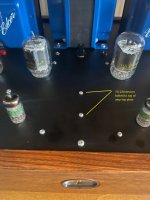
I need a heat sink for two TO-220 devices that are currently bolted to the top of a tube amp's top panel, the 4-40 bolts are 38mm apart. See attached pic.

Where can I find flat heat sinks from Mouser that I could drill and tap for 4-40 hardware?

Thanks!

Attachments

  • DCPP top panel.jpg
    DCPP top panel.jpg
    535.5 KB · Views: 154

Precision power D2000/1

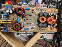
This amp came with 4 bad bipolar caps 10uf. I replaced with 2 22uf. Amp comes on and relays clicks. But as soon I give signal the relay starts to go off and on cycle. There is good output signal on one pin of relay. I tried to force relay to come on but then Amp tries to pull current and goes into protect. All the output mosfets have good gate oscillations.

Attachments

  • 20230405_170128.jpg
    20230405_170128.jpg
    818.2 KB · Views: 135

Help! I need a Hypex NC1200/500/400 signal cable...

I bought a 2nd hand nc1200 amp and want to redo the signal wiring. One of the signal cables is too short and the nampon wire was cut (?). I want to replace it and contacted Hypex- the cable is only $8US but they want $75US for shipping!! Does anyone have an extra they could sell me or know of a vendor who can supply one from the US?


Thanks for any help...

Spartan 10 high performance phonostage schematic

Hi Everyone,

It's been a while since I've been posting on this forum. I thought I might share the schematic and possibly PCB layout of the 'Spartan 10' phonostage, which I designed a couple of years ago and made into a commercial successful product, selling the last one in December 2022. Hopefully this counts as 'DIY' as I did indeed do it myself! Among other features it has...
  • Superb RIAA accuracy to ±0.1dB, absolutely none of the usual colouration found in almost all other phonostages that barely make ±0.5dB or worse
  • Spotlessly clean high frequency reproduction, through the use of limited high frequency negative feedback on the uncompensated input amplifiers
  • Very low distortion, from double-stage design that shares the amplification between two amplifiers stages
  • Low noise input amplifiers, optimised for real moving magnet cartridge impedance characteristics
  • Low frequency crossfeed, a unique switchable filter that cancels low frequency noise
  • Mono switching for getting the best out of mono pressings
  • 3rd order subsonic filtering from 22Hz
  • A fully linear split supply with start-up relay muting
It's a pretty straightforward single-page schematic, but works very well.

MF

Attachments

  • Like
Reactions: lordoff and vsmusic

RENESAS 2SK1058 2SJ162 Power MOSFET

The original Hitachi 2SK1058 2SJ162 have long disappeared from the market. NOS are very expensive and from unknown source. Some new MOSFET power amp design use the RENESAS 2SK1058 2SJ162 instead.

Currently, Mouser has the Renesas 2SK1058, but the 2SJ162 is out of stock. You can buy the pair from parts house in Hong Kong. Some even offer matched pair for additional cost.

What is the assessment of the RENESAS 2SK1058 2SJ162 in audio power amplifier construction?

Looking for ST70 amp OPTs exact core dimensions and winding dcr

Would any of you be so kind and give me the core dimensions and/or the dc resistance values of the original A-470 transformer?
I have the winding data but would need this additional data to be able to check if my attempt to calculate winding Rac/Rdc relation and proximity loss real/imaginare part is correct.

Complete data from ANY other OPT/amp combination would do as well.

Ideally, what i would need is the following:
Amp circuit diagram, specs, frequency response curve and measuring conditions
Core dimensions
Winding build up
Isolation build up
Primary and secundary turns per layer
Primary and secundary wire size
Primary DCR

Thank you for any assistance
Pete

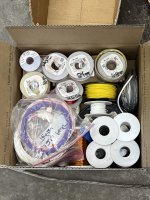
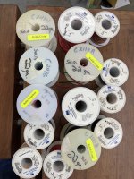
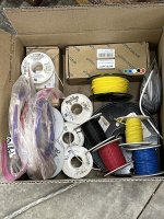
For Sale 14 pounds of various chassis wire 14 to 28 awg, magnet wire from 18 to 28 awg, shipping included

SOLD

Asking $200 or best offer, to include USA ground shipping.


I am clearing out some wire from the stockpile I will likely not be needing. Most of the wire is 600V wire, unless otherwise noted. Most comes on spools, but some of the PTFE finer gauge wire, and the KV 18 gauge wire are in baggies. Most is USA made, but the BNTECHGO is from China. I tried to estimate feet remaining on the spools, but I am sure I was conservative on all of them and you will get more wire than listed.

26 lots in total

CHASSIS WIRE

1- BNTECHGO 14awg, 20 ft each of black and red
2-BNTECHGO 16awg, 20 ft each of black, red, white, green and blue
3-Vampire cryo upocc 18 awg solid core, 10 ft each of red and black
4-Chinese 18 awg silicone insulated stranded, 20 kV high voltage, 25 ft of white, in bag
5-Milspec PTFE silver plated copper, 18 awg, 20 ft of green
6-Alpha wire, pvc over solid copper, 18 awg, 5 ft of black, 10ft of yellow and 10ft of green
7-Milspec PTFE over silver plated copper, metal spool, 18 awg 75 feet of white
8-Carol pvc over stranded 20 awg copper, 20 ft of black
9-Alpha 20 awg pvc over solid copper, 25ft of red and blue, 15ft of black, 10 ft of yellow
10-Alpha 20 awg PTFE over silver plated solid copper, 15 feet of white
11-Milspec PTFE over silver plated copper, 24 awg stranded, 30ft of white, 30ft of wht/brn, 30ft of red/grn all 3 in baggie
12-Milspec PTFE over silver plated copper, 26awg stranded, 30ft of purple, 30ft of wht/org, 30ft of wht/rd/brn, 30ft of wht/blk all 4 in baggie
13-Milspec PTFE over silver plated copper, 28 awg stranded, 30ft of purple, 30 ft of rd/wht both in a baggie

Enameled Magnet wire

1-Belden, 18awg, 30ft.
2-Remington, 18 awg, 10ft
3-Belden 20 awg, 100ft
4-Belden 24awg, 150ft
5-OCC 24 awg, on cardboard spool, 50 ft.
6-Belden 26awg, 400ft
7-Fay 26awg, 400ft.
8-Belden 28awg, 400ft

Packed in a USPS Large Priority Mail flat rate box.
IMG_0608.jpegIMG_0609.jpeg

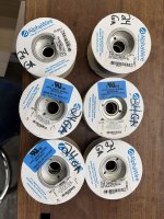
For Sale 7 pounds of 22awg and 24 awg poly coated chassis wire on spools, shipping included

SOLD

Asking $120 or best offer, including USA ground shipping


Wire spools I likely will not use in the near future, ready for their next home. 600v wire unless otherwise noted
All are poly/pvc coated, USA sourced wire.

22 awg

Carol brand

1-solid core, 40ft of brown
2-solid core, 40ft of white
3-solid core, 30 ft of white
4- stranded, 30ft of red
5- stranded, 25 feet of black

Alpha Wire
6-stranded, 40ft of black
7-stranded, 35ft of red
8-stranded, 1000v, 20ft of orange
9-stranded , 1000v, 20ft of gray
10-stranded, 1000v, 30ft. of brown
11-stranded, 1000v, 35ft of purple
12-solid, 1000v, 60ft of black
13-solid, 1000v, 60ft of red
14-solid, 1000v, 60ft of white

24AWG

Alpha wire, all stranded

15- 50ft of red
16- 50ft of yellow
17- 40ft of blue
18- 50ft of brown
19- 30ft of gray
20-20ft. of white

shipping in a USPS medium flat rate box

IMG_0610.jpegIMG_0611.jpeg
  • Like
Reactions: 2pist

USB powered MC phono preamplifier design

I recently got AT-OC9XML cartridge and I want to build op amp based MC only preamplifier that's powered from USB power bank. I decided that I use the circuit of Phonoclone from RJM Audio.

I could use DC-DC converter to step up the 5V USB voltage to 24V and use TLE2426 to split the rails for +12V and -12V.

But I'd like to keep it more simple and use rail to rail op amp. There aren't many op amps out there for audio use that are designed to be powered from only +5V. One such op amp is LME49721.

I came up with this schematic:

Screenshot_2023-04-06_20-56-24.png


I have lots of those USB-C connectors so that's what I'd use. R2 and R9 set the gain. AT-OC9XML has 0,4mV output so 180 ohm would give about 55 dB of gain for 0,7x line output.

As there's no negative voltage rail DC offset would be pretty high so fairly big output cap is needed. Before I start with the PCB layout I'd like some feedback about this. I'm an electronics hobbyist for many years but I'm new to audio circuits.

My idea is to make this SMD only build that would fit in slimline Hammond 1455B1002 (100x72x19mm) case.

1455b1002rb.jpg

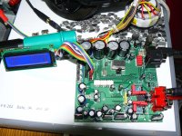
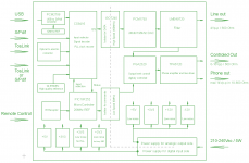
My second try on digital side

Hello,

This are my last DAC. The pictures are self speaking.

First pictures are with test boards single side and the last are with the finished pcb, double side. The last one it is the block diagram.

Attachments

  • First PCB  (Ver75).jpg
    First PCB (Ver75).jpg
    456.1 KB · Views: 1,878
  • Picture 004_.jpg
    Picture 004_.jpg
    220.1 KB · Views: 1,401
  • P1160733.JPG
    P1160733.JPG
    800.4 KB · Views: 1,373
  • P1160737.JPG
    P1160737.JPG
    812.6 KB · Views: 1,269
  • P1160738.JPG
    P1160738.JPG
    785.3 KB · Views: 1,236
  • P1160739.JPG
    P1160739.JPG
    784.1 KB · Views: 687
  • P1160742.JPG
    P1160742.JPG
    768 KB · Views: 686
  • P1160747.JPG
    P1160747.JPG
    519.2 KB · Views: 869
  • Block Diagram.png
    Block Diagram.png
    41.8 KB · Views: 972

Hypex plate amps and 4 or 8 Ohm drivers

Hey all,

I'm hoping someone with prior hands-on experience can help me. I'm considering a 3 way using a Hypex 3-way active plate amplifier and ScanSpeak components. For the midrange I can pick either a 4 or 8 Ohm driver which is broadly equivalent except the usual: The 4 Ohm version has 3 dB more output at the same voltage. 87 vs. 90 dB.

The 4 Ohm has a minimum Z of just around 3.6 Ohms, while the 8 Ohm has a minimum Z around 7.5 Ohms.

Given this is an active design, and my choice of amplifier, and equivalent maximum power handling (80W) for both, is there a reason not to use the 8 Ohm version? My inclination is to think that this plate amp will do better > 4 Ohms than below so I should stick with the 8 Ohm version.

Thoughts?

Thank you,

Erik

I'm not sure where to post this MQA related article

https://insolvencyintel.co.uk/mqa-l...qDjxkx-MgW9jkuDNRHYa0zeQ17wLjf22yOKuXwoHmv74U


MQA LIMITED

Appointment of Administrators
In the The High Court of Justice
Court Number: CR-2023-001732
MQA LIMITED
(Company Number 09123512)
Nature of Business: Sound recording and music publishing activities
Registered office: 2nd Floor, 110 Cannon Street, London, EC4N 6EU
Principal trading address: 11 Latham Road, Huntingdon, Cambridgeshire, PE29 6YE
Date of Appointment: 3 April 2023
Names and Address of Administrators: Philip David Reynolds (IP No. 21190) and David Hudson (IP No. 8977) both of FRP Advisory Trading Limited, 2nd Floor, 110 Cannon Street, London, EC4N 6EU
Further details contact: The Joint Administrators, Tel: 020 3005 4000. Alternative contact: Maya Hettiaratchi, Email: Maya.Hettiaratchi@frpadvisory.com
View the original Gazette notice
  • Like
Reactions: kevinkr

Bass Port Length and Shape for a JBL 2213H DIY Project

Hello friends,

A while ago I bought an immaculate pair of JBL 2213H for a very fair price. I have always heard that these woofers produce a very clean and deep bass in large enclosures. So I decided to build a pair of speaker out of them. I got a pair of Morel TSCM 634 midrange drivers and a pair of Aurum Cantus G1 Ribbon Tweeters from Parts-Express. After two weeks of measuring and building xo, I managed to get a very flat and surprisingly fantastic sound from them. The only issue is that the woofers still play bass frequencies of 100-50Hz a little too loud for my taste. The test cabinet I have put them in right now were built for a DIY JBL L100T (ten years ago or so). I guess they are like 60L or maybe a little bit larger.

According to WinISD a volume of about 100L with a long port of 26" (length) and 4" (diameter) should make them sound right. So I have decided to use PVC swage pipes and use 90-degree bends to make the port fit. Please see the drawings attached.

Any input about what I am going to do is greatly appreciated. Do my calculations make sense? Is the port OK? How about, if the vertical end of the port goes even higher than the woofer? Should I be worried about any kind of distortion or resonance from such a port?

Please see the attached pics.
Thanks.

Attachments

  • IMG_0240.jpeg
    IMG_0240.jpeg
    314.7 KB · Views: 146
  • IMG_0241.jpeg
    IMG_0241.jpeg
    307.9 KB · Views: 133
  • IMG_0244.jpeg
    IMG_0244.jpeg
    675 KB · Views: 232
  • IMG_0243.jpeg
    IMG_0243.jpeg
    653.4 KB · Views: 136
  • IMG_0242.jpeg
    IMG_0242.jpeg
    656.2 KB · Views: 135

Preamp tube gone bad

Hi guys.
Can a brand new preamp tube suddenly go bad?
I am working on an old (and heavy, 31 kgs!) McIntosh MC275. While measurering voltage on different sections, it suddenly started to hum on one channel. I had nothing connected to the inputs. And it hums independent of the volume setting.
After checking all possible ground connections, I began swapping the KT88 power tubes, hum did not change. Then I swapped the preamp tubes. It has one 12AX7 for both channels, and then for each channel a 12AU7, 12BH7 and 12AZ7 (mine uses 12AT7's). When swapping the 12AU7's, the hum changed to the other channel. Then I used 2 working 12AT7's (cause I don't have 12AU7's) and hum disappeared almost completely.
Does that mean that one 12AU7 has become bad?
Thanks in advance.

Multiple ported cabs - Hornresp and WinISD

Hi!

I would like to ask you for your advice about simulating bass reflex speakers.

My wife and me are about to build four 15 inch ported speakers for the local Reggae sound system. We are new to building loudspeakers. We are insecure what to build because simulators seem to disagree.

We would like to use the speakers above four 18 inch scoops between 80 Hz and somewhere near 400 Hz. The speakers will be close together in one stack and run in mono.

We did our simulations with Hornresp and with WinISD. We wish to thank all people who write and maintain these programs.
hornresp_power.png

winisd_transfer_function.png

Hornresp shows a Helmholtz frequency of 55.1 Hz and a frequency response that falls by 1 dB between 70 Hz and 200 Hz. Falloff is very gradual. WinISD says the same cabinet is tuned to 71 Hz with a narrow 3 dB resonance near 88 Hz. Impedance minimum in each program is close to the frequency that the program states.

For this simulation we used the JBL 2226H datasheet, four cabinets with 87 litres each in half-space, cabinet resonances are masked. Temperature 20°C, inductance is included. Did we get something mixed up? Here are our input screens for simulation:
hornresp_input_screen.png
hornresp_thiele_small.png
winisd_driver.png
winisd_box.png
winisd_ports.png

hornresp_chamber.png

Should we worry about the peaky response from WinISD? The fall-off with frequency we get from Hornresp would be welcome but we're afraid of the peakiness in the WinISD result.

We are planning to tune the ports after assembling the cabinets but as it is, it's difficult for us to find a usable range for port length.

We imagine it's difficult to simulate the right kind of coupling between speakers in a specific case. We are aware there will always be some difference between simulations and measurements. Can Hornresp predict a peaky or flat response with multiple drivers? There have been some similar threads before but they seem to be asking different questions. We would be grateful for your help.

Best wishes
Axel

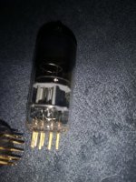
EIKI LC-XB21B /Sanyo PLC-XW57 lamp ballast did not ignite

EIKI LC-XB21B / Sanyo PLC-XW57 lamp ballast did not ignite HID lamp. Projector did not give any warning with LEDs, just 3 times try to start and then cool down lamp and goes to standby.
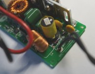
I find on ballast board 2 diodes are dead. They are in series and together parallel to output, middle point is used for ignition transformer primary (or secondary) side supply. Probably, as I not had schematic. Ballast is Rubicon RPB-7491EA, PCB is D7491M-03.
What parameters must have replacement diodes? Marking on diode is 83A, D5 on image.
Diode_DSC09383.JPG

3D printed audio stuff (with STL files)

I got into 3D printing and I think I have started already too many threads here, so I am starting this one to share my 3D printed audio stuff.

The first one is a back cover for BC 8PE21. I printed it with only 11% infill to use some leftover filament, for strength I think it would need more. Also, the strength could be improved by adding ribs - especially on the flat part, the sides seem OK. Its intended use is for using the 8PE21 with a RCF H6000 horn or with the 135 Hz midbass horn by John Inlow. It fits the driver fine. For me, making one from wood would be a nightmare. 3D printing is easy🙂

Edit: Here is the index of the posted models from page 2 on:
Post #17: Mount piece for Visaton FRS8M (by arcgotic) 3D printed audio stuff (with STL files)
Post #25: 20 cm paraline (not the best design, for experimenters only) 3D printed audio stuff (with STL files)
Post #61 Screw in driver to 3" diameter two screw bolt on (may not work for all drivers) 3D printed audio stuff (with STL files)
Post #65 8PE21 front aperture 3D printed audio stuff (with STL files)
Post #101 34c9 base 3D printed audio stuff (with STL files)

Some more K-tubes: https://www.diyaudio.com/community/threads/3d-printed-audio-stuff-with-stl-files.349459/post-6890665

Attachments

Sonore Audiobyte

SOLD!


Sonore Audiobyte, working pull from parted out TP BIII 9038 Pro DAC. I was running in synch, using clock on Audiobyte. Was using it with Roon (showed up as unidentified I2S bridge), played native DSD128, but it also connected and played from Win 11 laptop. I have a DIY manual which was copied from a post at Audio Circle. It explains the built in oversampling controlled by dip switch and how to power the USB side, if desired. I always powered it with 5v. Still a great sounding isolated USB to I2S module. $125 shipped in CONUS. Sonore has a basic description and old drivers link on their discontinued products page.

https://www.sonore.us/legacy.html

SUPPORTED PCM RATES
44.1 KHz-384 KHz

SUPPORTED DSD RATES
2.8 MHz (DSD64) - DoP, native (via ASIO)
5.6 MHz (DSD128) - DoP, native (via ASIO)
11.2 MHz (DSD256) - native (via ASIO)
22.5 MHz (DSD512) - native (via ASIO)

I'm scompracer on ebay. 100% positive feedback, 514 transactions, 133 as seller.

https://www.ebay.com/usr/scompracer#tab2

Attachments

  • 20230408_220950.jpg
    20230408_220950.jpg
    462.5 KB · Views: 120
  • 20230408_221037.jpg
    20230408_221037.jpg
    233.7 KB · Views: 105
  • 20230408_221239.jpg
    20230408_221239.jpg
    478.1 KB · Views: 110
  • 20230408_221247.jpg
    20230408_221247.jpg
    591.2 KB · Views: 120

Half wave voltage doubler circuit problem

Hi everyone!

I'm building a copy of a 1953 marathon tube amp and have ran into an issue replacing the two selenium rectifiers with 1n4007 diodes in the new build. Keeping in mind that the diodes go in reverse order from the selenium, I've wired it up to match the original.
However, the circuit isn't working, I get 119v to the first tube heater (50l6) and onwards to the last three tubes (PP 50L6 with two 12SC7s) the rectification circuit isn't generating B+ to power the rest. No voltage past the first cap (C1) I've attached a schematic of how it's currently wired. Beating my head against the wall, because it's wired as the original but no B+! What do y'all think? What am I missing?
IMG_20230408_155305145.jpg

Subwoofer BMS 12ND630

I am about to build a new set of subwoofers, based on either Faital 12PR320, or BMS 12ND630
Since, I will have a lot of room-gain, I was thinking about making it sealed, not ported.

I will have the possibility, to perform EQ, and I like the idea, of playing with REW, rather than fiffle with the ports.

My plan is to buold a 60 liter enclosure, realizing that EQ will be needed.

What are your thoughts, regarding a sealed anclosure?

Greetings from Denmark, Michael

Raid 1 for media library

Hello all
Thinking of something DIY hack against drive failure and power outage attached to the main pc. This pc has a dongle with 8 Bluetooth connection ability and a really good Wi-Fi dongle. The 65" screen attached to this is the main screen for entertainment, DAW, pc monitor

Pair of USB flash drives in raid 1 on a powered hub plugged into a solar topped powerbank? Will this work as a cheap raid 1 array accessible by all the devices on the network?

Thanks and regards
Randy

PSVane 300b MarkII T matched pair

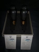
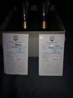
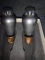
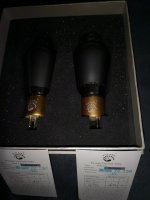
Matched pair of tubes used for about 40-50 hours in like new condition with original packing. Price is 300 euro including shipping to EU with tracking. Payment paypal for friends.

Attachments

  • IMG_20230406_160600.jpg
    IMG_20230406_160600.jpg
    296.6 KB · Views: 94
  • IMG_20230406_160604.jpg
    IMG_20230406_160604.jpg
    267.6 KB · Views: 88
  • IMG_20230406_160612.jpg
    IMG_20230406_160612.jpg
    561.4 KB · Views: 88
  • IMG_20230406_160625.jpg
    IMG_20230406_160625.jpg
    382.1 KB · Views: 79

Nikko Alpha 220 - Please help!

Hey folks,

I need some guidance here. I have some experience on class a/b amps, have troubleshooted and restored a lot of pioneers, marantz, realistic, etc...
But this is my first Nikko power amp.
I have replaced all electrolytic caps, and a few faulty components: 4 out of 8 output transistors were shorted, so I replaced all output transistors and a burnt fusible resistor.

2SA1095 -> 2SA1215 (Q733,734,737,738)
2SC2565 -> 2SC2921 (Q731,732,735,736)
2SD882 -> KSD1691 (Q727, 728)
2SB772 -> KSB1151 (Q729, 730)

There is no bias offset adjustment on this amp, just IDLE current adjustment trim pots, but the TP testing points are not showing anything usable.
Power supply seems fine, the rails are providing correct voltage but some of the output transistors are showing incorrect voltages.
On the left channel the negative side of the circuit has displaying some positive voltage on most transistors, Q733 and Q737 bases are 26v, when I presume should be showing a negative value.
On the right channel a similar problem is happening but in the positive side of the circuit...
I simply "copied" the original placements of the transistors (there are no shorts with the heatsink).
I am not leaving it on for long since it can burn something, It is drawing about 1A @ 127V.

I need a peer to review and help me to troubleshoot this issue.
DMM, o-scope, thermal camera, etc are available...

Attachments

Line source / Column Speaker

Looking to build a pair of line source/column speakers for mids-top from 250hz up. I like the width and throw of the line source design, as well as its portability. It's for a little PA with 12" Cubo kicks on each side, and a x2 12" centre cardioid sub. (it's for that sort of music with lots of head/brain Bass, rather than body bass), to be used outside in the summer and low-ceiling basements in the winter, for like 200 people.

Thinking of a column with a minimum of x8 drivers close together to minimise comb filtering using either 3" or 4" drivers.
What do people think of using a 2-way driver like a JBL stage2 4". Then I dont have to have a separate tweeter in the middle (if i did i'd go for a planar) ... unless i build a curved design, due to top end due to cancellation. If the 2-way idea is bad, I'd go for a FaitalPro 3" FE22 or Peerless TC9FD00-04

Any plans anyone? Or tips from experience? I'm fairly new to speaker building.
Hoping to find some tested plans or experience here or someone to persuade me to build something else and not buy a pair of proBox Achat 804. advice, please.

Marantz 1150D Integrated Amp Grounding Issue

Grounding issues are a pain, and trying to sort out a unit someone else has messed with is a pain. Here I have both issues in one.
Someone had messed with ground wiring at the input terminals. I think I sort of got it how it should be but am still having a weird issue. I've done a recap/overhaul on the unit but am stuck on this grounding issue.
Currently, there is a buzz in both channels.

Originally if I had a signal connected to tuner or aux it would bleed through when unselected. Distorted and at normal listening levels, unaffected by volume. The ground wire from the input switching board had been grounded to the ground of the input jacks. When I put it on the chassis this stopped happening. But there is still a buzz in the output. Unaffected by volume as well. And it is coming from the preamp as it is gone when I run a signal directly into the amp. It did seem to make some difference to the noise where I grounded this wire. If I grounded it to the ground bus at the main caps, it was louder than when grounded to the smaller bus near the terminals.

Here's the weird part that I'm hoping will give enough of a clue to figure this out.
If I ground the input signal to anywhere on the chassis, I get that distorted bleed through again. That definitely isn't normal.
I'm pretty sure this issue was here before I did my work, but someone was in here before.

Any ideas?

Attachments

  • IMG_3509.JPG
    IMG_3509.JPG
    611.8 KB · Views: 207
  • IMG_3510.JPG
    IMG_3510.JPG
    613.6 KB · Views: 156

Dayton SA1000

Greetings from Vermont
I have a Dayton SA1000 which seems to be in excellent condition. When I ran it through the pre out of my old Yamaha DSP -A3090 the volume was extremely low from a 15” sub. So I ran it through a smaller sub still minimal volume. I am not in anyway versed on repairs in regards to audio equipment. I do have a bolt meter and can follow some basic instructions. Any suggestions would be much appreciated.

What would come after an F4? Does an integrated amp make sense?

The F4 is finally back home, a few adjustments, some soldering of components which were not correctly installed, bias adjusted and voltage stable at 200mV as per project, I will soon insert it into my chain past the Audio Research SP9 while the BA-3 preamp in the build as to have an extra voltage on the output to drive the F4 but I am starting to itch at what comes next, what about a big box with both preamp and power amp, kind of a Class A integrated amp with about 50W output?

Orion HP 4800 help

Hi everyone


Trying to troubleshoot my Orion HP 4800. It powers on and works however the rear ch3/4 speaker output is very low. Gain has to be turned up almost all the way and even then it is very hushed. I assume it is some sort of fault.

When connecting the 3/4 channel to 1/2 channel speakers play nice and loud.

ESP light is constantly on.

New 15" Subwoofer Design Help

Hi,

I've built a few diy subwoofers with good results. I uploaded a pic of one I built. I want to build one more with a 15" driver for more output. I listen to mostly music and some HT. I love tight bass with no distortion. I also am into wood working so I can make any size box and have room for a nice size sub. I did want to go ported. I'm really lost on drivers and was wondering if someone could help steer me to a great 15" driver for a home subwoofer. I have a bridged amp putting out 625w at 8 ohms but may decide to go with a more powerful class D power amp. First I'll try what I have. When I called Parts Express they suggested this driver: https://www.parts-express.com/Adire-Audio-ADBR15D2RA-Brahma-15-XBL-DVC-Subwoofer-294-116?quantity=1 My budget is around 500.00 for the driver.

Any help is appreciated.

Attachments

  • 20230310_230300.jpg
    20230310_230300.jpg
    329 KB · Views: 112

Parasound A21+ right channel hissing

I bought the amp used from USAM and received it today then proceeded to set it up.

Set up consists of:

Parasound A21+
Rogue RH-5 preamp
Yamaha CD-S1000
NAD C658 DAC/pre
Mirage M760 speakers
A mix of AQ Water and Acoustic Zen Matrix Reference interconnects
Zu Audio speaker cables

As soon as I powered it up there was a very apparent and loud hiss coming from the right speaker. Left speaker is quiet.

I replaced the speaker cables and checked all connections. Hiss still present.

I used both balanced and unbalanced cconnections. Hiss still present.

I used multiple sets of balanced and unbalanced cables. Hiss still present.

I put in place a new set of speakers. Hiss is still present.

I swapped out the preamp. The hissing is still present.

I replaced the A21+ with my Pass Labs XA-25. Hissing sound is gone.

It is loud enough my wife could hear it in the next room, she has very sensitive ears. Unless you are aware of something I am not I cannot fathom where the problem lies.

I know enough to be dangerous about working on these electronic devices so I don't want to accidentlly blow something up.

Any insight from the significantly more experienced will be greatly appreciated.

Jay

SONY TA-VE800G Need help fixing

Hi,

A friend of mine bought a defective SONY TA-VE800G, since it fits the look of his other Hifi Components (Yes I know...)

The right channel is very distorted and has almost no power, at first I thought that would be an easy job, replacing a transistor or a cap.

But since the problem is not comming from the preamp nor the power amp, I am a bit clueless, maybe someone has an idea?

Also I have a quick question on the side, that "AV Reciever" doesn't have any surround input, so how the heck does it make surround sound?!


Greetings,

Plermpel

Yet another Ripole sub project

I'm building another pair of Ripole subs and sharing the build pics here. These are a bit more compact than my earlier builds.

The woofer cabs are 3/4 red oak plywood with oak edge members inserted and rounded over. This arrangement looks better than exposed plywood edges but it's a LOT more work. The "C" center section is solid brown oak indexed to the cabs with oak dowel pins. The cabs and center section are held together with all-thread rods and button head cap nuts.

The light-colored cabs will be oil stained with a mixture of 1 part golden oak, 3 parts natural, and then a bit of powdered turmeric root is added for a yellowish tint. The brown oak center section will have a darker red oak stain for a nice contrast. The finish will be two or three sprayed-on coats of clear satin polyurethane with a #320 sanding step between coats.

More to come as I complete them, but for now-- enjoy the build pics.

Below - Rabbited cab panels bank together for gluing:
fullsizeoutput_9e.jpeg


Below - Cab glued and clamped:
fullsizeoutput_a4.jpeg


Below- Cab edges notched on the table saw to accept edge inserts:
fullsizeoutput_b6.jpeg


Below- Red oak edge inserts held in place with stretched painter’s tape while the glue sets:
fullsizeoutput_bc.jpeg


Below- Cab with mitered edge inserts glued in and sanded flush:
fullsizeoutput_b8.jpeg


Below - Woodwork completed on cabs and center C-section:
Ripole Details.jpeg


Below - Rear view of assembly with edges rounded to 3/8” radius on a router table:
Ripole back.jpeg


Below - Front view, ready for stain & satin clear coat.
fullsizeoutput_c4.jpeg


Below - Details stained and first coat of satin poly clear sprayed on:
coat 1.jpg


More to come…

D3a Valvo tubes pair

Pair of tubes from Valvo Germany. I buy this about 6 months ago and used it about 100 hours in my 300b amp. They sounf verry good and there is no hiss and no hum. Price would be 40 euro plus 8,90 shipping with tracking inside EU. Payment paypal for friends.

Attachments

  • IMG_20230405_184450.jpg
    IMG_20230405_184450.jpg
    683 KB · Views: 105
  • IMG_20230405_184459.jpg
    IMG_20230405_184459.jpg
    446.8 KB · Views: 109
  • IMG_20230405_184508.jpg
    IMG_20230405_184508.jpg
    425 KB · Views: 95
  • IMG_20230405_184508.jpg
    IMG_20230405_184508.jpg
    425 KB · Views: 83
  • IMG_20230405_184513.jpg
    IMG_20230405_184513.jpg
    447.9 KB · Views: 86
  • IMG_20230405_184519.jpg
    IMG_20230405_184519.jpg
    466.4 KB · Views: 101

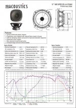
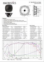
SB Acoustics COAXIAL designs with XO

Hi,

Has anyone heard/measured the SB Acoustics PFC coaxial drivers with the "factory" crossover?

SB Acoustics, SB12PFC25-4-COAX (4 inch)
SB Acoustics, SB13PFC25-4-COAX (5 inch)
SB Acoustics, SB16PFC25-4-COAX (6 inch)

I am most interested in knowing how they sound, as I am willing to use 4 or 6 of these for ATMOS and SURROUND duty.

XO are designed by SB Acoustics team and curves are optimized for 15° off-axis.

Cheers

Attachments

  • coax XO.JPG
    coax XO.JPG
    90.2 KB · Views: 1,814
  • 4inch.JPG
    4inch.JPG
    185.3 KB · Views: 1,439
  • 5inch.JPG
    5inch.JPG
    188.1 KB · Views: 1,223
  • 6inch.JPG
    6inch.JPG
    183.3 KB · Views: 1,521
  • Like
Reactions: Alexium

H-Bus connector.Hypex NCAS500MP

Hello everybody,
by no means, I'm an electronics "guru" quite the reverse.
I will appreciate if someone explains me in the simplest terms how to wire Hypex NCAS500MP H-Bus connector J7.
This amplifier has two power supplies, a standby supply and the main power supply (PS).
Would like to avoid damaging the amplifier with faulty wiring, this is why asking for very much needed help. A manual for the present amplifier is attached.
Questions I would like to ask for help to answer :
1. To activate the main power supply (PS) and power the amplifier. Is it J7.3 to J7.9 pins must be connected (wired together) ?
2. A standby supply. If I have understood correctly, can be used in external power supply 3.3VDc to 12VDc. This method is favoured by Hypex .
Is it J7.1 and J7.2 pins are used for that ?

Attachments

Sundown SFB 2000

I got a sundown sfb 2000d off of ebay. When I opened it up it had no power supply fets and 3 original output fets and 1 4115. The 4427 and gate resistors were blown also. I replaced the 4427 and the gates. Also replaced all the tl074cs. The power supply is up and running. On the output I'm not getting any switching and the clip light stays on. Nothing is getting hot. I probed the tl074cs and pin 4 I got +15.39 but on pin 11 I only get -12.05. Do I need 15 volts on both to get drive? Or is there something else I should be checking?

20230407_091106.jpg

Baxandall type 12AX7 build

I bought a PCB board for tone controls (bass and treble) Baxandall type 12AX7 from China few years ago. Finally now I got back at it again and would like to build a preamp with it.

I am thinking of using the following components:
  • Baxandall type 12AX7 PCB Board (schematic attached)
  • 2x ALPS 100k pots to use for left and right volume
  • 2x 500k double gang pots to use for bass and treble
  • 1x Sprague 8uf 1kv oil cap as I have many around awaiting to be used
  • 1x Orion PR-101 power transformer 250-0-250 @ 60mA, 6.3v @ 0.6A, 6.3v @ 1.8A, bought on ebay, removed from an old reel to reel machine
  • 1x AZ1 Mesh plate rectifier, cause they look pretty and I have few around
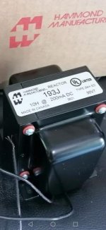
    [*]1x Raytheon 2h 0.062a 170r 450v choke
  • 1x Hammond chassis with wood frame


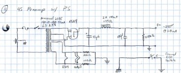
I am taking inspiration for power supply from the attached schematic of the 4S Universal Preamplifier for 12A*7 Tubes, changing the 6CA4 for AZ1, the first 33uf cap for the 8uf oil cap I have.

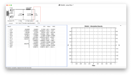
I have simulated the power supply on PSUD2. It's my first time trying to use it. I can't get the graph to populate, nor some voltages on the chart, see attached. I used 200Kohms as T1 resistance. I wasn't sure what to use so I just measured the resistance between the two 117v taps of the transformer. For C1 I used the 0.3r ESR resistance I measured on the 8uf oil cap. For C2 I speculated an ESR resistance of 0.2r. I left R1 the same, thinking is the bleeding resistor.

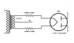
I was thinking of using the 6.3v @ 1.8a tap of the power transformer to power the 4v 1.1a filaments of the AZ1, using 1r 2w resistor on each of the filament to lower the voltage.

What's wrong with my PSUD2 model?

Thanks!

Attachments

  • H6ab52603bb414916944e0ffb2fed524b3.jpg
    H6ab52603bb414916944e0ffb2fed524b3.jpg
    64.8 KB · Views: 459
  • IMG_1961.jpeg
    IMG_1961.jpeg
    542.4 KB · Views: 314
  • IMG_1962.jpeg
    IMG_1962.jpeg
    493.1 KB · Views: 225
  • Screenshot 2023-04-06 at 10.45.14 AM.png
    Screenshot 2023-04-06 at 10.45.14 AM.png
    261.2 KB · Views: 210
  • AZ1.JPG
    AZ1.JPG
    12.3 KB · Views: 198
  • 4S-schematic copy.jpeg
    4S-schematic copy.jpeg
    83.8 KB · Views: 329

parafeed amp with Hammond 119DA transformers, what is my best circuit option?

Hello,

I have worked recently on a power hungry OTL amp and I can say now I got it straight, I enjoy the sound of it and it is well above anything solid state I've tested so far.
The problem is, it is 20kg+ and sensitive to mains Voltage swing (naturally).

A few days ago I just hooked a pair of Hammond 119DA transformers on the output and I have to say I was really surprised. I expected that it will "soften" up and "wash", it did not happen at all. In fact the base got a little tighter.

Now I'm thinking to make a less power and iron hungry amp with these transformers for my 120-300 Ohm sennheisers.

What circuit options would you suggest?

Thanks!
JG

PCB/transistor removal - thermal paste and heatsink

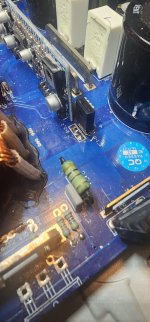
A bit of a novice here and getting more and more into DIY, I was thinking of replacing the two large filter caps in my 21 year old subwoofer plate amp. In order to do this I need to remove the board but and as you can see the PCB and transistors are screwed to the heatsink and behind the transistors is thermal paste between them and the heatsink.

How does one go about removing the board without damaging the transistors? Once off does the thermal paste then need to be removed and I would need to apply new paste?

Any help would be appreciated. Thanks!

IMG_7070.jpg

Alternative 6 Watt Amplifier with EXICON Lateral MOSFET

This is my new 6 Watt amplifier.
Now that I have ended LU1014D Small Amplifier.

This amp uses EXICON ECX10N20 Lateral MOSFET TO-247 in output.
I be back later with details and schematics.
I hope some guy is willing to draw PCB files, when the time comes.

This amplifier has THD 0.0009% 1W 8ohm in SPICE Simulation.
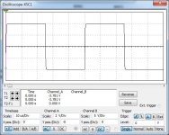
First image shows squarewave at 20kHz 4Vpeak 8ohm.
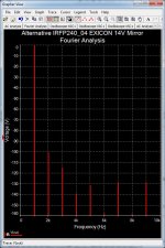
Second image shows Fourier Analysis spectrum. Mostly 2nd harmonic.

Attachments

  • Alternative EXICON 20kHz Square.jpg
    Alternative EXICON 20kHz Square.jpg
    65.9 KB · Views: 251
  • Alternative EXICON 04 Fourier Analysis .jpg
    Alternative EXICON 04 Fourier Analysis .jpg
    117.8 KB · Views: 242

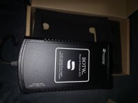
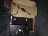
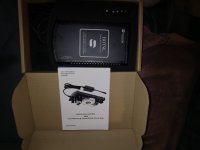
SBooster MK2 dac psu 15V

Maybe someone could use this. I dont need this anymore with this output voltage. Verry hi quality power supply. In like new condition with all documents, original packing and bill. Buyed last year from Germany. Price 250 euro including shipping inside EU. Plese look for good test and opinions on the net.

Attachments

  • IMG_20230406_174111.jpg
    IMG_20230406_174111.jpg
    392.7 KB · Views: 72
  • IMG_20230406_174119.jpg
    IMG_20230406_174119.jpg
    487.7 KB · Views: 74
  • IMG_20230406_174139.jpg
    IMG_20230406_174139.jpg
    327.5 KB · Views: 75
  • IMG_20230406_174340.jpg
    IMG_20230406_174340.jpg
    293 KB · Views: 74
  • IMG_20230406_174405.jpg
    IMG_20230406_174405.jpg
    294.9 KB · Views: 76

NAP250 amp boards & regulator boards

I'm putting together a small group buy of NAP250 boards.


This is a true nostalgia project with considerable research done into the original circuit and device selection. I'm even deleting the silkscreen and solder-mask on the boards. (It will be a two layer board with plated-through holes and a lead-free HASL finish, so not entirely old-school).

792315d1572886336-nap-140-clone-amp-kit-ebay-diynap250_schematic-jpg


790990d1572347883-nap250-clone-amp-board-front-jpg


790991d1572347883-nap250-clone-amp-board-jpg


I have designs for both the original regulators (again, without SOA), and an inverted one which references the VAS to ground, greatly increasing its PSRR at high frequency.

See more here:

NAP250 clone

Please copy the last-posted list and add your own name, along with which regulators you're interested in.

Cheers,
Jeff.

Howdy

I recently got a chance to listen to some high quality audio equipment, which made me realize my normal setup (mp3 files through my PC integrated audio and $20 headphones) is terrible so I'm looking to step up my game a bit.

I work in an electronics lab so I'm comfortable building kits, and so far I've got an Objective2 kit on the way, and the Kublik NOS DAC caught my eye. I can't pm the creator to order a kit yet since I'm a new account, but hopefully I can do so soon.

question about an old speaker design, was it good ?

Hi:
Anyone old enough to remember the Wireless World June 1979 design "Bookshelf Loudspeaker MKII" by Jim Wilkinson.
I built one back in the early 80's and still use it today. Just curious as to how good or bad it was.
It used an Audax HD13D34H tweeter and a KEF B200 ( I blew mine, so I now have B200G)
My cross over is hand wound aircore with heavy wire( some ~14 ga)
Peter

EL34 se

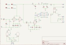
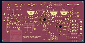
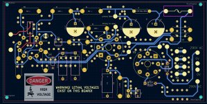
Some time ago I asked about an el34 schematic for a pair of Edcor SE transformers, I have finally got round to doing a PCB and I guess some time in the future I will eventually get round to building them. In the meanwhile here is the PCB for anyone that wants to try, files in KiCad. Any comments welcome.

Attachments

  • el34.jpg
    el34.jpg
    143.5 KB · Views: 177
  • pcb_flood.jpg
    pcb_flood.jpg
    322.3 KB · Views: 174
  • no_flood.jpg
    no_flood.jpg
    393.3 KB · Views: 166
  • el34se.zip
    el34se.zip
    235.4 KB · Views: 63

Dual 721 troubleshooting

Hello all,
I recently received a Dual 721 with badly damaged dust cover and base. Everything else looks clean and dandy but the 1.25amp fuse in the power supply was blown when I received it. I can build a hardwood base and dust cover, but I am somewhat challenged when it comes to electronics. I can solder and have a digital voltmeter And can follow instructions concerning circuit diagrams.
How should I safely approach troubleshooting the cause of the blown fuse? I have 230v at the power supply.
thanks in advance,
Peter

Pair of big heat sinks for sale - EU

Hi,

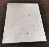
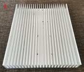
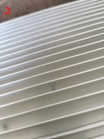
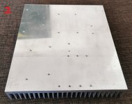
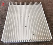
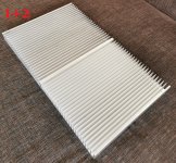
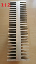
i have two used heat sinks for sale. They have some holes and scratches. The base of the heat sink is flat.

Dimensions 300x250x40mm.

One is 30€ and pair is 50€ plus shipping. EU only.

Attachments

  • IMG_20220411_113623.jpg
    IMG_20220411_113623.jpg
    265.9 KB · Views: 135
  • IMG_20220411_113638.jpg
    IMG_20220411_113638.jpg
    327.5 KB · Views: 129
  • IMG_20220411_113654.jpg
    IMG_20220411_113654.jpg
    401.2 KB · Views: 124
  • IMG_20220411_113709.jpg
    IMG_20220411_113709.jpg
    136.8 KB · Views: 127
  • IMG_20220411_113727.jpg
    IMG_20220411_113727.jpg
    281 KB · Views: 133
  • IMG_20220411_113735.jpg
    IMG_20220411_113735.jpg
    377.3 KB · Views: 135
  • IMG_20220411_113808.jpg
    IMG_20220411_113808.jpg
    647 KB · Views: 144
  • IMG_20220411_113835.jpg
    IMG_20220411_113835.jpg
    137.7 KB · Views: 137

2-Stage N-Channel Class A

Hi dearest Fellows,

Hope you rolled in the new year smoothly.

The christmas break left me with some time on my hands and after dabbling with a lot of designs of ever increasing complexity it was time to build something simple. I had been thinking of a single JFET gain stage and a class A buffer with single supply. The goal is to get a dominant second harmonic of negative phase around normal listening levels. Distortion may be audible if its the right distortion.

What I conjured up turns out to sound rather pleasing but I feel it can be optimized much further. Some pico-C here and there and it is already well behaved on breadboard and nicely quiet. Now running it at 48V and 1.35 Amps and getting about 10W into 4 ohm.

it actually is similar to the Pass' zen amps only with a separate buffer. The buffer also being Pass inspired, enjoys an active current source that creates some push pull action. A JFET driver was added in between as not to disturb the gain stage too much. The gain stage is cascoded and bootstrapped together with the driver JFET. The whole is placed within a light negative feedback loop to yield practical damping factor.
I have for you some LTspice shots. Better pictures and perhaps Arta measurements will follow.

Im leaving this here to hopefully gather your thoughts and opinions.
Much cheers and thanks to all of you.
-Ruben

Schermopname (22).png


1W 20k
THD20 1W.png

20W 20k
THD20 20W.png
20230109_234437_HDR[487].jpg

Attachments

Need help finding crossover

I have a pair of Blue Sky speakers that were originally active speakers. Due to quality control issues with the first generation PCBs, the amps were unreliable so I wired them to be bi-amped with an Ashley EQ and two AudioSource A/B amps.

Sounds ok but it's a cumbersome setup so I'm looking to convert to passive crossovers. The original specs are

Low Frequency Cutoff 80Hz
Low Frequency Rolloff 12dB per octave
System Q .707
System Crossover Frequency 1.5kHz
System Crossover Slope 4th order Linkwitz-Riley Acoustic

So, I'm looking for this:

xover for 6" driver - high pass 80hz, low pass 1.5khz

xover for tweeter - high pass 1.5khz

However, my Google fu has failed and I haven't been able to locate any crossover with those specs. I'd appreciate any suggestions, even DIY (I can solder but not design).

Thanks!

Multiple 1/4 based resonators

do YoU prefer a ‘TL’ with the driver @ 1/3 or a parallel set of ‘TL’s that connect to each other @ 3:1 ?

depending on the driver and EQ placed on the 3/4 resonance, the latter often looks pretty good? Though it’s weird how it sims after the 3/4 resonance unless i offset the driver entry to split the short side resonator. It’s like there an ‘ideal’ pattern in using these in higher order versions that becomes more and more obvious as you use it ? I used to just plave the drivers at the closed end, but moving them down to 1/3 or 1/2 REALLY helps! get a nice smooth (~flat) respomse🤓

Lately, im using the same drivers over and over in a variety of qw layouts and compare/contrast. But I often chase stupid to witness it and wood is not getting less expensive
Projects by fanatics, for fanatics
Get answers and advice for everyone wanting to learn the art of audio.
Join the Community
507,857
Members
7,891,050
Messages

Filter

Forum Statistics

Threads
406,381
Messages
7,891,050
Members
507,857
Latest member
SSIRon