sealed 2 ways with an old pair old Seas 25F-EW

A few years I build a pair of sealed 2 ways with an old pair old Seas 25f-ew 10" woofers and a Dynavox 3" Full range (in its own dagger style enclosure), using a simple 1st order crossover around the 4-500khz mark. About 30ltrs. Heavily stuffed and braced. Very happy with it.

Got another pair of the Seas woofers for super cheap. My Amp is 2.1 and I would like to use extra channel to lower the bass output.
Should a. I be using a separate box as a subwoofer? b. Use another enclosure to turn my current speaker into an improvised double chamber enclosure (raising the overall volume)? Do I even need another woofer to lower the bass output? Would just increasing the overall enclosure volume do the same job as adding another pair of drivers? Reckon I could get away with an additional box of about 40ltrs. Would porting as a reflex help at all? I'm ok with eq.
I'm imagining using a large diameter tube to create the double enclosure and the current speakers would sit on the top (also acting as a stand).

I have hornresp to model this, just looking for tips.
  • Like
Reactions: prairieboy

Tamed the AT440ML

I have owned this cartridge for two decades. It has always been a bit bright. Audio-Technica recommends 100-200pF total load for the turntable, cable, and preamp. This is a low value.

I estimate my system had ~300pF. So, I removed the 100pF loading capacitors from my DIY preamp.

The difference is apparent. The AT440ML now sounds smooth. 🙂

The Internet has a lot of posts about brightness in Audio-Technica's current models. If you own one, make sure that the capacitive loading is under 200pF. 47K resistance works well.
Ed

Attachments

  • at440ml.png
    at440ml.png
    16.6 KB · Views: 198
  • Like
Reactions: vsmusic and mlloyd1

Routing

Very quick and basic question about the miniDSP, is the following right:

If I am using a miniDSP SHD with 2 inputs and 4 outputs, I can implement a 4 way crossover with mono outputs by routing both inputs to each output channel and then applying the crossover filters independently for each output channel?

Thanks

Low Cost Optical encoder for Brushed DC Motor

Anyone can recommend a Optical encoder for Brushed DC Motor? I am working on a new Vinyl and Capstan Motor with Superior speed accuracy.
Like shown here
https://www.powerelectronicsnews.co...rushed-dc-motor-programmable-speed-regulator/
https://www.powerelectronicsnews.com/wp-content/uploads/sites/3/2022/08/10.png

One for normal sized 12v Motor and other for smaller 3V Motor.

I cannot find any reasonably priced one anywhere

Simple question to help me understand why?

Hi,

I have a power supply as shown in a valve pre-amp, and I am trying to understand what purpose the centre tap provides, and what would happen if it was no longer in place?

I also have some 800VAC caps and wondered why I could not put these across the whole voltage drop after the first centre tap capacitor pair?

Thanks for the education 🙂


Screenshot 2023-04-05 at 06.27.48.png

port location to reduce standing waves

Is there a formula or calculator to figure out the optimal placement of single or dual ports on a ported box?
Andrew Jones mentions it while unpacking his latest design
ports.jpg


The idea is to place them such so the enclosure's internal standing waves are cancelled out at the farfield. Does it mean two ports are necessary? Can someone help with this or provide tips?

Purifi with passive preamp, do I need impedance?

I am thinking of making a simple integrated amplifier, consisting of a Purifi power amplifier module.
My idea is to make a simple passive pre-amp with an input selector and a volume control, but do I need to think of input and output impedance on the pre-amp part, or is the impedance that the low ohm input selector, the volume control and the purify makes together?

Best location for an internal amp in Tham 12?

I want to put an amp and boost converter inside my Tham 12 - any suggestions on the best (or least bad) place to put it?

Should I worry about air turbulence caused by the physical intrusion of the electronics into the horn path? I'm thinking about putting it on the back panel, to one side of the brace with three holes shown in red on the right of the drawing attached. It's one of the new 3e TPA3255 amp and Wondom Boost converter.

Any better suggestions? What are the chances of this causing audible noise / impacting the sound of the speaker? Thanks!

Attachments

  • Tham 12 side view.png
    Tham 12 side view.png
    23 KB · Views: 104

Advice on output Impedance selector switch

Would really appreciated some help. I have some Welborne 300B DRD monoblocks and want to add a 8/4 ohm impedance switch/selector on the secondaries of the output transformers. (Drill a hole and fit a toggle switch to the back)

In the manual there are instructions for changing the impedance rating by connecting the different coloured secondary wires together differently, to four posts on the internal amp board

2 ohm and 16 ohm settings are also possible but I think that might get too complicated with the wiring and switch. So I just want to do 4 and 8 ohms.
Would something like a 4 pole 2 way on/on switch be suitable? and what kind of current/voltage rating?

It’s not totally straightforward to wire up, as the output and ground that go to the speaker terminals are connected to different secondary wires for 8 and 4 ohms settings.
The instructions are to solder the configs to 4 posts on the board. I’d obviously be transferring this to a switch.

Pic from the manual is here: https://ibb.co/XS5GQR1

Any help/advice on the right kind of switch and how to wire would be really appreciated. I can solder well but am not so experienced. (I do however know how be safe, such as discharging caps and check with a voltmeter before doing any work)

$2000 Max Speaker

I'm really going to do it this time, I promise! I've been running Magnepan MMGs for the past 15 years, but the buzzing is getting worse due to coil delamination. They sound amazing if you're sitting in the right spot, but I'd like something with better off axis and BASS. I don't want to run a sub currently due to preventing waking up a 1.5 yr old, so I'd like something that can run without. I think I'll put shakers in the couch.

My room is 37' L, and 33'W where the speakers are, narrows to 15' rearward of listening position (most of my house is one room), which is about 12' back. As you can see, the left speaker is in a corner, and I can't come too far out from the wall.

IMG_7105.jpg


I don't want to scratch DIY, but I want to build a known, reputable kit. I believe the main difference between a $1000 DIY speaker and a $20000 speaker is cosmetics. I've built several ugly speakers in the past, but will spend more time making a pretty one this time. I would prefer a bookshelf, but floor standing is okay as well. Any thoughts on the below kits, or any other suggestions? I'd like to spend as little as possible, but would rather spend more for a better speaker than cheap out and wonder what could have been. Oh I forgot: 90% HT, 10% music (all kinds)

Bagby Helios
Rasmusson Elsinore mk6
CSS 2TD-X
Murphy BMR
CSS 1TD-X

NAD C 325BEE Blowing 2 Fuses?

Can anyone offer any advice with this one?
I recapped this NAD amp and upon power on two fuse blew on the power board. So after examining I found two embarrassing mistakes. I had shorted the voltage regulator trace and had installed C524 the wrong polarity. So after fixing these mistakes the fuses still blow. Not the first two, they're fine, but there's an electrical hum sound then the second two fuses blow. The rest of the amp has been examined.

It's a handy amp and I'm hoping to restore this power board.

I've attached pics with red markings to show the fuses that blow and the cap I reversed.

Thanks guys!
20230502_234643.jpg

20230502_234626.jpg

20230502_234614.jpg

Musicality Perception Self-test

I just stumbled across this video of an interesting simple self-test for the interpretation/perception of musicality, for lack of a better term. It helps demonstrate the weaknesses of our human analytical auditory perception - masking, auditory memory and such. The video is 10-months old, so it may have been posted somewhere here before. YouTube link below. Enjoy.

Login to view embedded media

Selecting new 2-way front line based on crossover frequency

Hi,
sorry if this had already been discussed but i didn't manage to find exact answer.

I'm considering upgrading the front speakers of my Skoda Octavia.
As a typical VAG it has 2-way system in the front doors. A woofer in the front bottom part and a tweeter in the A-pillar.

Picture from internet:
1680445560326.png


I've looked over the specs and prices of different aftermarket manufacturers and I've found huge difference in the stated XO frequences ranging from 2.5KHz to 4-4.5KHz.
As far as I know as the frequency rises the sound tends to get directional.
For example here is a simulation of a directionality of a tweeter
1680446596446.png


And here is a simulation of a 6.5" woofer
1680446667992.png


So basically when the woofer is in the driver's footwell then the driver will hear almost nothing from it above 2KHz.

Am I going on the right track thinking that I should limit my search to a aftermarket 2-way system with XO less than 2.5KHz?

Need help with a Borbely DC100 build . . . an output stage cap value is unclear.

This project has been sitting around for decades, and I'm finally getting around to finishing the amp (hopefully!)

The original MOSFET amp build articles are in volumes 1 & 2 of the 1984 TAA. The first article dealt with his Servo amp; the second with the model DC100 - which I'm building.

They both use the same MOSFET output stage, originally spec'd for a pair each of 2SJ49 and 2SK134 per channel (8 devices total). I'm repurposing another amp that has room for only 4 MOSFETS, so I'm substituting UST20N20N & UST20P20 instead.

Borbely notes that the P channel devices have a higher gate capacitance (approx. 300 pF) than the N channel, so he shows 330 pF caps added to each gate of the 2SK134s.

There were subsequent circuit modifications / corrections (1/85 has the wrong schematic!) and then the supposedly correct schematic in the 2/85 issue. The "correct" schematic shows only 33 pF caps added to each gate. I think it's a typo, and it should be 330 as before.

His Hafler DH220 shows a 630 pF connected between the gate of the first device (of two) and the source of the 2nd device.

The XL-280 shows a 910 pF cap shared among 3 devices.

I may have answered my own question, i.e. a single 330 pF cap per N channel device is correct? (I can upload schematics if needed).

Any other suggestions from folks who have built one of these?

Thanks in advance!

Unusual find. Acoustical manufacturing company QA12 with preamplifier

PXL_20230401_144343029.jpg

I've conducted internet searches and this is a rare amplifier. 1 in a 1000 compared to 1 in 90000 for a QUAD II. I'd love to make a stereo pair. Any ideas? Don't worry, I am not going to try switching on, any advice on bringing this all original back to life. New capacitors etc. Or don't touch and keep as museum piece.

Sony CDP-337ESD with strangest problem ever times 2, just listen!

This used to be my favourite player till volumio…
However, after 12 years in storage I decided to listen to it one more time as a reality sound check.
I connected my beloved player to the system, i inserted a cd which was red in a split second, pressed 5, and…disaster hit “private investigations” was completely covered by some kind of very powerful annoying digital noise!
I checked every single electrolytic cap and power supply and regulators and everything is within spec or better! And as if this is not enough I found another guy in youtube having exactly the same weird problem! Check this sound out at 337esd video
What is even more weird, is that I tried an external dac and although it locks excellent, the outcome is exactly the same, a lot of noise!
I have no idea what else to try, thus I really could use some help here.
Any input or idea is welcomed as my experience with cd players is limited.

thank you !

Musical Fidelity X-Can V2 Tube Headphone amp power supply

Dear All, I lost the Musical Fidelity X-Can V2 Tube Headphone amp power supply and I need one. I am not looking for audiophile or fancy power supply. Just the replacement of stock one. The manual says it requires .12V AC 500mA . I have a PYRAMID PS3KX 3Amp 13.8V Power Supply which I used with Musical Fidelity V-90 Dac. Can I use the PYRAMID Power Supply with X-Can V2? I also found this power supply in my stereo system(Picture atttached). Would this work for X-Can? My electrical knowledge is very limited and I dont want to kill X-Can V2 with the wrong adapter. Any advise would be appreciated.

Thanks
Kris

Attachments

  • PXL_20230427_214738166.jpg
    PXL_20230427_214738166.jpg
    460.7 KB · Views: 159

Microphones: What is the relationship between the companies DPA and B&K?

I do not have a clear view but here's what I think the situation is:

B&K shut down their microphone division some years ago
DPA is part of, but not all of, the old B&K microphone division
DPA is the recording / musician product line, but they do not make 'measuring microphones' as such
The old B&K measuring microphone line (example: the 4133) is not made by anyone any more and never had any successors

...Do I have that right? Thanks.

  • Locked
do marketers lie to us too much?

Some of the claims seem very dodgy right from the start. Peloton claims 92% continued users success rate. I also remember many of there sales came during the height of the pandemic. When people can be prone to such purchases out of boredom, or the will was sincerely there. Like usual with gym equipment. 92 percent continued user's I don't believe an inflated claim. It would be a first in that industry.

Its not just there commercial, there are others.

Are consumer's being shoveled way too much poop?

In these capitalistic times I know there wouldn't be any other way.

DF1704 and DF1706 oversamplers (for TI /Burr-Brown DACs only; or generic?)

TI / Burr-Brown released the 96k DF1704 in early 2001, and the 192k DF1706 a few years later, as a companion DF's for their "high-rated" PCM1704 DAC.
https://www.ti.com/lit/ds/symlink/df1704.pdf
https://media.digikey.com/pdf/Data Sheets/Texas Instruments PDFs/DF1706.pdf
What's a bit odd is that the datasheets for both the 1704 and 1706 state: " COMPANION DIGITAL FILTER FOR THE PCM1704 24-BIT AUDIO DAC"
Is there anything inherent to these DFs that makes them compatible only -- or simply ideal for use -- with PCM1704s?
Or are they generic enough to be used with other DACs?

I have a few of each in my parts bin. But I no longer have the PCM1704s. It would be interesting to use the DF1704 for another DAC in my bin, say a multi-bit dac that has no OS built in.

EDIT: Just checked my parts bin. I do have some TI and other manuf DACs that will allow their internal DFs to be bypassed. E.g., PCM1794. This might be an interesting experiment for the DF1704/6.

Help with my first chip amp design using chatGPT

1682496636891.png


Parts list:
Capacitor (C) - 10 µF (microfarads), 50V - serves as both the coupling capacitor and the high-pass filter capacitor
Resistor (Rf) - 2.4 kΩ (kiloohms), 1/4W - fixed resistor for the high-pass filter
Potentiometer (P) - 10 kΩ (kiloohms), linear taper, rated for at least 24V - acts as a variable resistor for the gain control
Non-inverting input resistor (R1) - 1 kΩ (kiloohms), 1/4W
Feedback resistor (R2) - 9 kΩ (kiloohms), 1/4W
Op-amp (U1) - OPAx134 series (e.g., OPA134PA), rated for ±2.5V to ±18V dual supply or 5V to 36V single supply - a rail-to-rail operational amplifier
TPA3118 mono digital amplifier board - rated for a supply voltage range of 8V to 26V, and up to 3A of output current.

Wiring instructions:
1. Connect the bass guitar input signal to one end of the resistor Rf (2.4 kΩ). Connect the other end of Rf to one end of capacitor C (10 µF, 50V). The resistor Rf and capacitor C form the high-pass filter.
2. Connect the other end of capacitor C to the non-inverting input (+) of the op-amp (OPAx134).
3. Connect one end of resistor R1 (1 kΩ) to the junction of capacitor C and the non-inverting input (+) of the op-amp.
4. Connect the inverting input (-) of the op-amp to the junction of resistors R1 and R2 (9 kΩ). Connect the other end of R2 to the ground (GND).
5.Connect the wiper (middle pin) of the potentiometer P (10 kΩ) to the junction of the capacitor C and the non-inverting input (+) of the op-amp. Connect one end of P to the output of the op-amp and the other end to the ground (GND). The potentiometer P acts as a variable resistor for gain control.
6. Connect the other end of resistor R1 to the output of the op-amp.
7. Connect the output of the op-amp to the audio input of the TPA3110 amplifier board.
8. Connect the speaker to the output of the TPA3110 amplifier board, observing the correct polarity (positive and negative terminals) according to the board's specification.
9. Connect all GND points together: the GND of the op-amp, the GND of the TPA3110 amplifier board, and the GND of the external power plug.

I used chat GPT to design an ultra-simple bass amplifier around the TPA3110 and I was following along until step 5, but step 6 says I should connect R1 to the output of the op amp but there is already something connected there. Where did I mess up? Also, how do I "connect all ground points together" when it gets to step 9? Should I physically link the grounds, or does it mean they should all go to the chasis? Thanks for your help!

UT Source sells FAKE Pairs period

I just purchased 2sa970-BL and 2sc2240-BL toshiba low noise transistors neither one looked even clost to toshiba and both had steel leads i have bought transistors for decades and never such a blatent lie the pictures were of real toshiba parts what i got was junk barely legible and both parts measured way off the best one for 2240-bl was 236 HFE and the 970-bl was 209 some were below 200 WOW is all i can say do not buy from them unless you want to destroy what you have buy from AMPSLAB i have bought from him several times although not cheap i have always received good REAL parts from him and he can be trusted another great solution is to buy SMD 2sa1163 is exact of 2sa970 and 2sc2713 is exact same as 2sc2240 they have gr and bl for both and i can tell you what i just bough the 2sa1163 avg was 500 to 510 HFE in BL and the 2sc2713 avg was 480 HFE in BL geat match right out of the package i bought the adapters on Amazon for 50 of them its 8 dollars and i also bought a 100' coil of bare tinned copper wire 26awg solid for 9 dollars i made about 2 dozen pairs in couple hours and results were typical Toshiba very predictable performance and the hfe numbers from them are consistent price was 13 dollars per 100 transistors from mouser for BL and 9 dollars for GR SAVE YOUSELF MONEY AND FRUSTRATION DONT BUY FROM UTSOURCE THEY BURNED ME TWICE IM HOPING I SAVE JUST 1 PERSON THE TROUBLE BY SEEING THIS POST
  • Like
Reactions: Thmartin

Wiggles / ripple on impedance response

I have this speaker I designed and built almost 10 years ago, AE TD15M in 5cu.ft reflex with BMS 4550 on QSC waveguide, active with MiniDSP 2x4 and 4 channels of ICEpower 50ASX2. I've been doing some modifications and improvements, such as bracing and absorption and was taking measurements to re-evaluate the crossover.

When measuring the impedance for the tweeter, I get wiggles on the response curve. I don't recall these from back then, nor from other drivers, but it's been a long time and I used different gear and software back then. Here are a few traces I took as a bit of a sanity check. I'm using REW with a Behringer UCA222 interface and impedance jig with 96ohm resistor, full-calibration.

In case the naming conventions in my legend are a bit arcane:

Violet: 8R2 resistor
Yellow: naked BMS 4540ND, on the edge of a table
Blue: BMS 4540ND on JBL 6" PT waveguide, on the edge of a table
Green: BMS 4550 (unit A) on QSC waveguide, mounted on the enclosure
Red: BMS 4550 (unit B) on QSC waveguide, mounted on the enclosure

impedance_wiggle.png

I wasn't up to detaching a 4550 from the speaker when measuring the above, but a recent 'naked' measurement showed a fairly 'clean' trace, comparable to the naked 4540ND.

It seems that the waveguide-mounted drivers have that wiggle. I was first doubting the seal of the BMS 4550 on the QSC, as I had noticed a certain bow of the mounting flange, but sanded the brackets slightly to bring it back flat and the driver exit seems quite well-fitted to the throat, with slight compression of the gasket material. The BMS 4540ND also fits the 6" JBL waveguide like a shoe, it's like they were made for each other.

My concern was initially with similar ripple on the IR of the tweeter, but I can't do anything louder than impedance measurements at this time in the evening, so hence the impedance comparison above. Here are the IR traces still, tweeter's to begin.

tweeter_IR.png

The woofer's IR does not have these OTOH.

woofer_IR.png

So what could be going on here?
  • Like
Reactions: DualTriode

Vintage JVC

While visiting relatives in Slovakia, i tested my old hifi. If i remember correctly, this i got in early 80's. So this JVC stuff is 40 years old. Still works fine. Tuner is little drifting, signal selector on integrated amp needs deoxit, but all works. The original cassette deck is gone, was warned out, the replacement, not part of this, is great.
Right now there are two sets of small bookshelfs (tesla), as my floorstanders were given to my brother. Together with my real hifi, top of the line Technics.

One thing i noticed, this integrated JVC amp has variable loudness pot, which is usefull. And it does not have preamp section, the bass/treble is part of feedback of power amp. Interesting. I have seen this in Luxman.

If i had soldering iron, i would replace input cap, and feedback cap with mp. But i got nothing here. So it has to stay as is. No recap, no repair was done on this JVC stuff in 40 years.
In US i used to collect SuperA JVC stuff, still have some receivers, cassette deck and cd player. I was always impressed by quality and durability, yet affordable JVC stuff. May not be as fancy as Marantz or Luxman, but for me JVC and Technics was just right.

Posting just for fun.

Attachments

  • 20230426_083304.jpg
    20230426_083304.jpg
    332.2 KB · Views: 231
  • A10X_SM_JVC_0011 (1).jpg
    A10X_SM_JVC_0011 (1).jpg
    52.4 KB · Views: 222

Bad re-coning or how it was stored?...possible solutions?

A few years back i did a trade + cash with a 80 yeras old gentleman that had given up his 30+ year diy JBL project.
He had brand new un used JBL 2235h in orginal boxes from 1994 with same serialnumber on driver and boxes.
He also had JBL 2405h in orginal boxes/same serienumber and also JBL E-145 orginal boxes/same serienumber. ( and some more)

The E-145 and the 2405h was used a little 30 years ago in a project he sadly never finished, and he doesn't remember exactly if they were these E-145s that he had re-coned about 20-25 years ago and then never used again. ( it could have been another pair JBL 2226, he has had many jbl drivers in his life)

No to my problem.
I´ve come to testing/mesauring my new diy jbl speaker, and there is a a slight scraping sound from the E-145.
It looks brand new and are visualy perfect, so it make my real sad someting is wrong with the driver.

Low on cash and not many JBL experts in small Sweden, so i begain to investigate the driver.
With the driver mounted:

If i push the cone with 2 hands ( one on each side) the driver makes a scratch sound with right hand 2 a clock and left hand 8 a clock.
It begains a little at 12:30 a clock, is the worst at 2 a clock and ends at 4 a clock. ( i put tape at the points)

If i only puch the cone with left hand on the left side of the cone at 8 a clock its dead quiet.
Ive read some things about mounting the "problemarea" ( in my case 2 a clock) at 12 a clock and let gravity work.

And maby heat the spider up and let it cool down hanging.
What is my options here?, it so sadly because its like new otherwise.
Are they any chances to solve the glue at dustcup, cone and adjust coil(spider/cone a little ?

I record a video of the sound pushing the cone differant ways on my phone to show you.

Login to view embedded media
Playing bass music:

Login to view embedded media
Best regards John

Attachments

  • IMG_20230501_161037.jpg
    IMG_20230501_161037.jpg
    288.7 KB · Views: 82

Toroidals For Sale

Good Morning.

I have a couple of toroidal transformers for sale in Cape Town South Africa.

1. 60-30-0-30-60 about 250VA comes out of a powered speaker, the amp was replaced with a class D amp and switch mode PSU.
2. 15-0-15 160VA never used plan was to build a power supply.
3. 2x 30-0-30 200VA used to powered a mono 125w RMS amp. I don't have mounting kits for these.
4. 25-0-25 150VA. used for about 1 hour built a 3 way LM3886 amp.

I am looking for approximately R 4000 for all of them but is open to offers.

The person who buys them will also get thrown in
2 x Autona 125w RMS amps with massive heat sinks that is in working condition
1 x gray cabinet with the build 3 way LM3886 amp that is working
1x Gray cabinet that I planned to build the power supply in

Call me on zero eight two eight seven eight three eight three nine.

I am moving and don't have space for all the stuff anymore.

Rowe R-4359A Amplifier

Hi all.
I just picked one of these up for cheap. Anybody familiar with this amp? I looked over a few posts but no real info I could use. I haven't tried to power it up yet. I found a schematic but it doesn't show any of the socket-ed inserts ( i.e... Volume, Mute, Phono Speakers, and external speakers).
I'm assuming I wouldn't be so lucky as to not need to use any of these to complete the circuit. Ultimately, I'd like to use it "as is" as a stereo power amp. I'm not trying to convert it into a guitar amp or anything. Here's some pics. Let me know what you think!

Thanks in advance! :xfingers:

Attachments

  • R-4359low.jpg
    R-4359low.jpg
    525.7 KB · Views: 1,611
  • IMG_0183_zpsl9jqexba.jpg
    IMG_0183_zpsl9jqexba.jpg
    240.8 KB · Views: 1,535

For Sale 1952 Rek-O-Kut B-16H in Rarer C7B cabinet, restored, will deliver within 1000 miles from Minnesota

Price reduction to $3000

I have posted a thread of this restoration project here and she's finished and for sale $3100 plus $400 for delivery.


PLEASE READ THE DESCRIPTION, I WILL NOT SHIP, but I will drop off at the shipper of your choice or I WILL deliver up to 1000 MILES MAXIMUM FROM MINNEAPOLIS (For a Fee) AND MAKE THE TRANSFER OR YOU CAN COME AND GET IT. If you have a shipper who will crate it, send them over. It is also available without the cabinet which may make it easier and cheaper.


Countless hours have been put into the process of rebuilding/restoring and it shows. Everything has been done

REK O KUT B-16H with a Pickering 190D tonearm and a Pickering NOS V-15 Cart. Also has the original C-7B cabinet which most people threw out 30 years ago and this is the only one I have seen except in the 1955 Allied catalog. When I refinished the cabinet, this gorgeous Red Gum veneer was underneath the gray industrial paint and I didn't want to hide it. This unit was in need of restoration. I have a ton more pics and if you are interested, I can tell you what has been done if you message me.

I It has had a new Cardas tonearm wiring kit installed and tested to check for hum. This thing sounds very nice and should last another 70 years. I put in a new motor cap since the original was leaking, rebuilt Idler Wheels by Voice Of Music, 3 speeds (45/33/78) and will play 12" 33 1/3, or 16" 78's and is easy to return it to mono if you want but it sounds great. The Pickering 190D arm may look clunky but they have a big following. It's easy to set up too. It's got a new ATE stylus on it. Speed is spot on. The motor was completely disassembled and cleaned, inspected, lubed and remounted with the OEM motor mounts. I broke it in with about 10 straight hours hooked up to my Phase Linear and the new owner is going to have a showcase piece. Thanks for checking it out. You don't see many of these and this is the only one I have seen with this cabinet which has 2 drawers and would be great to put a nice receiver in the top drawer and some of your favorite albums in and I will be including a very quiet fan system to evac any heat as the back has screen to help it breath.

IMG_6769.JPG
IMG_6768.JPG
IMG_6771.JPG
IMG_6770.JPG
IMG_6777.JPG
  • Like
Reactions: Hifihunter

Looking for info on 6.3V AC indicator in DIY tube amp: type of lamp to fit in ?

Hi

I rebuilt a "CIBOT" / "MERLEAU" DIY tube amp about 2years ago. The amp is now playing music, yet, one thing that doesn't work is the "power indicator" / "power light"
From the schematic of the amp and the measurements, this is 6.3 volts AC.
Yet, i can not figure out which type of lamp i should put inside the indicator (orange part) or if the orange plastic was supposed to light up (doubtful as it is plastic looking and from the 70's)
The orange part (with metallic butt) is screwed in the panel thread.
I don't know if i am supposed to put something / a lamp inside the orange part or replace it by a lamp.
Thread seem to be roughly 5mm
(I can find infos on similar devices from guitar tube amp, but the dimensions are much bigger each time, at least from what i could find on the internet)

Does it ring a bell to somebody ? A name / spec for those kinds of panel indicator which would lead me to the remplacement part ?

Thank in advance and have a nice day.

Attachments

  • Ampli Cibot 2x10 Watts JPEG Extract 2.jpg
    Ampli Cibot 2x10 Watts JPEG Extract 2.jpg
    350 KB · Views: 94
  • tempImageWfYFPt.gif
    tempImageWfYFPt.gif
    1.6 MB · Views: 93
  • tempImageGEXEYn.gif
    tempImageGEXEYn.gif
    405.8 KB · Views: 78
  • tempImage5DWdCR.gif
    tempImage5DWdCR.gif
    421.3 KB · Views: 84
  • tempImage1FkzGz.gif
    tempImage1FkzGz.gif
    1.5 MB · Views: 87
  • tempImageIXPsfu.gif
    tempImageIXPsfu.gif
    1.5 MB · Views: 84
  • tempImageJnXpUg.gif
    tempImageJnXpUg.gif
    1.5 MB · Views: 88

Komuro 300B Build

I'm planning to breadboard the old Komuro 300B circuit once I've completed my current project. There are two questions that occur to me after studying the schematic.

1. What is the purpose of the connection from the voltage divider off the 6V6 cathode network to one leg of the 6.3V heater winding (dark grey circles in the attached schematic)? Is it to raise the heater voltage and maybe provide some hum suppression?

2. For the 120V power transformer (light grey circle), if my mains voltage is 120V, can I just connect the rectifier diode bridge to the power switch? Seems like it would be a good way to reduce parts cost and space usage.

Thanks!

Jeff

Attachments

  • komuro_300B.jpg
    komuro_300B.jpg
    170.6 KB · Views: 833

Wanted: Original Genuine Green Toshiba 2sj201-Y + 2sk1530-Y mosfet pair from early or mid 1990s

Dear Members, I am looking to buy a pair of obsolete Toshiba Mosfets. yes, I am fully aware that they are rare, and not produced in past 30 years, but I'm certain that some members have unused pair(s) sitting in a desk draw or parts bin. NO, I'm not looking for newer release or newer types. I am looking to buy Original Genuine Green color Toshiba 2sj201 Rank-Y + 2sk1530 Rank-Y pair. I am looking for early 1990s or mid 1990s ones. because i'm trying to match it to an existing 1992 pair i have. Please see attached pictures for your review. If you have a pair, please PM me. Thank you for your attention and thank you for reading.

Attachments

  • 05 2sj201-Y.jpg
    05 2sj201-Y.jpg
    208.9 KB · Views: 280
  • 02 2sj201-Y.jpg
    02 2sj201-Y.jpg
    263.2 KB · Views: 230

Universal balanced receiver preamp based on THAT1200 1203 1206 open source PCB

While designing LM3886-based amplifier I desired to have balanced inputs. Few options were considered, but I ended up going with balanced input line receiver based on THAT chips. Below are attached schematics and gerber files for those interested.

PCB has a dedicated space for the XLR / TRS combo connector by Neutric - Mouser part # 568-NCJ9FI-H.
Another cool feature of the board is that both chips are bypassed by both ceramic and by aluminum organic polymer capacitors.

There is no power regulators included on the board - it will need regulated dual +/- 15V power.

Parts list:
  • C1 - C4 are 470pF - space is provisioned for poly caps - something like WIMA FKP2 - Mouser part number 505-FKP2C04701D0MC0
  • C5, C6 are 100pF - TDK C0G - 810-FG18C0G1H101JNT6
  • C7, C8 - 220uF - Panasonic Aluminum Organic Polymer Capacitors - 667-16SEPC220MD+S
  • C9 - C12 - 0.1uF - TDK X7R - 810-FG18X7R1H104KNT6
  • C13 - C16 - Panasonic Aluminum Organic Polymer Capacitors - 667-25SEP10M+TSS

Attachments

  • sch.PNG
    sch.PNG
    34.3 KB · Views: 404
  • 3d.PNG
    3d.PNG
    69.1 KB · Views: 384
  • pcb-t.PNG
    pcb-t.PNG
    87.3 KB · Views: 252
  • pcb-t2.PNG
    pcb-t2.PNG
    53.4 KB · Views: 204
  • pcb-b.PNG
    pcb-b.PNG
    78.8 KB · Views: 249
  • pcb-b2.PNG
    pcb-b2.PNG
    47.5 KB · Views: 338
  • Gerber_PCB_THAT1203-preamp-r1.0.zip
    Gerber_PCB_THAT1203-preamp-r1.0.zip
    80.4 KB · Views: 107

For Sale Toshiba J74 & K170 FETs BL Grade

New (NOS) genuine Toshiba J74 & K170 FETs. There are 4 of the 74s and 6 of the 170s. Will sell only as a set and won't separate. I was an authorized Parasound service center and these were purchased from Parasound parts department and Tony had matched them for me. Best reasonable offer by pm. Sold "as-is" and sale final with no returns/refunds. Plus actual shipping cost and PayPal ok with added transaction fee. USA sale only.

The 2 out-of-focus blurry ones in picture 2 are '9F'.

* SOLD *

Attachments

  • IMG_4593.JPG
    IMG_4593.JPG
    186.4 KB · Views: 110
  • IMG_4595.JPG
    IMG_4595.JPG
    193.4 KB · Views: 107

Is a hot garage bad for speakers and stereo equipment?

The title says it all, folks.

Is a hot garage bad for speakers & stereo equipment (besides shortening the life of electrolytic caps). I know temperatures below freezing can be very bad if you’re using it but I searched for heat damage on the google without success.

One of the hidden blessings I’ve found during the terrible, horrible, no good, very bad times we live in is that some projects that have been on my to do list for a loooong time are getting done now. Next up for me is a 3-4 way open baffle that I’m going to put in the garage (digital active).

I’ve had most of the drivers just taking up shelf space for several years. I am ecstatic about actually doing this project but I’m also concerned about the hot garage - also one of the drivers are EV SP12B’s that are in really good shape. Not sure if they would be more sensitive to heat than newer drivers.

I appreciate any wisdom you can send my way.

Thanks,
goody75

2-Stage Unity-Coupled Amp Concept

I've had some pretty fantastic results in 2-stage SE amp experiments with a high gain input/driver stage and output plate to driver cathode feedback. This thread tells the story of those experiments.

The key elements are:

1. High gain input stage that can swing enough volts to drive the output stage.
2. Series voltage feedback taken from output tube to input stage cathode.
3. Buffered low impedance drive of the input stage cathode to prevent input stage current feedback.

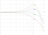
With a CCS-loaded pentode input stage, I am able to enough excess gain to get substantial feedback (30+dB) and it is easy to stabilize. Distortion is extremely low. I haven't quite got below .01% @1W but I have been very close.

The main drawback is that the output transformer is outside the loop, so all of the resistive losses and distortion added by the output transformer can't be accounted for by the feedback. Now, the distortion added by the OT turns out to be very small (since it is driven from such a low source resistance), but the resistive losses of the output transformer end up dominating the amplifer Zout. This isn't a big problem (my SE amp still has DF>10), but it got me thinking about pairing this approach with an output transformer with very low winding resistances.

You know what output transformer has very low winding resistances? My Plitron Unity-Coupled output transformers. They have an 80 Ohm primary and a .18 Ohm secondary. Driven by a very low impedance source, these transformers could achieve a DF>20, even with losses. Applying this approach to a Unity-Coupled amp could make a simple amplifier with the performance of a much more complex circuit.

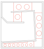
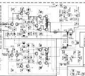
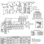
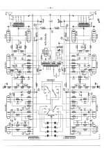
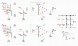
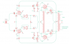
So I drew up a concept schematic of how I'd make a Unity-Coupled amp with this approach which I have attached below.

I included an input transformer because I like them. For the input tube, I chose the 12GN7. It is a high performance pentode that can stand 400V idle on the plate. I need to swing lots of volts to drive the 50% feedback output stage, so the plate will idle at the rated value. 12GN7 is CCS-loaded for maximum gain and the CCS is fed from the opposite output tube plate. Normally, with a resistive load, that would be a significant amount of positive feedback to the driver. However, with the CCS there driver gain is pretty much unaffected by the bootstrap connection. In any case, the alternative would be to construct an 800V+ supply and connect to that. This is much simpler and easier.

The feedback can be taken from the cathode winding rather than from the output tube plate. That gets rid of the huge DC offset at idle, which is really nice. I put an LM4562 follower to drive the cathode in order to make it so that I can ground the grid resistors for the 12GN7. I could have used a p-channel FET but then I'd have to put some positive bias on the grids since there is so much voltage offset in the FET.

The output stage is pretty much as my Unity-Coupled amp exists today. It is the same floating screen voltage reducer and mosfet driver for the output tubes. Mosfet drivers aren't strictly necessary as this is an AB1 amp. However, they already exist in the current iteration of the amplifier so I would leave them there if I were to get in there and change things eventually. If I were building the amp from scratch, I'd be tempted to just drive the KT88 grid resistor from the source of the mosfet in the CCS and keep things really simple.

I'd bias all tube stages with some sort of control circuit. I'd adjust the operating point of the input tubes by varying the screen voltage. The output stage bias is going to affect the operating points of the input tubes, making correct bias a bit of a headache. I'm currently dabbling in microprocessor bias control at the moment so this seems doable.

Anyway, I'd love to read some comments/thoughts from those on the forum.

I'll probably build this someday.

Attachments

  • UC_V2.PNG
    UC_V2.PNG
    45.7 KB · Views: 361

Help with I.D.

I was digging through the pile and came across these as potential donor heat sinks but then saw HCA and started having fantasies about old Parasound amps. I thought they might be Rauland but no. I looked up the silicon and if I interpret correctly these are indeed high current modules, albeit '83 TO-3 stuff. I'm a big ol' electron dummy and not afraid of asking for help. These appear to be slide-in modules for a large chassis. Just curious before I strip them out.

Attachments

  • 000_0254.JPG
    000_0254.JPG
    339 KB · Views: 105
  • 000_0255.JPG
    000_0255.JPG
    356.5 KB · Views: 113
  • 000_0257.JPG
    000_0257.JPG
    358 KB · Views: 104
  • 000_0258.JPG
    000_0258.JPG
    357.1 KB · Views: 125

Zaph ZDT 3.5 CNC cut MDF baffles for sale

I have just finished my ZDT 3.5 project (http://www.zaphaudio.com/ZDT3.5.html), and the extra set of CNC cut baffles I had made are now redundant. I paid $50 for these to be made, so that's what I'm asking for them, plus whatever good packing and shipping cost. (If you are local to Portland, Oregon local pickup is fine too.)

Fit and finish on these is very good. The tweeter especially is properly rebated to be just flush on the front and fits just snugly enough that you could consider skipping screwing them in the rear. There is no slop on any of the driver rebates - a few passes by hand with a bit of sandpaper will open up any wiggle room you'll need.

Just to be absolutely clear, I'm showing the finished speakers so you can see what a finished product can look like. What's for sale is only the set of unfinished baffles, left, right, and center, made of 3/4" MDF.

I won't be surprised if there is no immediate demand for these, so if you find this ad months in the future, don't be discouraged - I'll be storing these properly in the hopes that someone can benefit from these in the future. Get in touch if these interest you, I'd love to save someone else some time.

Attachments

  • 20230501_154854.jpg
    20230501_154854.jpg
    292.7 KB · Views: 118
  • 20230501_154548.jpg
    20230501_154548.jpg
    398.5 KB · Views: 113
  • 20230501_154629.jpg
    20230501_154629.jpg
    241.5 KB · Views: 118

Hafler P230 (cousin of the DH220)

I have a Hafler P230 I'd like to sell. It is similar to the 220 (same pc19(?) driver cards) but being the "pro" model they have 3 pairs of TO3 mosfets per channel. This amp is not factory and was rebuilt by me probably 10 years ago. The 1/4in inputs were replaced with RCA's. I replaced the small electrolytics, possibly the input pairs and other parts. It was always a great amp and served me well in home use.

I haven't used it in a long time, so I can open it up and take detailed photos and test it if there is interest. Not looking for top dollar as I am just trying to clear out old gear I don't use.

Maybe $150 plus shipping from USA 06340?

Attachments

  • 20230130_194017.jpg
    20230130_194017.jpg
    218.2 KB · Views: 233
  • 20230130_194031.jpg
    20230130_194031.jpg
    250.2 KB · Views: 243

Questions on Capacitors and Resistors

Hi All, I have some noob questions and would greatly appreciate any help/answers to my questions.

1. I purchased a bunch of resistors (carbon comp.) and capacitors about 15 years ago but have not used them as yet to upgrade my Heathkit AA-121 tube power amplifier. I am now planning to do the upgrade and was wondering if it would be okay for me to use those NOS parts (which have been sitting in my basement for the past 15 years) and save money in the bargain, or whether it would be wiser to just dump those and purchase a whole new set (of metal film resistors, to replace the c/c ones)? The amp was completely taken apart in order to repaint the chassis.

2. In the first picture, what is the blue-circled component? Is it a wirewound resistor? The rating on the component is 22K +/-1%, but the manual parts list states that those should be 22K ohm 1 Watt Matched resistors (red-red-orange). Perhaps the previous owner changed those parts? Is there any significance of getting matched resistors?
And what about the red-circled component? Is that just a tubular capacitor, .047 mfd @ 600 volts?

3. With regards to the second picture, are the red-circled and blue-circled components also wirewound resistors?

If all of these are indeed wirewound resistors, where could I purchase them from, and what should I be searching for?

Thanks.

CR

Attachments

  • 20230414_144134.jpg
    20230414_144134.jpg
    421.1 KB · Views: 104
  • 20230414_144305.jpg
    20230414_144305.jpg
    378.6 KB · Views: 109

Fountek NEO CD-1 ribbon tweeter

I have a pair of Fountek NEO CD-1 ribbon tweeters. I can't find any crossover design which uses them, and not being skilled in crossover design I don't know what to do with them. All I know is that they are supposed to cross over at 3.5K or above and preferably 18db Xover.

Would this drop into a design for a 19mm tweeter, for instance? They are 5 ohm and 90bd sensitive, so surely usable. Hopefully in a 2-way crossed over to something like a 135mm or 150mm mid-bass.

Any suggestions?

Fountek NEO CD-1.pngFountek NEO CD-1 data.png

[design log] Neat 2x170W I2S in, I2C controlled, integrated DSP amp (TAS3251)

The purpose is to design the "amplification brick" of digital centered audio systems, like systems based on Raspberry Pi, or PC music servers relying on digitalized music files. Some versatile and cheap micro-controllers (uC) have also rich audio features very suitable for audio projects like multi I2S or SPDIF outputs and DSP functions.


The sound quality shall be High. No a "No compromize" quality, but sort of 95% of that quality for a fraction of the price (adjusted pareto rule 🙂


Target applications are classic stereo systems, but more specifically multi channel active speakers, for which there are less easy to implement options for the hobbyist.


A key idea is modularity. The amplification module shall easily interface with generic, open (manufacturer independant) and well spread protocols. This ensures the possibility to be used in various projects, and on the long term:

  • I2S for the audio streams (reference interface since the beginning)
  • I2C for the control of the device (propocol that we can find in any uC


The DSP in feature opens possibilities of removing analog filters, easy performance of tests and experiments on filters, easy implementation of active speakers with oly one digital in wire....

As much as possible the design of the "brick" shall not enforce usage options. I should, as far as possible, let the end user choose how he wants to use the amplification chip. This is a key difference with the ready made amps, where the cheap price comes with an heavy lack of flexibility. Some flexibility for the tuning of some key components would be an advantage (like output selfs and caps).


The final system should be cost competive with the latest Hypex fusion plates DIYclassd.com. 300€ for 2x125W + DSP + Power supply. Is it achievable to have a similar thing for 100€ ?


Last, It would be possible to build from PCB by the hobbyist, with achievable SMD soldering. This is to ensure that even if no manufacturing, the design could be useful to hobbyists.

Sugden CD Player (TDA1541, SAA7220) NOS and Clock

The Sugden SDT-1 player is a normal TDA1541/SAA7220 arrangement, but I don't see a SAA7310 chip; either I've missed it or something else does the same functions.
I have reworked it with very many good quality new caps (oscons near the dac chip) and changed to NOS by simple wiring as usual. Results are good.

I now intend to upgrade the clock and, even after lots of reading, I'm still confused about clock distribution, different frequencies etc.
But the mists may be clearing after reading good info here, and study of the SAA7220 datasheet.

I see that the TDA takes clocks lower than the 11.289 MHz, but in NOS connection the right frequencies must be coming from the 7310 or similar source.
The 7310 takes its clock from SAA7220 output on its pin 9, and the 7220 datasheets shows this as 11.2896MHz. So I guess the 7310 (or whatever I have) itself derives the lower clock frequencies and, in NOS mode, these are passed direct to the TDA; so all clocks are in synch.

It seems to me that if I remove the SAA7220 and simply connect a new clock in place of the 7220 clock output on pin 9, it should work.

The SAA7220 plugs in, so I can try the following. Remove the 7220. Mount the clock board on a piece of plastic and glue this to the top of a DIL plug, wire the clock + to pin 9 and the clock - to pin 12 (earth). Seems to me this will work and will give benefits of a better clock, though perhaps not quite as good as the complex schemes I've seen of frequency dividers and rewiring of all the clocks.

Am I on the right path? Looks worth trying, as I've seen this player criticised for having a poor clock.

By the way, it is lampizated with excellent results! 6SL7 / E80CC mu follower at about 2.5mA, 165V across the 6SL7, 115V on the E80CC, 24kohm anode load.

Soundstream VGA1600.2

Anyone got pics or a schematic for or similar to this amp?
I got this one in, cust had it at another tech; one shorted output and 15v regulator with burnt power supply, there seems to be some parts missing around the sg3525 and a resistor mod to pin 10 from the TL072, R81, R82, R83 (burnt) all read open.

Thus far I’ve removed the shorted output, and replaced the tip42 regulator. I’ve soldered in one PS Fet per bank and jumpered the sg3525 to start pulsing. The amplifier powers up ok and passes clean audio on both channels.
I believe the missing and burnt components are part of the regulation circuit for this amp. The rails measure +/-70vdc at 11.2vdc input, if I increase the input voltage it goes up. The rail caps are 100v.

Attachments

  • 7A6D7D29-DD68-4402-86C6-12057B386452.jpeg
    7A6D7D29-DD68-4402-86C6-12057B386452.jpeg
    335.7 KB · Views: 91
  • 4D81646A-A961-4797-9F4C-840233F13575.jpeg
    4D81646A-A961-4797-9F4C-840233F13575.jpeg
    514.4 KB · Views: 84
  • 8546793B-7EE4-4784-9BC3-4FA911B89816.jpeg
    8546793B-7EE4-4784-9BC3-4FA911B89816.jpeg
    387.2 KB · Views: 82
  • 68FA3F68-7BCD-49C7-B37A-9E4A5490665E.jpeg
    68FA3F68-7BCD-49C7-B37A-9E4A5490665E.jpeg
    538.9 KB · Views: 94

Tubelab SPP with EL86/6CW5

I have just finished my 2nd SPP, this one using the EL86 variant.

After one teething problem - due to the difficulty reading the colours on those tiny 1/4 watt resistors (I am going to start to use 0.6 watt to make it easier) - I had a living, breathing amp, producing sweet music. The sound was comparable to my 6P14P (Russian EL84) one.

However after 20 minutes or so I noticed the tubes were starting to take on a orange-ish hue, the dreaded red plate.

Checking voltages, I see (with some variation between the tubes)
V(k) - 17v
V(a) - 210v
V(g1) - 0.02v
V(g2) - 211v

Voltage across the screen resistor (100 ohms) is 0.3v, so I(g2) = 3ma
Voltage across the cathode bias resistor (270 ohms) is 17v, so I(k) = 63ma

Plate voltage is (210 - 17) = 193v. Therefore dissipation is 193 * (63 - 3), which is 11.6W.

Assuming my maths is OK, and my rookie knowledge is not too lacking, then I suppose that dissipation figure is not so high, but I have read that cathode current should be restricted to 50ma.

Should I contemplate a 390 ohm bias resistor?

Out of interest - why is the bias resistor 5W? Is there a spike in voltage or current at some point?

And also, what is the benefit of having seperate resistors? Lots of PP designs using a common resistor, and a lot of the tube data assumes a single resistor in a PP setup.


I have two pairs of tubes, one is Philips NOS and the other is HQ, which looks like an old brand but I had not heard of before I bought them.

The HQ tubes are not as well balanced as the Philips ones (19.6 and 15.6 V(k)), and I suppose that is down to them not being a quality brand.

Does anyone ever fit a balancing trimmer from each of the bias resistors with the wiper going to ground?

Orion 2100HCCA PS1 problem

This is a new problem for me on these. The amp came in with fuse blown of the PS nearest the power terminals and speaker plug. Without that fuse, the amp powers and will likely play on the surviving PS2. With a new fuse in PS1 the amp draws excessively and those PS fets get warm fairly quick.

I removed the board from the sync. PS1 fets are all testing OK but Im not really sure what's going on. Drive signal to the FETs is about 1/4 the strength of PS2. I removed the MPSA06/56 drivers from PS1 and the amp powers up on PS2 but without PS1 operating. It would seem that Im not seeing enough voltage on the NPN collectors of the PS1 drivers, but not sure. I removed the 2n6488 which feeds the NPN collectors and that part is testing ok. Its hard to tell what and why there is a problem here and Im scratching my head a bit.

Usually I find these amps with completely blown PSs but not this one. Its possible the PS Fets really have failed but I dont want to risk removing them all.

Rectifiers are testing OK in circuit. The transformer could be shorted but Im not really sure. I measure a few hundred ohms from primary to secondary just like PS2.

Thoughts?

AudioFlix AF50

I've been working on this since months now, i would like to show you guys my progress.
It's a class AB amp based on the JAT501 design, classic design Push Pull emitter followers, biased at ~60mA, sounds really nice.
One issue so far, the Class A voltage amplifier Q13 gets really hot and sometimes it fails, i wonder if i could swap it with a better one...
I do accept improvements and critiques:

cW8Zsmh.png

gpm0jLm.png

nzri6Wm.png

FS (Europe) Twisted Pear modules

Hi all,

I've got some Twisted Pear modules for sale.
All items have been tested Ok, fully functional condition.

OTTO switch (20€) OTTO-II 2:1 Switching Module

USB Receiver (30€) The USB DAC/Receiver

WM8804 SPDIF (50€) The S/PDIF Transceiver Module

+ Paypal & shipping

More TP stuff for sale soonly : Opus DAC WM8740 / Bipolar Power Supply (LCBPS)

PM for details 😉

Attachments

  • OTTO a.jpg
    OTTO a.jpg
    89.5 KB · Views: 229
  • USB Receivera.jpg
    USB Receivera.jpg
    94.1 KB · Views: 224
  • WM8804b.jpg
    WM8804b.jpg
    135.8 KB · Views: 217

Free Parts Essay Contest

I am cleaning out a bit. I am putting a lot of parts in a USPS 12" x 12" x 6" box. It will ship free to whoever can do the best 300 words or less essay on why they should get the box entirely for free. You can also mention what parts you would like, including, semiconductors, transformers, heatsinks, connectors, resistors, capacitors, hardware etc. (You might mention your line voltage!)

The contest will be open at least until September 1, 2020.

P.M.s will disqualify anyone sending one!

Hammond large isolation/power transformer

For sale is a 10 lb Hammond isolation transformer Model PH350SP. I used this on the bench as a power transformer for testing tube amp circuits. I used Cree Schottky diodes to make a center tap. I bought new and used very minimally. Has lots of options for connecting. Comes with original box and terminal covers. $55 shipped inside US OBO.

https://www.galco.com/ph350sp-hammond-power-solutions.html

Attachments

  • IMG_7697.jpg
    IMG_7697.jpg
    329.2 KB · Views: 91
  • IMG_7698.jpg
    IMG_7698.jpg
    353 KB · Views: 91
  • IMG_7702.jpg
    IMG_7702.jpg
    400.8 KB · Views: 84
  • IMG_7703.jpg
    IMG_7703.jpg
    374.9 KB · Views: 94

How does Troels' measurement here show no baffle step loss?

On Troels' Discovery 3WC-10, I'm unclear how the bass driver measurement shown can be real as it doesn't show any baffle step loss or expected diffraction?

10" 26W 4534 datasheet - nominal sensitivity 90.5db, SD 350cm^2

Troels' 26W measurement on baffle 320mm wide x 495mm high with no crossover. 100hz = approx 91db
26w measurement.png


I may not have done this right but I traced the SPL from the datasheet and used the diffraction and calculator tool for the baffle in vc and I get this. 100hz more like 86db.
26w vcad baffle.jpg


He says his measurement is merged with nearfield response at 200hz, but can someone explain what's what?

The same issue arises with presentation of the 6" midrange measurements, too.

Wouldn't the system SPL tuning be completely off doing this? He claims system spl of 89-90db.

Attachments

  • Like
Reactions: ianbo

Where to find (back) panel mounted voltmeter?

Looking for a back mounted analog voltmeter for a tube build I’m working on.

I’d like it to display bias voltage which is 40mA or 40mV when measured across the 1R cathode bias sensing resistors.

I could make the voltage 400mV with a 10R cathode bias sensing resistors.

Where can I buy an analog back panel mounted voltmeter, either 0-100mV or 0-500mV?

Odd sub box design

Ok so i was given this sub box my brother had and i'm not sure what kind of box this is. Its like a Janis or a bandpass but reversed. The face of the sub is sealed and the rear has a port. It says Hot Box on one side and has a 8" Rockford Fosgate P1 Punch sub. Anyone ever seen something like this?

Attachments

  • 70736825_680162552497099_2264245310354096128_n.jpg
    70736825_680162552497099_2264245310354096128_n.jpg
    802.3 KB · Views: 417
  • 70904259_362308761323857_917490016123355136_n.jpg
    70904259_362308761323857_917490016123355136_n.jpg
    1,004.8 KB · Views: 401
  • 70958503_490995811745266_2750944549000970240_n.jpg
    70958503_490995811745266_2750944549000970240_n.jpg
    1,009.3 KB · Views: 376
Projects by fanatics, for fanatics
Get answers and advice for everyone wanting to learn the art of audio.
Join the Community
507,807
Members
7,889,140
Messages

Filter

Forum Statistics

Threads
406,279
Messages
7,889,140
Members
507,807
Latest member
Mark1979!