I've had some pretty fantastic results in 2-stage SE amp experiments with a high gain input/driver stage and output plate to driver cathode feedback. This thread tells the story of those experiments.
The key elements are:
1. High gain input stage that can swing enough volts to drive the output stage.
2. Series voltage feedback taken from output tube to input stage cathode.
3. Buffered low impedance drive of the input stage cathode to prevent input stage current feedback.
With a CCS-loaded pentode input stage, I am able to enough excess gain to get substantial feedback (30+dB) and it is easy to stabilize. Distortion is extremely low. I haven't quite got below .01% @1W but I have been very close.
The main drawback is that the output transformer is outside the loop, so all of the resistive losses and distortion added by the output transformer can't be accounted for by the feedback. Now, the distortion added by the OT turns out to be very small (since it is driven from such a low source resistance), but the resistive losses of the output transformer end up dominating the amplifer Zout. This isn't a big problem (my SE amp still has DF>10), but it got me thinking about pairing this approach with an output transformer with very low winding resistances.
You know what output transformer has very low winding resistances? My Plitron Unity-Coupled output transformers. They have an 80 Ohm primary and a .18 Ohm secondary. Driven by a very low impedance source, these transformers could achieve a DF>20, even with losses. Applying this approach to a Unity-Coupled amp could make a simple amplifier with the performance of a much more complex circuit.
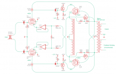
So I drew up a concept schematic of how I'd make a Unity-Coupled amp with this approach which I have attached below.
I included an input transformer because I like them. For the input tube, I chose the 12GN7. It is a high performance pentode that can stand 400V idle on the plate. I need to swing lots of volts to drive the 50% feedback output stage, so the plate will idle at the rated value. 12GN7 is CCS-loaded for maximum gain and the CCS is fed from the opposite output tube plate. Normally, with a resistive load, that would be a significant amount of positive feedback to the driver. However, with the CCS there driver gain is pretty much unaffected by the bootstrap connection. In any case, the alternative would be to construct an 800V+ supply and connect to that. This is much simpler and easier.
The feedback can be taken from the cathode winding rather than from the output tube plate. That gets rid of the huge DC offset at idle, which is really nice. I put an LM4562 follower to drive the cathode in order to make it so that I can ground the grid resistors for the 12GN7. I could have used a p-channel FET but then I'd have to put some positive bias on the grids since there is so much voltage offset in the FET.
The output stage is pretty much as my Unity-Coupled amp exists today. It is the same floating screen voltage reducer and mosfet driver for the output tubes. Mosfet drivers aren't strictly necessary as this is an AB1 amp. However, they already exist in the current iteration of the amplifier so I would leave them there if I were to get in there and change things eventually. If I were building the amp from scratch, I'd be tempted to just drive the KT88 grid resistor from the source of the mosfet in the CCS and keep things really simple.
I'd bias all tube stages with some sort of control circuit. I'd adjust the operating point of the input tubes by varying the screen voltage. The output stage bias is going to affect the operating points of the input tubes, making correct bias a bit of a headache. I'm currently dabbling in microprocessor bias control at the moment so this seems doable.
Anyway, I'd love to read some comments/thoughts from those on the forum.
I'll probably build this someday.
The key elements are:
1. High gain input stage that can swing enough volts to drive the output stage.
2. Series voltage feedback taken from output tube to input stage cathode.
3. Buffered low impedance drive of the input stage cathode to prevent input stage current feedback.
With a CCS-loaded pentode input stage, I am able to enough excess gain to get substantial feedback (30+dB) and it is easy to stabilize. Distortion is extremely low. I haven't quite got below .01% @1W but I have been very close.
The main drawback is that the output transformer is outside the loop, so all of the resistive losses and distortion added by the output transformer can't be accounted for by the feedback. Now, the distortion added by the OT turns out to be very small (since it is driven from such a low source resistance), but the resistive losses of the output transformer end up dominating the amplifer Zout. This isn't a big problem (my SE amp still has DF>10), but it got me thinking about pairing this approach with an output transformer with very low winding resistances.
You know what output transformer has very low winding resistances? My Plitron Unity-Coupled output transformers. They have an 80 Ohm primary and a .18 Ohm secondary. Driven by a very low impedance source, these transformers could achieve a DF>20, even with losses. Applying this approach to a Unity-Coupled amp could make a simple amplifier with the performance of a much more complex circuit.
So I drew up a concept schematic of how I'd make a Unity-Coupled amp with this approach which I have attached below.
I included an input transformer because I like them. For the input tube, I chose the 12GN7. It is a high performance pentode that can stand 400V idle on the plate. I need to swing lots of volts to drive the 50% feedback output stage, so the plate will idle at the rated value. 12GN7 is CCS-loaded for maximum gain and the CCS is fed from the opposite output tube plate. Normally, with a resistive load, that would be a significant amount of positive feedback to the driver. However, with the CCS there driver gain is pretty much unaffected by the bootstrap connection. In any case, the alternative would be to construct an 800V+ supply and connect to that. This is much simpler and easier.
The feedback can be taken from the cathode winding rather than from the output tube plate. That gets rid of the huge DC offset at idle, which is really nice. I put an LM4562 follower to drive the cathode in order to make it so that I can ground the grid resistors for the 12GN7. I could have used a p-channel FET but then I'd have to put some positive bias on the grids since there is so much voltage offset in the FET.
The output stage is pretty much as my Unity-Coupled amp exists today. It is the same floating screen voltage reducer and mosfet driver for the output tubes. Mosfet drivers aren't strictly necessary as this is an AB1 amp. However, they already exist in the current iteration of the amplifier so I would leave them there if I were to get in there and change things eventually. If I were building the amp from scratch, I'd be tempted to just drive the KT88 grid resistor from the source of the mosfet in the CCS and keep things really simple.
I'd bias all tube stages with some sort of control circuit. I'd adjust the operating point of the input tubes by varying the screen voltage. The output stage bias is going to affect the operating points of the input tubes, making correct bias a bit of a headache. I'm currently dabbling in microprocessor bias control at the moment so this seems doable.
Anyway, I'd love to read some comments/thoughts from those on the forum.
I'll probably build this someday.
Attachments
I don't think the Unity-Coupled has a lot to do with that. These are toroids, right? The geometry allows a fat wire gauge and Plitron took full advantage. Costs more, but Plitron was aiming high.You know what output transformer has very low winding resistances? My Plitron Unity-Coupled output transformers.
I totally agree. That is a benefit of it being a toroid. The Unity-Coupled transformers are just the only toroids I have.
@SpreadSpectrum : I don't understand that connetion of C3 and C4 to their course CCS.
Are C3 and C4 in reality connected to the anodes?
Jan
Are C3 and C4 in reality connected to the anodes?
Jan
@jan.didden : I speculatively interpreted the drawing as suggesting an Alan Kimmel-type "mu-stage" configuration of the driver stage
@SpreadSpectrum : If buffering/attenuating the cathode-coupled primary, why not include the OPT in a loop via the secondary "feedback" winding?
@SpreadSpectrum : If buffering/attenuating the cathode-coupled primary, why not include the OPT in a loop via the secondary "feedback" winding?
I'd really like to know the real circuitry behind that pasrt from the designer.
Jan
Jan

The CCS I typically use is a DMOS cascode. Upper device is 10M90S and lower is DN2540. The connection to the side of the CCS is meant to signify that the output is taken from the source of the lower device and not from the bottom of the current set resistor. The idea is that the tube anode will see a high impedance but the drive to the next stage will be lower impedance.@SpreadSpectrum : I don't understand that connetion of C3 and C4 to their course CCS.
Are C3 and C4 in reality connected to the anodes?
Jan
That's an interesting idea.
Did you do a sim or measurement that showed that the Zout from the source is actually lower?
An asymmetrical SRPP comes to mind.
Jan
Did you do a sim or measurement that showed that the Zout from the source is actually lower?
An asymmetrical SRPP comes to mind.
Jan
I haven't made any measurements or sims, other than to measure that overall amp distortion remained low when I connected that way. Maybe that would be a good exercise some day.
I think that if one wanted to eliminate the source follower power tube driver in the above schematic, something like this would be the way to do it, and it would probably require cranking up the current in the driver a bit.
I think that if one wanted to eliminate the source follower power tube driver in the above schematic, something like this would be the way to do it, and it would probably require cranking up the current in the driver a bit.
That's another option. It's going to be more loosely coupled so I'm afraid there might be more difficulty stabilizing the large amount of feedback here, but maybe my fears are unfounded. This is a really good output transformer.@SpreadSpectrum : If buffering/attenuating the cathode-coupled primary, why not include the OPT in a loop via the secondary "feedback" winding?
I originally came up with the concept as a way to make a first-rate SE amplifier even with budget transformers, so I was trying to keep the transformer outside the loop. Now my thinking is evolving when applying it to this case.
Looking at the polarity dots on the xfrmr, isn't the cathode winding reversed? Looks like positive feedback?
Jan
Jan
I think most of the Unity-Coupled amp schematics were drawn with the dots on opposite sides for the separate parts of the transformer drawing. This makes it so that anode and cathode both connect to the transformer in one area of the drawing.
I elected to keep the dots on the same side but cross the anode connections, so it is easy to miss. Bottom line is that in a Unity-Coupled amp if the cathode connects to the side without the dot, then anode needs to connect to the side with the dot, and vice versa for the other tube, since anode and cathode travel different directions AC-wise. Hope that makes sense.
I elected to keep the dots on the same side but cross the anode connections, so it is easy to miss. Bottom line is that in a Unity-Coupled amp if the cathode connects to the side without the dot, then anode needs to connect to the side with the dot, and vice versa for the other tube, since anode and cathode travel different directions AC-wise. Hope that makes sense.
Your approach, of a practically zero impedance amp feeding, mcintosh style, a low dcr opt is exactly what i always thougth of being the best way to get technically unparalled results that could only be bettered by a lower impedanz tube/opt combination and a symmetrical and shielded fb winding.I've had some pretty fantastic results in 2-stage SE amp experiments with a high gain input/driver stage and output plate to driver cathode feedback. This thread tells the story of those experiments.
The key elements are:
1. High gain input stage that can swing enough volts to drive the output stage.
2. Series voltage feedback taken from output tube to input stage cathode.
3. Buffered low impedance drive of the input stage cathode to prevent input stage current feedback.
With a CCS-loaded pentode input stage, I am able to enough excess gain to get substantial feedback (30+dB) and it is easy to stabilize. Distortion is extremely low. I haven't quite got below .01% @1W but I have been very close.
The main drawback is that the output transformer is outside the loop, so all of the resistive losses and distortion added by the output transformer can't be accounted for by the feedback. Now, the distortion added by the OT turns out to be very small (since it is driven from such a low source resistance), but the resistive losses of the output transformer end up dominating the amplifer Zout. This isn't a big problem (my SE amp still has DF>10), but it got me thinking about pairing this approach with an output transformer with very low winding resistances.
You know what output transformer has very low winding resistances? My Plitron Unity-Coupled output transformers. They have an 80 Ohm primary and a .18 Ohm secondary. Driven by a very low impedance source, these transformers could achieve a DF>20, even with losses. Applying this approach to a Unity-Coupled amp could make a simple amplifier with the performance of a much more complex circuit.
So I drew up a concept schematic of how I'd make a Unity-Coupled amp with this approach which I have attached below.
I included an input transformer because I like them. For the input tube, I chose the 12GN7. It is a high performance pentode that can stand 400V idle on the plate. I need to swing lots of volts to drive the 50% feedback output stage, so the plate will idle at the rated value. 12GN7 is CCS-loaded for maximum gain and the CCS is fed from the opposite output tube plate. Normally, with a resistive load, that would be a significant amount of positive feedback to the driver. However, with the CCS there driver gain is pretty much unaffected by the bootstrap connection. In any case, the alternative would be to construct an 800V+ supply and connect to that. This is much simpler and easier.
The feedback can be taken from the cathode winding rather than from the output tube plate. That gets rid of the huge DC offset at idle, which is really nice. I put an LM4562 follower to drive the cathode in order to make it so that I can ground the grid resistors for the 12GN7. I could have used a p-channel FET but then I'd have to put some positive bias on the grids since there is so much voltage offset in the FET.
The output stage is pretty much as my Unity-Coupled amp exists today. It is the same floating screen voltage reducer and mosfet driver for the output tubes. Mosfet drivers aren't strictly necessary as this is an AB1 amp. However, they already exist in the current iteration of the amplifier so I would leave them there if I were to get in there and change things eventually. If I were building the amp from scratch, I'd be tempted to just drive the KT88 grid resistor from the source of the mosfet in the CCS and keep things really simple.
I'd bias all tube stages with some sort of control circuit. I'd adjust the operating point of the input tubes by varying the screen voltage. The output stage bias is going to affect the operating points of the input tubes, making correct bias a bit of a headache. I'm currently dabbling in microprocessor bias control at the moment so this seems doable.
Anyway, I'd love to read some comments/thoughts from those on the forum.
I'll probably build this someday
I had this transformer on my radar for a long time despite the fact that VandeVeene choosed a, for my taste too high impedance.
Would be nice to hear from you, did you make any progress with that project?
I was mainly kicking around ideas in this thread. I'm working on other projects at the moment that will eventually apply (Arduino tube amp control system). But right now the Plitron transformers are in a working amp, just not this circuit. I'm a very slow worker on this stuff and get easily distracted by my motorcycle.
I agree that the impedance is higher than optimal in the VanderVeen transformer design. It puts the load line under the knee of the curves unless you drop the screen voltage, which is what I ended up doing to make them work.
I agree that the impedance is higher than optimal in the VanderVeen transformer design. It puts the load line under the knee of the curves unless you drop the screen voltage, which is what I ended up doing to make them work.
Thanck you for your reply. I'm a bit slow myself and i'd wish it had to do with motorcycles, but sadly those days are gone when you'r 75+ s i am.
Enjoy the ride for s long s you still can, but most of all, be safe!
Enjoy the ride for s long s you still can, but most of all, be safe!
- Home
- Amplifiers
- Tubes / Valves
- 2-Stage Unity-Coupled Amp Concept