DIY Plans / Active 3 Way 4x10" + 2x6.5" + AMT with controlled directivity

Hello everyone,

I am planning to build an active 3-way loudspeaker. I would like to use four side-mounted woofers (10 inch), two midrange drivers (6.5 inch) and an Air Motion Transformer as a tweeter.

Everything sounds quite normal, but why two midrange drivers? I would like to have a wide horizontal dispersion, but a strongly focused vertical dispersion. To achieve this, I don't want to use the “classic” M-T-M arrangement, but bring the two midrange drivers closer together and place them directly above each other (about 18 cm distance between the centers of the drivers) and place the AMT directly above them. Due to its design, the AMT already has a strong vertical directivity with a wide horizontal sound dispersion.

I plan to use crossover frequencies of approx. 80-100 Hertz and a fairly low 1150 - 1200 Hz. My own calculations based on Excel templates from the forum have shown that a crossover frequency higher than 1200 Hz could cause problems with unwanted lobes in the midrange.

I have not yet completely decided on the drivers. I have the following favorites:
  • 10-inch bass: Purifi PTT10, SB acoustics WO24-TX, Scan Speak 26W
  • 6.5 inch midrange: Purifi PTT6.5, SB acoustics MW16-TX, Accuton C173
  • AMT: Mundorf 197PP27R-7

You can find a very simple concept sketch of the speaker from the front and from the side in the attachment. B = Bass, M = Midrange, AMT = AMT 🙂. I am thinking about dividing the loudspeaker in two cabinets per side to make it easier to handle. The thin lines in the back have a recurring distance of 10cm. Hence, the loudspeaker would be around 135cm high.

I would be very interested to hear what you think of this concept and what suggestions and ideas you have for improvement.

Thank you and best regards
Klaus

Attachments

  • Bildschirmfoto 2025-02-03 um 22.55.42.png
    Bildschirmfoto 2025-02-03 um 22.55.42.png
    32.2 KB · Views: 93
  • Bildschirmfoto 2025-02-03 um 23.14.43.png
    Bildschirmfoto 2025-02-03 um 23.14.43.png
    153.5 KB · Views: 95

Dark LED passive filter-I/V stage for NOS DACs

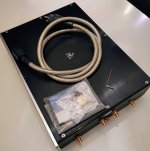
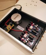
Orders now are open on 'Dark LED' passive filter/IV stage boards, ready built and tested or as a kit for the baseboard with a pre-built and tested filter plug-in. PM me and please don't forget to include your chosen payment method and location so I can quote you inclusive of fees and shipping.

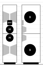
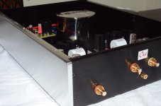
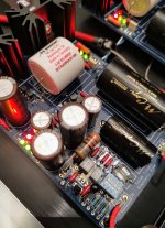
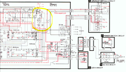
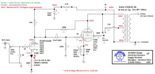
'Dark LED' combines a grounded base (discrete) cascoded stage followed by a 9th order LC filter, then passive I/V followed by a single-ended output buffer, designed to deliver lowest noise. The LC filter does the job of removing DAC images which, when in NOS (no oversampling) begin at 24.1kHz where this filter gives 40dB attenuation. Input sensitivity is +/1mA for 1VRMS out. The grounded base input stage presents a very low impedance to your DAC chip's current output (typically of the order of 5ohm) which helps it give of its best.

Here is how an 18kHz sinewave looks on a typical very-lightly filtered NOS DAC, compared to the filtered output of 'Dark LED' reproducing the same signal :

18k_NOS.png


18k_9thorder.png


Preferred payment method is via Wise which typically adds a 2% fee. Our receiving currency is CNY, alternatively USD or Euro. PayPal may also be used, in USD but will attract higher fees, 5.5%.

Price for a Dark LED built and tested unit including top-mounted filter board : 920RMB (~USD128)
A kit with most SMD parts pre-soldered at JLC, filter plug-in pre-built : 720RMB (~USD100)

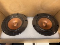
Physical dimensions: 72mm * 65mm, max height 25mm. Fixing centres : 60mm * 60mm, M3 holes.

Shipping is in addition and depends on your location and speed of service. Courier (FedEx, TNT, DHL) typically takes 8 - 10 days and e-packet four to eight weeks. Not all locations can be serviced by e-packet though.

FAQs

What else is needed to turn the built up Dark LED filter-I/V stage into a fully operational DAC?

You'll need, as a foundation, an existing DAC with a current output, +/1mA R2R chip. A few examples of suitable DAC chips are PCM56, PCM61, AD1860, AD1865 and PCM1702, these all have +/-1mA output in Iout mode. Your base could be an existing DAC board where you wish to bypass its on-board I/V (perhaps a socketed opamp) or maybe just a lash-up on perf-board with your R2R chip of choice. If your chosen DAC chip includes an opamp, be sure that this isn't in-circuit and the input to 'Dark LED' is being taken from the Iout pin of the DAC chip. With a socketed single opamp I/V the DAC Iout can usually be taken from pin2 (-ve input) of the socket when the opamp's removed.

Next you'll need a well regulated low noise power supply of dual rail +/-18V rated at 100mA or higher. An LM317 and LM337-based board set to the correct output voltages will be the bare minimum noise-wise. If you already have a single winding AC supply (an AC wall-wart) then 18VAC at 10-20VA would be in the right ballpark. Use a half-wave rectifier so you get both rails from a single winding or alternatively, a centre-tapped trafo. I don't recommend using switching supplies due to issues with common-mode noise, its very hard to filter out.

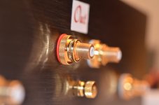
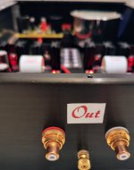
Third you'll be wanting some output sockets, typically RCAs so you can connect your Dark LED I/V to your amp or preamp. But your existing DAC may already have these, fed from its own filter stage.

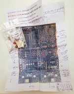
What will I have left to solder if buying the kit version?

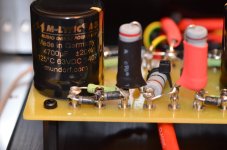
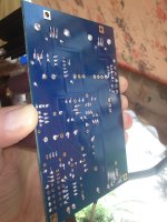
The parts JLC hasn't soldered are three NP0 capacitors, several 0.1% thin film resistors, ferrite beads (all 0805 size), SOT-89 transistors, 7mm dia inductors and the through-hole parts which are electrolytic caps and connectors.

What, if anything, is unique about Dark LED's design?

The LC filter is hand-built with in-house wound close tolerance gapped ferrite cored inductors, selected NP0 ceramic caps and the rest of the circuitry uses discrete (bipolar and MOS) transistors to deliver as low noise as possible. To this end, an SE (single-ended) approach is taken with I/V. The name 'Dark LED' comes from the use of infra-red LEDs as voltage references, which are very low noise indeed.

The use of IR LEDs helps reduce intrinsic and power-supply coupled noise meaning that a heroic ultra-low noise PSU isn't required, LM317/337 deliver satisfying results sonically at around 20uV audio band noise. Some technical background to the design can be found on my blog : https://www.diyaudio.com/community/threads/i-v-stages-and-noise.391189/post-7146239

WeChat Image_20230131174608.jpg

WeChat Image_20230131174629.jpg

Attachments

  • Dark LED IV Filter solder guide revA.jpg
    Dark LED IV Filter solder guide revA.jpg
    291.4 KB · Views: 737

Ideal bridge rectifier GB

Saligny.jpg


I had a look on the market, did not find one, so we built one. 🙂
We have designed a small form synchronous rectifier, aka ideal bridge, using modern ultra low Rdson mosfets.
It started as a small side project, but the results are so good that we want to put this in production and make it a standard product.
The advantages of such bridge are very well documented:
Active rectification - Wikipedia
http://www.ti.com/lit/wp/snva595a/snva595a.pdf
Synchronous Rectifier Circuit | Active Rectifier | Radio-Electronics.Com
http://peufeu.free.fr/audio/alim_mos_diode/


Linear product presentation.
https://www.youtube.com/watch?v=x74SSPgKiNA

While this video is about automotive product, the principle is similar.
https://www.youtube.com/watch?v=X5qFJ5XNi9A


Specifications:
- operates from DC to 600Hz
- AC operating voltage 6Vac to 51Vac
- DC operating voltage 9Vdc to 72Vdc
- Iq = 1,5mA
- continuous load current up to 16A or more depending on mosfet configuration.

Do not use centre taped transformers (and centre taped used as main reference ground).

The price will start from 35euro and go down with volume as we get parts in lower price.
Up to 100 units - 35 euro
Up to 200 units - 30 euro
Over 200 units - 25 euro

GB google spreadsheet is open till 1st March included
https://docs.google.com/spreadsheets/d/144EP7ZezFLFgZeNq8q8LCgoa5Lb6z94TKbopFC7S6aw/edit?usp=sharing

Regards,
Tibi
  • Thank You
Reactions: romanescu

3 Way DSP Amp

I assembled the following revision of the light version of the board, three channels of 100W PWM DAC with DSP ADAU1452.
Since there were some changes to the board structure, I decided to create a new topic to avoid confusion. Description of the previous version of the board here.


On this board revision, I add three auxiliary ADC inputs and two discrete input/output ports from the DSP. This expands the possibilities of external control of the chipboard.
To coordinate the operation of the ESP32 module and the DSP via the I2S port, a clock frequency detection circuit was implemented on the I2S bus; this was done to eliminate the transient process when receiving I2S data.
PDAC-100.png


An ESP32 module was added to the optical input/output board to implement wireless audio transmission via Wi-Fi and Bluetooth.

I_O optica SPDIF ESP32.png


TOP Plastina+ESP32.jpg


Starter projects for Sigma Studio.

Attachments

3Way DSP Amp + adapter for Dante AES67 board.

Aliexpress sells the Audio Network Transmission Interface A404 module, which supports the DANTE data transfer protocol.

Screenshot_2.png

The A404 module can be connected to the 3-Way DSP Amp using the adapter I assembled.

6.jpg4.jpg

This solution, using Dante software, allows you to transmit two stereo channels to the 3-Way DSP Amp via the Ethernet.

1.jpg

The price of the 3Way DSP Amp + adapter board without the DT AES67 module is $105.

Attached to the post is an archive of a folder with files for the starter project for Sigma Studio.

Attachments

Help with bias adjustment procedure on Parasound HCA-1000A

I could use a little assistance on the step-by-step to bias adjust my HCA-1000A.

I've watched a few "generic" YT videos on this for other amps and sort of get the basics, however the forum posts, videos and articles I've read have not been on this unit, or haven't provided enough detail for me. Some procedures have been close but when things state "measure from the output rectifier emitter" I sorta get lost. I know, I sound like an idiot. I just would like to learn.

I've got a DMM and some 'nads to give this a try, but I need some baby steps. If someone could point out where/what I should be placing my leads I'd really appreciate it, and then I can pay it forward someday.

What Should I Look for When Hiring a Video Production Company?

Hi everyone,

I’m looking to hire a video production company to create a short promotional video for my small business.

There are so many options out there, and I’m unsure what to look for in terms of quality, pricing, and reliability.

Should I prioritize companies with big portfolios or go for smaller, more affordable teams?

Are there red flags to watch out for when reviewing past work or client testimonials?

Any tips or recommendations would be greatly appreciated

especially if you’ve been through this process before.

Salas Folded Simplistic Phono (2014)

Hi all DIYers from Athens, Greece.

I' m selling my best diy project I made 11 years ago under the invaluable guidance of Mr. Nikos Salas.

I tried to use the best components I could afford (and find) at the time, inclusive of a sturdy aluminum case and a toroidal transformer (from a specialist in Poland).

I used silver WBT solder throughout and I made the best solders possible (see photo)!

The phono worked for approx. 18 months with a VDH The Frog (MC-high cartridge) with great results!

For a short period, I easily configured the insides for MM cartridge as guided by Mr. Nikos. Again, great sonic results.

Since then, the phono remained in this configuration but disconnected from my stereo due to a "different hobby orientation".

To be able to re-swap again to MC configuration I prepared a bag containing every component as well as detailed instructions. If I'm correct I didn't omit anything.. 🙂

Unfortunately, I cannot help in any technical question as I have forgotten everything about this project, sorry. Mr. Salas could help here if possible.

I'm asking 800 euros + shipping.

For overseas buyers: you should also provision for customs fees but I don't know if it's possible because I have no selling experience outside the EU and eBay.

Thank you for reading this listing,


Stavros.

Attachments

  • D70_3456 (66).jpg
    D70_3456 (66).jpg
    244.3 KB · Views: 153
  • D70_3461 (61).jpg
    D70_3461 (61).jpg
    279.3 KB · Views: 136
  • D70_3465 (57).jpg
    D70_3465 (57).jpg
    212.8 KB · Views: 139
  • D70_3468.jpg
    D70_3468.jpg
    256.3 KB · Views: 136
  • DSC_1095.jpg
    DSC_1095.jpg
    353.6 KB · Views: 133
  • IMG_20250310_212418~3.jpg
    IMG_20250310_212418~3.jpg
    409.6 KB · Views: 161
  • IMG_20250310_212841~2.jpg
    IMG_20250310_212841~2.jpg
    393.6 KB · Views: 160
  • IMG_20250310_212903~2.jpg
    IMG_20250310_212903~2.jpg
    522.6 KB · Views: 164
  • IMG_20250310_212914~2.jpg
    IMG_20250310_212914~2.jpg
    433.2 KB · Views: 142
  • IMG_20250310_212935~2.jpg
    IMG_20250310_212935~2.jpg
    398.2 KB · Views: 144
  • IMG_20250310_212943~2.jpg
    IMG_20250310_212943~2.jpg
    361.1 KB · Views: 139
  • IMG_20250310_213005~2.jpg
    IMG_20250310_213005~2.jpg
    362.9 KB · Views: 137
  • IMG_20250310_213025~2.jpg
    IMG_20250310_213025~2.jpg
    219.4 KB · Views: 135
  • IMG_20250310_213041~2.jpg
    IMG_20250310_213041~2.jpg
    436.9 KB · Views: 139
  • IMG_20250310_213119~2.jpg
    IMG_20250310_213119~2.jpg
    287 KB · Views: 130
  • IMG_20250310_213128~2.jpg
    IMG_20250310_213128~2.jpg
    307.5 KB · Views: 118
  • IMG_20250310_213142~2.jpg
    IMG_20250310_213142~2.jpg
    464.5 KB · Views: 108
  • IMG_20250310_213200~2.jpg
    IMG_20250310_213200~2.jpg
    313.4 KB · Views: 119
  • IMG_20250310_213552~2.jpg
    IMG_20250310_213552~2.jpg
    474.7 KB · Views: 144

PSU design/topology for portable HYPEX UCD400HG amp?

For my final bachelor's (EE) project , I've decided to build a battery powered PA speaker.

I am using a single RCF CX12N251 coaxial speaker as a driver and two HYPEX UCD400HG HxR amp modules to drive the woofer and the tweeter. For DSP I am using ADAU1701 board from wondom.

The main question for me is which route should I go in regards to power supply? Because the amp modules require +/-60Vdc (Bi-Polar).

For example, using two LiFePO4 12v batteries, and building two boost converters to boost them each to 60V, put them in series and use the middle point as GND? Ofc, trying to keep the noise as minimal as possible.

Anyways, if you have any experience or similar let me know. Looking for the "best" option for a class D.

Much appreciated!!

Tried unusual output stage with great results

Hi guys I have to share my unscientific experiment.
I got bored in my hotel room so I thought I try something crazy.
I pulled the opamps out of my Chinese R2R DAC and also out of my Accuphase c-3850 preamp clone boards from Ali that normally use NE5534 on the input.
Took some wires that fit nicely into the opamp sockets and connected all in in/out fashion.
1000240772.jpg

Result is very good. Dynamic detailed spacious sound.
All is powered by the Jan Didden silent switcher that runs off a 5v power bank. It puts out positive and negative 15v for the Accu boards and 5V for the Dac itself.
Listened for about 2 hours with only using up 1 bar of four from my 10a/h power bank.
I used my phone with USBplayer pro in bit perfect mode.
Absolutely stunning without any expensive opamps involved.
Gain is very high but for road use I will put the volume pot between the two Accuphase clone boards
If I use my tube amp I can probably get away with using only one Accuphase board.
  • Like
Reactions: pjasio253

TL graphic (THD and harmonic)

Hi all. Lately I've been working on a hybrid MLTL box that has a single 180 degree bend with no filling, just a completely empty duct to experiment and understand what happens inside. Previously I had built a BR box using the same speaker (without tweeter and without crossover). In both cases I made some measurements with REW obtaining graphs of SPL, distortion, harmonics and impedance, obtaining different results. I wanted to compare my results with those obtained by other people who have built transmission lines. In particular I am interested in the distortion and harmonics graph. I searched online without finding anything, this seems strange to me, perhaps I have not looked in the right places. What do you think?, are there people in this forum who want to share their data?. Ciao and thanks.

Philharmonic BMR in open baffle. Help designing 3-way crossover

I had the idea to combine the mid range and tweeter section of the Philharmonic BMR towers with an Eminence 15 woofer in an open baffle. Raal tweeter and BMRs would be in a MTM configuration like in the tower. I've built crossovers but always from kits or circuits that were pre-designed but never my own. I need A LOT of help figuring out what to do here? I have an inquiry out to Philharmonic Audio to see if they'll share some info with me or sell me x-overs but I've not heard back. I'm thinking I want to x-over to the Raal at around 3K hz (as specified in the Philharmonic BMRs) and a x-over to the Alpha15 at around 500-600hz. The Philharmonic towers use a 4th order Linkowitz-Riley x-over between the tweeter and the BMRs and a second order Linkowitz-Riley to the woofer. Ive heard that the x-over point on the Alpha 15 should be set much lower to get a higher actual crossover i.e. 100hz would give a x-over at 700hz for example. Not sure what I'd need to achieve a smooth transition between the Alpha 15 and the BMRs. Any help and advice (including you are in way over your head) is welcome. Thanks

Bridged amplfier circuit help

I've wanted to build a bridged amplifier as a project for a while, so I decided to first simulate a schematic in LTSpice. However, I got really weird results. The first channel looks fine, but on the second, the waveform doesn’t go as low as the first channel (I’m not sure how to explain it better), and the top is heavily distorted. Also, when using the Fourier function, the first channel gets around 0.003148% THD, while the second one is around 0.4–0.5%.
Also in lt spice simulation, i used the universal op amp 5 if that matters.

Here is an image:
sinew.jpeg

The green wave is the 2nd channel and the blue the first.


Heres the schematic:
schematiw.jpeg

Attachments

MTM sound characteristics

I have been reading a lot of older threads, and I have run across a number of negative statements about MTM driver arrangement.

I am considering an MTM layout for a future project. It will be a pair of 5 or 6 inch drivers with a conventional dome tweeter (no waveguide), with active crossovers. For the sake of discussion, we can assume I would use LR4 crossovers at 200 Hz and 2000 Hz. I have dual 12 inch woofer cabinets.

I do my serious listening while sitting in a specific comfortable location. I do not need a big "sweet spot".

I am interested in any opinions about the inherent characteristics of the MTM layout, both positive an negative. Obviously the MTM layout has a more narrow vertical dispersion than an MT layout, but beyond that I am interested in any theories about why an MTM layout would have a characteristic sound quality.

Thanks !

Introduction to designing crossovers without measurement

This tutorial is designed to get you started and tweaking a decent crossover… whether you're new to crossovers, or have built speakers before and are looking for a design method that relies on listening and doesn't require measurements.

The acoustic concepts apply to an active or passive crossover, since the needs of the speakers are the same in both cases. The simple but effective example crossover included here with formulas is of the passive type. With it you will achieve a much higher quality of crossover than possible using basic online calculators, and there is enough explanation to enable you to take it to the next level. Math has been kept light.

For illustration, I will be assuming a dome tweeter and a mid sized mid/woofer but with a little common sense this tutorial can apply to more than just two-way systems using typical drivers.


INDEX

Preparation
Post 2 - Choosing the crossover frequency - Part 1
Post 3 - Choosing the crossover frequency - Part 2
Post 4 - Directivity
Post 5 - Choosing the level
Post 6 - Baffle step diffraction
Post 7 - The design process

Design
Post 8 - Flattening the woofer's impedance
Post 9 - Flattening the tweeter's impedance
Post 10 - The woofer's crossover
Post 11 - The tweeter's crossover

Tweaking
Post 12 - Phase and diffraction
Post 13 - Tweaking the woofer
Post 14 - Tweaking the tweeter
Post 15 - Tweaking the system


You'll need to achieve these goals…
As this tutorial covers more than you may need, here is a list of the essential steps in case you don't plan on reading all of it.

1. Choose a crossover frequency based on your drivers

2. Choose the tweeter level (how loud it should be)

3. Flatten the impedances

4. Add the crossovers

…then on to tweaking. The rest of this tutorial helps in understanding how it works which will make the tweaking process more successful.

The goal of a crossover
Is to blend the sound from the two drivers (woofer and tweeter) so they work together as one. It may need to make the drivers as loud as each other, to divide the frequencies between them, and to correct or sidestep the limitations each driver will have.

Crossovers will not cut the drivers off suddenly at some frequency. There is a more gradual roll-off, somewhat like rolling a treble or bass control down. This means the drivers will be working together near the crossover frequency.

Monitor Audio AirStream A100 in 2025

I have just dismantled my new A100 as it stopped sending sound to the speaker terminals. You have to carefully remove the side cheeks. They are just glued in and they have a glass insert as I cracked one while praising it off. You then remove the 2 screws at the flaring and the case slides off easily. Nothing much to see in terms of blown capacitors but have to test the transformer. Everything else works perfectly and did until the sound stopped. I doubt if the sound issue is anything to do with the firmware but want to try it anyway but can’t find anywhere to download it. Has anyone out there got a copy they could send me? Thanks, Paul

Attachments

  • IMG_8344.jpeg
    IMG_8344.jpeg
    806.3 KB · Views: 30
  • IMG_8345.jpeg
    IMG_8345.jpeg
    759.1 KB · Views: 27
  • IMG_8346.jpeg
    IMG_8346.jpeg
    824.9 KB · Views: 24
  • IMG_8347.jpeg
    IMG_8347.jpeg
    890 KB · Views: 28

Soft start

Hi team, not really an audio question but I know there are plenty of brains around here… I need a very simple current limiter / softstart for an 18v DC motor, just need to slow the initial turn on hit, half a second would be fine. Motor runs at around 3-4 amps but start and full load would be a lot higher. Thought about an NTC or a two position switch with a resister that could be inline for a bit then change switch position to direct (Cut out the resistor).

What do you think?

Cheers

Have some Radian Neo745PB CD's + Ciare PR614 Horns to use in a 2-way build.

I have a pair of Radian Neo745PB compression drivers and a pair of Ciare PR614 Horns to mount them on and I am looking to building a 2 way system to complement them and finally give them a proper home.

I am in search of a woofer to start the design process and since I am located in Italy it makes sense to limit the field to the great speakers made here. 18 sound, RCF, B&C, Ciare, would be easy to source here. Here is my active list in a google sheet which your invited to add anything that might be of interest. LINK

How to go about marching a woofer to these compression drivers? I am open to suggestions but I was envisioning a 10" or 12" woofer. How does the response curve, the efficiency, the power handling guide the woofer selection?

The setup will be BI amped with some Powersoft Q3002's and I plan on doing active crossovers with a miniDSP or a rack mounted DSP such as a EV DC-ONE

The intended use is for a mix of home stereo, portable DJ setup, band practice, and just general PA usage. The plan is to add a sub at some point.

The budget is around 160EUR for each woofer.

Volume wise I dont have a hard constraint but something in the 40-55 liters sounds reasonable.

What other requirements or constraints am I missing to nail down a driver before moving to the cabinate design fase?

Thanks

Wide Directivity 2 way compact Speaker T34A Waveguide and Purifi 6.5 Aluminium

I have posted some simulations of the Bliesma T34A in a waveguide designed for wide directivity to very high frequencies, and some renderings of possible cabinet configurations using the Purifi 6.5 Aluminium driver in some other threads.

T34A 16mm 70 Deg Polar Norm 10 degrees.png


T34A 16mm 70 Deg Polar Curves Norm 10 degrees.png


T34A 16mm 70 Deg Mesh.PNG

Waveguide-Baffle-v2-copper.png

I am now making a concerted effort to actually build something that I can listen to 🙂

Finding time to finish the CNC I have been building (for a long time already) is proving hard and apart from aesthetics, I can make something simpler in appearance that performs pretty much as well with the already working tools I have. So a basic box with roundovers and a 3D printed removable waveguide will be the starting point.

Something more like this apart from the colour.

Waveguide-Baffle-v2 v1.png

In case it is not obvious to anyone, I should mention that Ath from @mabat was used in the design process for the waveguide.

For Sale Pair of Dayton Audio DC50FA-8 Classic Series 2" Dome Midrange, with different front plate, NEW, Never Installed...

OFF: Pair of Dayton Audio DC50FA-8 Classic Series 2" Dome Midrange, with different front plate (Used the original front plate on an other set of dome mids), NEW, Never Installed...
Check the picture. I think the link shows the specs. Was sold originally around 49U$each...

Asking 50U$ for the Pair (or 70$CAN50U$) + Shipping

I can ship at the buyer expense, local pickup permitted.
If using Paypal, add 3.5% Paypal fee (or use for Friend and Family)

Payment cash in person or by bank EMT transfer.

No interest, already packed, ut won’t move them, they are going away…

Thanks for looking
SB

Attachments

  • 20250308_103651.jpg
    20250308_103651.jpg
    242.7 KB · Views: 57
  • 20250312_142604.jpg
    20250312_142604.jpg
    214.7 KB · Views: 56
  • 20250312_142704.jpg
    20250312_142704.jpg
    272.7 KB · Views: 60
  • 20250312_142719.jpg
    20250312_142719.jpg
    265.7 KB · Views: 60
  • 20250312_142726.jpg
    20250312_142726.jpg
    253.4 KB · Views: 54
  • 20250312_142752.jpg
    20250312_142752.jpg
    213.7 KB · Views: 49

DIY Compression Drivers

NC535 inspired me to hack up my B&C coaxes and try to improve them here : http://www.diyaudio.com/forums/multi-way/317000-synergy-post5300335.html

Which led to this thread : http://www.diyaudio.com/forums/multi-way/317064-prosound-coaxial-hacking-post5300366.html

While hacking up that coaxial, a couple things occurred to me:

1) The tweeter that's attached to my B&C coaxials has a FS that's too high

2) I have a couple of 3D printers, I'm fairly decent at 3D modeling, so why don't I just build my own compression drivers?

ZuRYyu8.jpg

Here's my B&C DE5 compression drivers, which are part of the B&C 5FCX44 coaxial. You can see that it's a simple neodymium dome tweeter with a phase plug attached. Nothing too complex here.

jgk2YME.png


j0ZRNje.png


gGT3sv0.png


fTvej1f.png


Here's some pics of the phase plug that I made for my dome tweeters. This was my 2nd attempt, first one didn't work very well. It's largely based off of the tangerine phase plug used by Kef, which is an evolution of the Altec phase plug from fifty years ago.

Blade-Waveguide.jpg

Kef Tangerine

Altec-Lansing-Tangerine-Phase-Plug.jpg

Altec Tangerine


3oqBfHj.png

Here's the response of a TB neodymium 29mm silk tweeter, versus a Dayton RS28. Both are using the tangerine phase plug pictured above, and mounted to an 18Sound XT1086 waveguide. You can see the TB performs pretty well. I don't know if I have a bad batch of RS28s, or if it just doesn't live up to the hype. I have four of them, can't get particularly good performance from any of them.

WTHnQs0.png

Here's a comparison of the TB soft dome with and without the tangerine phase plug. Not a massive difference, but definitely an improvement. This measurement is at an identical voltage, with CD EQ and a high pass filter.

Nexus - World's Easiest Controlled Directivity Loudspeaker

I've spent the better part of the last year trying to make a speaker that could replace my Waslo Cosynes. I like the Cosynes a lot, but they're too big for my living room and my wife will certainly banish them soon.

I've made something like NINE attempts to replace it(1), and I keep failing. In particular, in my latest project, the waveguide was insufficiently small. Basically the speaker lost directivity control at 2khz.(2)

Frustrated by a pile of unfinished horns, I decided to do something different, and it worked out quite well.

4LhOcjf.jpg


1wHdYFd.jpg


5BGpqkt.jpg


It's the exact same drivers I used for Metlako and Celilo, but I'm uses a much smaller waveguide on the tweeter, and I've arrayed the midbasses.

kis7jyx.jpg


9rkJD9t.jpg


The arrangement is largely inspired by DNA Sequence speaker. From the patent:/url]

"Few conventional speaker systems approach an ideal of a high efficiency point source directional loudspeaker system. In fact, most conventional speaker systems are low in efficiency, lack phase coherency, and do not act as an apparent point source system. A speaker system in accordance with the present invention closely emulates a single point source. Embodiments of the present invention achieve this result by an advantageous arrangement of transducers. The arrangement of transducers minimizes the amplitude of the sound waves that can cause room reflections and the resultant distortion therein."

(1) [url]https://www.diyaudio.com/forums/multi-way/342019-metlako-affordable-unity-waveguide.html


(2)Celilo : A Small, Affordable Two-Way Unity Horn

For Sale Downsizing...getting rid of a bunch of drivers before I move

EDIT: Added location info.

I've been away from diyAudio for quite some time after work and life got busy. Now I need to relocate for work on short notice, and I need to downsize. It's time to let the half-dozen half-baked project ideas go to folks who are more likely to do something with the materials. Really, I should have done this a long time ago.

Right now, I'm just looking to move a whole bunch of drivers. They take up the most space. Don't really know how to price all this stuff, so please just make a reasonable offer, otherwise this stuff is going in the trash and that will suck. But it's not moving with me. Be sure to account for the actual cost of shipping from 98682. Some of them are a bit heavy, but I'd say I could probably ship any one set to you anywhere in the USA for about $25, maybe less. I will give you the lowest actual cost I can get for ground shipping through either USPS or UPS. Let me know if you have a preference for one service or another.

Local meetup in the Portland, OR metro area is OK.

Payment via PayPal

Everything has been stored in its original packaging indoors in climate-controlled environments, but please note that most of this stuff is probably 15 years old.

I didn't want to overload this post with pix, but you can see pix of everything here:

diyAudio For Sale (imgur)

DM me or post a reply to this message if you're interested in anything.

Thanks for helping me clear out my closet!! I'll be sure to update this post as things get claimed.

FOR SALE
----------------
SOLD Qty. 8 Dayton Audio DA135-8 5" Al Cone Woofer
SOLD Qty. 4 Dayton Audio DA175-8 7" Al Cone Woofer
Qty. 4 Tang Band W3-1335SB 8 Ohm Titanium Cone Full Range
Qty. 2 Hi-Vi B4N Al Cone Midbass
Qty. 4 Tang Band W3-315E Al/Mg 8 Ohm Full-Range
Qty. 4 Tang Band W3-593S 8 Ohm Paper Cone/Al Phase Plug Full Range

PCB order for Goldmun clone

Hi guys

This GB has been setup for the Thread : "The Very Best Amplifier I Have Ever Heard!!!! " # 174468


Please make my work easier by leaving information as follow :


Subject : PCB order for Goldmun clone
Content : <forum ID>;<email address (paypal a/c)>;M-99;P-99

There might be still some uncertainty about the pcb. But the price will be right if no change in pcb size.

Cost for protection PCB estimate to be $8 (should not exceed $9)

Will post status everyday after Oct 15

A Collection of 3D Printed Things

I've noticed that people have been printing out some of my waveguides, even though I never managed to actually finish a project. I've probably made five hundred things over the last few years, and many never even wind up getting documented, much less uploaded.

So I thought I'd pull up a few and post them.

Like a lot of my stuff, these things are a "work in progress."

You may need to do some reverse engineering, or just print the thing and see if it works.

I'm generally pretty good about getting the fit right, so most of these should fit whatever driver they're intended for.

I also have a github, but that interface isn't the greatest.

Instructions to use my GitHub here: https://www.diyaudio.com/forums/multi-way/342019-metlako-affordable-unity-waveguide-post5908380.html

Metlako: A Small, Affordable Two-Way Unity Waveguide

Theoretically, it's not possible to make a small, affordable two-way Unity waveguide.

The problem is the midranges:

There aren't many midranges that work well on a Unity waveguide. The ones that are usable tend to have a high FS and a low QES. Due to this, it's very challenging to get a suitable midrange to play lower than 300Hz on a Unity horn.(1)

Over the years, I've tried a gazillion different shapes for the midrange taps on a Unity waveguide. I settled on a shape that's largely inspired by the shape of the L'Acoustics DOSC. Basically the entrance to the tap is circle, and the exit is a ribbon. (2)

This specific shape allows for something seemingly impossible in a Unity waveguide, which is that you can 'push' the midranges to play much higher than they normally would.

With this innovation in mind, I wanted to find out if it's possible to make a small, affordable two-way Unity waveguide. The theory says it can't be done, but sometimes you can bend the rules.

fEOOrh3.jpg


2wF1AWe.jpg


Mabat's software is truly a game changer. It's literally cut down the time I need to make a waveguide by around 75%, and it's also allowed me to simulate them before I design and print them. It's unreal. (3)

OZrbtBV.jpg


WTM0ikO.jpg


Nd0BRO0.jpg


I came up with a new way to 3D print a waveguide that allows you to make one that's about twice as large as normally possible. Basically I slice the waveguide in half, and then I put one half inside of the other, like a Russian doll. The black waveguide was the biggest I could formerly print on my printer; the orange waveguide, hot off the printer, is about twice the volume. Same printer.

I have no idea if this is going to work. If it DOES work, it will simplify the process of making a Unity waveguide. Basically you will be able to have the midranges cover the entire spectrum. It will be a two way instead of a three way.

There HAVE been variations on this idea before:

1) Sound Physics Labs sold the "SPL Runt" which is a two way Unity horn. I could have gone that route by using a more expensive compression driver and midbass. Basically by using a midbass with a high FS and a low QES along with a compression driver that can handle some abuse. But I wanted to keep this project cheap; the total driver cost for all five drivers is under $75. Copying the SPL Runt would have quadrupled the driver cost, plus I don't like copying things 🙂

2) XRK did a two-way by putting a full range SB Acoustics at the apex of the horn. By basically pushing the tweeter down lower he was able to get it to play full range. Very cool! It blew my socks off when I saw it.

3) Art Welter has a two-way MEH horn that follows a similar recipe as the SPL Runt. (High FS and low QES on the midbasses along with a beefy compression driver.)

But I'm trying to take a different route, I'm trying to see if the geometry of the midrange taps can be modified to a point where they'll play full-range.

I don't know if this will work, but I'm eager to find out!


(1) https://www.diyaudio.com/forums/multi-way/88237-suitable-midrange-cone-bandpass-mid-unity-horn.html

(2) https://www.diyaudio.com/forums/multi-way/319698-unitized-image-control-waveguide-3.html

(3) https://www.diyaudio.com/forums/multi-way/279476-3d-modeling-tips-tricks-post5858286.html

NAD C320BEE

When I tried to adjust the bias I touch with the tip of the multimeter in one of the power rails and two fuses blown.
I replace the two fuses but every time I put the power on the same fuses blow again.
I'm not an electronic expert but I like to have some guidance from you guys and try to repairing it.
I'm only using the power section of this amp with a Yamaha pre-amp, but I do like a lot this power amp.
Thanks in advance.
Lica.

For Sale Fosi ZD3 DAC | Canare 4s11 | DIY bits and pieces bundle

1 - Fosi Audio ZD3. like new. comes in original packaging with all accessories and remote. everything like new. comes with two sets of op amps. comes with a set of XLR interconnect cables. $133.33 shipped friends and family

2 - CANARE 4s11 speaker cable. NEW. Gray. I have two cables segments. one in a little over 24 feet and the other a little over 12 feet. price all together $88 shipped friends and family

3 - bundle of random DIY components $44:
1- Quantity = 6 WBT RCA connectors
2 - quantity = 4 Neutrik XLR connectors. not all neutrik ins the same. this is the top of the line gold plated connectors black color premium ones.
3 - quantity = 2 DC power connector large
4 - quantity = 2 DC power connector thin
5 - quantity = 2 DC power connector medium
6 - 20x 1uF mica capacitor for power supply
7 - power on/off switch with LED indicator
8 - power on/off switch with LED indicator
9 - brass ground connector
10 - quantity = 4 ceramic tube connector
11 - aviator connector for building DC power supply 4 pin
12 - aviator connector for building DC power supply 2 pin
13 - quantity = 2 IEC power connector with fuse and on / off button
14 - big AC power distribution with usb A and C
15 - gold plated copper sliding connector with shield around 40 quantity

everything together $199 shipped conus paypal friends and family for EVERYTHING

pics:
Login to view embedded media Login to view embedded media

a hybrid SIC jFET: UJ3C120150 - any experiences?

In the 'search' for jFETs I found a hybrid SIC jFET: UJ3C120150 K3S
It is a 'normally-on jFET' combined with a driver mosfet:

This SiC FET device is based on a unique ‘cascode’ circuit configuration, in which a normally-on SiC JFET is co-packaged with a Si MOSFET to produce a normally-off SiC FET device. The device’s standard gate-drive characteristics allows for a true “drop-in replacement” to Si FETs, SiC MOSFETs.
1200V. 10A. >120W. zero input capacitance (sorry I dream: Ciss is actually rather high, then can't they handle that embedded driver better??). But at least: the curve is that of a jFET.
Has anybody any experience with this in the PASS community?
Or is it secretly an iGBT?

Attachments

For Sale Yamaha JA6681 Compression Drivers

* SOLD *

A pair of Yamaha JA6681B compression drivers featuring their famous patented diaphragms.

Close Serials #104036 and #104065. Original diaphrams visually inspected. Close coil resistance 12.6 and 12.5 ohms.

The absorbing foam (black) is present in one cover and was cleaned up from the other. Note that this foam disintegrates over time, and is best removed. It looks like one diaphragm was resoldered. Perhaps it was removed to clean up foam particles? (I am guessing).

Most important: The fingers of both diaphragms look fine: none is broken that I can see.

By mistake I threw away the front gasket of one of the drivers... A DIY replacement would do.

These outstanding drivers are becoming hard to find. Look at the reviews. For those of you who already own the JA6681: buy these as spares!

What's a fair price?
Let's say: drivers including diaphragms: 690 USD + shipping

North America preferred.

Pierre

PXL_20250117_194810830.MP.jpg
PXL_20250117_194749140.jpg
https://photos.google.com/photo/AF1QipNztMmcvfnCAusyUvT7JbHjKEbaGxlX2HF4CifF
PXL_20250117_194752052.jpg
https://photos.google.com/photo/AF1QipNztMmcvfnCAusyUvT7JbHjKEbaGxlX2HF4CifF
PXL_20250117_194242008.jpg
https://photos.google.com/photo/AF1QipNztMmcvfnCAusyUvT7JbHjKEbaGxlX2HF4CifF
PXL_20250117_194245342.jpg
PXL_20250117_194152310.jpg
PXL_20250117_194155913.jpg
https://photos.google.com/photo/AF1QipNztMmcvfnCAusyUvT7JbHjKEbaGxlX2HF4CifF
PXL_20250117_194144545.jpg
https://photos.google.com/photo/AF1QipNztMmcvfnCAusyUvT7JbHjKEbaGxlX2HF4CifF
PXL_20250117_194148344.jpg

2-way Driver selection, Will it meet my goals?

I'm in the designing phase of a 2-way setup with 1.4" CD and 10" Mid, with a passive crossover. My goals are 100-110db but prioritizing Sound Quality over anything. My last build (3way with decent drivers) was 2 years ago and I want this to be my final build and meet all my desires.

I intend on going with the 18Sound-10NW650 as my Woofer in a 1cuft vented enclosure tuned to 65hz, and the 18Sound-HD1480T CD with their XR1464C waveguide crossed at 800hz -ish.

I chose these drivers because I have a likeness towards 18Sound as a brand and grew up with the sound of their drivers, I've also had great personal experiences using their midrange drivers in a Car audio setting. That being said I'm not going to force myself to stick to their drivers exclusively if I have options that are far superior. I'm also considering the 18Sound-ND1460 and 18Sound-ND4015Ti2. From what I've gathered the ND4015Ti2 is much newer and also more expensive, I would like some input on if its worth it over the HD1480T. (Based on what I've read, I believe that it is likely worth it)
For the Mid I was also looking at the Beyma-10MC700ND, its more expensive than my intended 18Sound-10NW650 but it modeled similarly in a similar airspace. I would like input on if the Beyma driver would benefit me in any aspects of SQ over the 18-Sound driver. I intend to cross at about 70hz to my Sub.

For the Passive Crossover I plan on using a Linkwitz-Riley 24 dB/octave on both high and low pass. I did consider going with an active crossover since I use a MiniDSP Flex as my preamp but I don't plan on spending the $ on another MC7270 to pair with my current one, or buying new amps entirely.

I have no experience working with Compression drivers but have learned a lot from reading. Any advice for the build is appreciated 🙂

Need help fixing Technics su-v660 ( SVI3205 ic seems fine )

Hi !, I need some help fixing a Technics SU-V660 amp, ( it uses the SVI3205 ic that I read I can't get anymore to replace it ).
Amplifier turns on but no output , the speaker relay does not turn on.
  • The switches for A / B output work
  • No short circuit on the ic outputs
  • No short between the outputs and the Voltage rails
So I doubt the transistors in the ic are burnt.
Might be a problem with the protection circuit ? The SVI3205 ic does that ? , turns on / off the speaker relay.
Any ideeas what to do ?.
Relay measures fine, maybe the transistor and resistors around it needs to be checked.
Thank you, Bruno.


Service manual here:

Attachments

💥Still For sale Only a few Drivers and Cables left. New even lower pricing!!

⭐️So I want to Thank everyone who has bought from me so far. I greatly appreciated it. 💥So for a new update I’m Giving some new lower pricing on the Mark Audio and Fostex Speakers. I still have all the Gotham Cables for sale and more. I can meet up if need to. You can e mail with questions and offers at my E mail at the bottom of the selling post. You could make me in offer for every thing if you wanted to am not opposed to working something out. So Am still doing spring cleaning.

Pending/ 1.Mark Audio MAOP 11 Drivers. A new set never used or tested. Still on the box they came in. Am asking $300.00 a pair and buyer pays for shipping To the 48 United States.

Pending/2. Mark Audio Puliva HD 2 drivers in the copper color. Brand new in the box never used or tested. Am asking $50.00 for the pair and buy pays shipping.

Sold/3.Fostex FE126E and FE126NV Drivers Brand new Never used or tested. Stored in a good room. Am asking $125.00 for both pairs I will pay for shipping to the 48 United States.

Pending/4.I still have the Dayton Audio RS125 Aluminum Drivers in 4 ohm. In the box brand new never used. Am asking $40.00 a pair and you pay for shipping.

Amplifier and speakers together as a set for sale. Dayton Audios Blue Tooth 65 watt amplifier for sale with the Studio 20 speakers. Am asking $85.00 now. Local pick up or I can meet up. Shipping would be on the buyer.

Pending/I still have the frugal horn XL for sale. Completed. Binding post and wire you have to do your self. Dayton Audios binding post plates and new top of the line dayton Audio binding post. A $70.00 Value still in the blister packs. Dayton 13 gauge (o.f.c.) wire. You get 24 feet of it. as well. Am asking $80.00 for the set of boxes with all mentioned. I can meet up. Shipping would have to be up to the buyer.

Cables Still for sale.

RCA Cable for sale.

4. Mogami 2524 Wire at 24 feet $0.86 x 22 =$18.92. Am asking $10.00 for this cable.

Speaker wires for sale.

1. Redco 12-2 C-2 12 x2 Gauge wire $1.25 x 50 feet= $62.50 I paid. Am asking $37.00 for this cable.


Mogami

1. Mogami wire (o.f.c.) hook up wires 1 red 1 blue. I paid $60.00 dollars for both of them. Am asking $30.00 for the set. 50 feet each.

Other speaker cable brands for sale.

A..Whirlwind 4x12 cables at 26 feet $4.55=118.3. Am asking $80.00 for this cable.

B. CBI Power series 12x 2 cables at 22 feet $0.91 cents for $20.02. Am asking $10.00 for this cable.


Sold/ Belden 1313A 10 gauge 10x2 speaker cables 54 feet $3.30 =$171.60.
Am asking $100.00 and buyer pays for shipping. Thick heavy cables.


West wire I believe I bought a Redco a while ago. $0.45 cents a foot at 22 feet =$9.90. Am asking $5.00 for this cable.

Gotham Speaker Cables.

1.(50010) SPK 2x1 30 Gauge wire at $2.45 a meter. 52 feet at 15.82 metersz . I paid $ 38.38 . Am asking $20.00 for this cable.


2.(50150) SPK-GAC 13 gauge shielded wire. $6.00 a meter. 38 feet of this wire. It’s 11.582 meters. I paid $69.49. Am asking $40.00 for this cable.


3.(50025). SPK- 2x2 13 gauge wire at $4.75 a meter. 42 feet of wire. Is 12.802 meters $ 60.00 my cost. Am asking $35.00 for this cable.

4.(50040) SPK 2x4 11 gauge wire at $6.96 a meter. I have 47 feet and 14.326 meters of this wire 14.326 x $6.96 = $99.27 my cost. Am asking $70.00 for this cable.

5.(5026) SPK 2x6 9 gauge wire at $8.95 a meter x 18 feet =5.486 meters $49.10 selling it for $42.00 for the cable. I also have a 28 feet of this cable as well = 8.5344 meters $76.38. Am asking $50. 00. I will pay for shipping for these cables.

(Updated) 6.(50080) 2x8 8 gauge wire 8x2 at $16.30 a meter x 24 = $391.20. The heavest cable I have to sell. Come on a spool in a gotham Audio box. Am asking $290.00 and buyer pays for the shipping.

A.C. Cables.

1. (85055) Gotham Audio GPC 3x5 4 meters x a meter $24.85 x 4 =$99.40. am asking $70.00 dollars and I will throw in an a second (85005 cable ) 10 feet I will give with buying the first cable.


I have some new speak on connections with seals and connections for the speaker wires and input speakers ons. you speaker box as well. I paid around $70.00 Am asking $40.00 you pay for shipping.

Wire hook up connectors

I still have a lot of Banana plugs and spades and rca cable hook ups. Please E mail me for quality and brand. I have Dayton Audio and Gotham cable and street wires and another brand. I also have wire dressing up for cables and heat shrink tubing and y boots for speaker wire making.


I still have the solder fume fan and Digtal weller solding station still for sale. I have extra tips for the solding station. Am asking $100.00 for both. Buyer pays shipping.


I also have a heated dryer with different air tips brand new never used station as well. Am asking $50.00 for it. Buyer pays shipping.


Sold/I still have The Dayton Audio Dats v3 mint condition and I will thrown in the bass box pro and crossover pro with and the Winspeakerz all for $100.00. you play for shipping or we could meet up.


I also have the original woofer tester 2 and I will thrown the Subwoofer tools box program in a Tri pod and an acoustic egg piece with it as well. Am looking for $60.00.
Local pick up or meeting would be great.

Please E mail with questions on offers and shipping. Thanks for looking. Jeff

Attachments

  • IMG_6042.jpeg
    IMG_6042.jpeg
    741.5 KB · Views: 26
  • IMG_6045.jpeg
    IMG_6045.jpeg
    782.5 KB · Views: 28
  • IMG_6044.jpeg
    IMG_6044.jpeg
    683.6 KB · Views: 31
  • IMG_6041.jpeg
    IMG_6041.jpeg
    536.1 KB · Views: 24
  • IMG_6046.jpeg
    IMG_6046.jpeg
    592 KB · Views: 26

(Another) Philips CD303 adventure.

I bought some weeks ago a cd303 player, partially recaped, and in a general decent order (I think the dude said something about the drawer leds-i don't know). As I am one of those guys that blanket recap all things I dismantle the thing to make a list.
The surprise come a little later when after assembly started to sound very "synth-like" and craped out-there is a possibility that I inverted the "data" and "psu" lines from the servo bord, I did color marked the sockets... - can't really confirm it- but hey, not the first time that I did something stupid.
I did put some Caps back on the bord telling my self crazy reasons for it 🙂) but no the CPU from the servo was dead.
The worst of the worst a old rare cpu- and factory programed - at first I found in soume posts and video clips a dude that had a "soundtraces" blue bord with a atmel chip on-no luck there, never find who actually sells them. But again I stroke some luck and find a set of servo + decoding boards the seller accepted my offer and I was back I business.
Just replace The MAB 8440DP D011 and he plays once again.

(I know most people don't like full recaps but I do, on my original boards or the replacement ones there where not of the philips axial blue electrolyticss in good shape except the 1uF ones all half the value and with a esr of many many many ohms)

I have to say I bought it to recover some parts from it, as a while back I seen some dac boards that required this dac (tda1540)...

But now. OMG that mech 🙂) .... How can I not like it? and anyway not I have another two DACs and filter that at this moment have no reason to believe that they don't work.

Now:
Need to dismantle it again and clean it as it still dirty and I hate having to pealing dead foam with my finger tips.
Adjust the drawer as it is not quite centered
Find and Replace ALL el-caps from drwaer board and laser board + fine tune the laser (don't know how-I have the tools done it before but with a much better service manual... one that I could read🙂) )
Find a solution for the annoying the in the clip : Login to view embedded media I don't like the look of the orange or axial film caps eighter- I will pull some for proper testing
Decide what decoding board is "better" type C or type A and If they are replaceable without having to retune things...
I had something else to say-I forgot.

Any thoughts you have to share will be gratefully received.

Attachments

  • s-l1600.webp
    s-l1600.webp
    139 KB · Views: 45
  • IMG_20250314_212707.jpg
    IMG_20250314_212707.jpg
    547.4 KB · Views: 44

Ultra high spec opamp MC/MM phono, warp "elliptic" filter, line, headphone amps

Ultra high spec. opamp MC/MM phono, warp "elliptic" filter, line, headphone amps.

This is a project that has been on Audio Karma for about a year and has had a number of revisions, additions and upgrades.
There are about 150 of the units in various versions out in the field and it was repeatedly suggested by builders that a thread be opened in DIYaudio- so despite some reluctance here it is.
As the title suggests, it is opamp based, and is hardly unique, but it has some unusual features and has stellar specs and is pretty easy to build.
Some features:
1. Optional parallel input amps-
2x LT1115/AD797/OPA1611 or OPA1612 for MC
2x OPA1641 or similar or OPA1656/OPA1642 for MM
Cartridge load components can be altered without soldering.
2. 75us TC in input stage to optimize overload characteristic- approx. 28dB at rated -9dBv output at all frequencies up to greater than 50kHz with +/-15v supplies.
3. Additional standard RIAA TCs in output stage.
4. Gain partitioning/opamp choices made to keep negative feedback factor high over the entire audio range to minimize high order harmonics and many tone IM distortion.
5. Interstage TC added to compensate for the transition to unity gain of the input gain stage to maintain RIAA characteristic compliance. No unity gain transition in output stage due to choice of architecture.
6. DC offset correction in the phono output- so no coupling caps.
7. Polypropylene caps used in all of the signal paths.
8. Off the shelf SMPS used with input LC filter.
7. Extensive on board power supply decoupling.
8. MC and MM versions can be built with some component changes.
FET input opamps for MM version. Bipolar for MC.
9. 62dB gain for standard MC stage, 42dB for MM. Nominal sensitivity- 250uv @1kHz, 5cm/sec for the MC, 2.5mv for the MM.
10. RIAA simulated compliance c. 20mdB p-p, 20Hz-20kHz. Measured with non selected off the shelf components to be <50mdB p-p. Simulated worst case <100mdB p-p.
11. Unmeasurably low (limited by measurement system) distortion at rated output, including harmonic and many tone.
12. Phono Warp first order "elliptic" filter with vertical (L-R) rejection of c. 3dB at 140Hz and c. 36dB at 2Hz. Nominally 0dB rejection of horizontal (L+R) rejection.
12. Additional 10dB gain can be selected in the warp filter section to increase overall gain to 72dB/52dB.
13. Buffers for volume control and line driving added, 47 ohm output impedance.
14. Mono switch, no balance control.
15. Optional balanced output drive, 47 ohms/side.
16. Optional (separate board) OPA1656/LMH6321 headphone amp. On board heatsinking. Can drive loads as low as 16 ohms. Unmeasurably low distortion. Output impedance c.0.1ohms. 6dB gain.

Measurement system. RME ADI-2 PRO FS R with REW.
High quality boards available. Schematics, measurement results, BOM and build guides available.
Any interest?
  • Like
Reactions: inyashd

Simplest possible EL84 push pull amplifier

I was looking for the most simple EL84 circuit to get started and found something like this:
http://www.diyparadise.com/simpleel84.html

Am I missing something or is that website missing something or is it really possible to build a working PP amp with one OPT, two resistors and a pair of EL84? Has anyone tried it? What's going on here?

The schematic:

1659609515545.png

A second identical shorted loudspeaker as passive damped radiator

Hello, please help me to model and determine the behavior and distortion of adding a second shorted identical loudspeaker in a sealed box (vas 24l, fs 39hz, volume 20l) as passive radiator.

I tested because i had a spare identical loudspeaker around, and I like because I have very clean bass now, but not really sure how to model, and if I could damage the second speaker due to shorting its terminals.

I think it should be something like a sealed box with losses, something like a variovent, or a bass like air flow resistor.

Kegger / Blueglow KT88 - Building the best version money can buy

I am looking at building the Kegger / Blueglow KT88 SET amp and I would like to see how well I can make it perform with upgraded parts. And, well, it is probably not fair to say I am willing to spend every dollar possible on it, I am open to a significant investment.

I plan to start with Hashimoto output transformers, power supply and choke. For the coupling capacitors, I purchased Duelund CAST PIO SN-CU. I am also considering adding Audio Note silver tantalum non-magnetic resistors and Cardas binding posts.

For those who built the amp or have thoughts regarding the circuit design, what else would you upgrade? Would you only use AN tantalum resistors in select positions? I have also heard carbon based resistors are better for the grid and wire wound resistors are better for the plate load positions, do you agree and have recommendations re brands?

I am newer to building tube amps, but I have a fair amount of experience in HiFi and have a very resolving home audio system. This is my reason for wanting to maximize the design.

Thanks for your thoughts. Here is a link to the BOM Mark shared. A big thanks to him for all his work on this version! https://blueglowelectronics.wordpress.com/diagrams/

Attachments

  • SE-KT88 v7 Amp Only - Blueglow - Final Build.png
    SE-KT88 v7 Amp Only - Blueglow - Final Build.png
    45.5 KB · Views: 282

JABO KH-53 Kuleaksel Horn 53cm HIGHEND 1 PAR

Selling my Jabo 53 tractrix horns. I have been very happy with them in my active system. I have divided them 800 - 4500 Hz in a 4-way setup, but you can easily split it from 350 Hz and up into a 2-way.

Entry 2". Length 32 cm. Weight 3 kg per piece.

Adapters can also be included. This has a 1.4" to 2" neck.

I will pack them well and will ship them in 2 separate packages. Please contact me for exact shipping costs.

Price $300
P_20250222_055827.jpg
P_20250222_055910.jpg

P_20250221_192505.jpg
  • Like
Reactions: JRKO

Philips CD303 Comes Back to Life, But There's Still a Problem

Hello everyone! Hope you're doing well.

I recently bought a Philips CD303 that couldn’t read discs, and after a complete recap of all the boards, it seems to have come back from the dead.

When I first got it, the player powered on, but the disc would spin a couple of times very slowly and then stop. After replacing all the capacitors (Power Supply, Decoder, Servo, CDM0, and Side Panel boards), it now reads discs and plays them perfectly. The biggest improvement came after replacing the capacitors on the CDM0 board.

While I’m thrilled to have brought this gem back to life, there’s still one issue I’d like to share with you all in case someone has any ideas about what might be causing it.

When I turn on the player (cold), the disc starts spinning very fast for about 1-2 minutes. After this time, the disc stops, and pressing PLAY starts playback without any issues. It feels as though some component needs to "warm up."

Additionally, while playing a disc, the playback occasionally (though rarely) stops, and the disc halts. However, pressing PLAY again, playback starts again normally without further issues.

Here’s what I’ve observed:
  • The SAA7030 chip gets very hot, reaching almost 60°C.
  • The SONY CX7934 chip (the slim chip located on the additional board of the decoder PCB) gets even hotter, reaching around 66°C.
What’s interesting is that if, for example, I listen to music and then power off the unit, letting it cool down for about an hour, the same behavior occurs when I turn it back on: the disc spins very fast for about 2 minutes, then stops, and playback starts normally. However, if I power it off and back on again after just 5 minutes, I can play discs without going through the fast-spinning phase. It really seems like some component needs to reach a certain temperature.

I also own a working CD202. I suppose I could try swapping chips between the two units, but honestly, the thought of opening the CD202 drains my will to live… I hate those metal cages around the boards!

Any help or suggestions would be greatly appreciated.

YISHENG LM3886 BTL Amplifier Board

… or: is it possible to attain more than 200W from an amplifier based on LM3886 IC

Here is another project from my workbench. I was very pleasantly surprised with several amplifier projects based on chip amps, LM3886 and TDA7293. However, the main obstacle using these ICs is moderate, or should I say, lowish power output, about 60W per channel.

People persistently complain about the “poor bass” but I don’t think that the IC is the culprit. Inadequate speakers in combination with poorly designed amplifier boards are likely responsible for the LM3886 bad reputation in low frequencies. My measurements indicate otherwise: the IC is OK itself but it deserves better “working conditions”.

Obvious solution is paralleling and bridging, but, it isn’t so straightforward. Due to the lack of knowledge I have decided to use an existing design and turn it into a decent and powerfull amplifier. My choice is YISHENG LM3886 BTL Amplifier Board which implements paralleling and bridging to attain High Power High Fidelity performance.

One channel of this board is presented at the snapshot below. A lovely design, if I may say. I haven’t tried yet to reverse-engineer it. My intentions are much more modest. I want ro investigate the real world performance if this board and how to use it as a Hi-Fi amplifier.

First, I have investigated frequency response of the board and I have found out that test results are great indeed. Also, I have tested square wave response which are quite adequate.

Now, I'm testing its endurance on 200W 7.3 ohm dummy load. For time being I was able to run it at 125W constant 1KHz signal. I do really push it at the limits of thermal endurance.

Otherwise, the board is a real beauty, very well designed with wonderful layout. It is going to have from me a beautiful chassis.

More to follow...

Meanwhile, I have uploaded more photos of the amplifier board from my bench.


Please note that the board utilized four OPA2605 opamps and two pairs of transistord: 2sc2383, 2SD669, 2SC649 and 2SA1013. It appears that it is a bit more than paralleling and bridging. Let's see what it is
Photo-3.png

Photo-2.png
Photo-1.png

Attachments

  • LM3886 BTL.png
    LM3886 BTL.png
    108.7 KB · Views: 475
  • Like
Reactions: inyashd

4 ohm 18" LF driver recommendations

I'm in search of a decent PA/hifi type 18" LF/sub driver for a vented 160L enclosure aiming for -3dB @ low 30s. It would be nice to have 95+ dB sensitivity at an acceptable xmax to achieve at least 115dB down to F3 and possibly good F10.

Budget is up to $400-ish and available here in the US. Been looking at the B&C 18TBW100 and 18TBX100 as possible options. Neo would be nice but a ferrite motor wouldn't be out of the question. Already tried the 18NW100 but its specs weren't as advertised.

I've looked at the so called 18" Marty Cube design, which is roughly what I wanted but I'm open to anything comparable. I prefer vented over the popular horn loaded TL for more accurate, tighter low end. A larger vented box is a good compromise IMO.

Please reply here with any suggestions in line with my preferences and goals.

Crumpled foil surround

Last time, the danish sold me loudspeakers with fake plastic chassis that was really made of cheap magnesia cast. And now they're telling me that crumpled foil could add enough of stiffness to make a loadspeaker functioning.

Any opinions on that?

Assuming the +/- 20% of radiating piston area deviation claim is a joke to focus on possible relevance of cone surround (see partial screenshot from dayton ultimax indicating hat piston area doesn't really change due to rolling, but at the same time, getting stiffness force roughly linear in [un-]rolled area), what about aging crumpled foil then? According to wavecor measurements, even standard formed surround appears to have notable initial stiffness change.

Attachments

  • purify.png
    purify.png
    253.9 KB · Views: 136
  • dayton_surround.png
    dayton_surround.png
    80.3 KB · Views: 139
  • 20250324_165321.jpg
    20250324_165321.jpg
    411.1 KB · Views: 142

help on my 1st build

I had built a pair of 2ways about a month ago but had bought some pre-built crossovers. I have since been tying to learn how to design the xovers myself. By far the most difficult part of the process imo. I think I have it at least close and would like to get some opinions. I'll post a screenshot of the graph and a parts list. Also, there are no resistors in this design but I think I dont need them? I want to cross at around 2500. Anyway, any and all help and/or guidance will be appreciated. I will note that even though the video I watched on how to use this particular program said to use tweeter/woofer when doing a 2way. It wouldnt recognize my woofer unless I used TM. I'm sure its something I'm doing wrong but the results look like it might be done right?

WOOFER TWEETER
Ind: 0.76 Cap: 13.48
Cap: 10.76 Ind:0.87

system_xo.jpg
txo.JPG
wxo.JPG

Know anyone who can repair and align HLPL030020 laser head?

I'm building a Nakamichi OMS5 from a couple of parts units. One was dropped and has a major failure in the HLPL 030020 laser assembly - the prism that directs the beam fell off and was sitting in the bottom of the case. I'm curious if anyone out there could repair and realign one of these rare birds so I could have an as new laser - it would be nice to have the diode and photosensor replaced for a fresh start.

OMS5 Laser.jpg

What's the magic of 2N5551 / 2N5401?

There was an article in Nuts and Volts (10 2013) about a headphones amp with op-amp topology and class A output. Claims pretty good performance. The transistors used (except for the power stage) are 2N5551 / 2N5401. Those are high voltage transistors. Would be a good choice for high voltage power amp design, but this headphones amp is powered by +/- 12V.

Is there something else about these transistors making them particularly good here? Or general purpose transistors like 2n4401 / 2N4403 will work the same?

Protecting heavy stuff from UPS/FedEx/USPS...

Have you shipped heavy stuff with UPS, FedEx, USPS?

Even gotten an amp with bent fins, broken off handles, and worse... once I got a pair or small speakers that had broken woofer baskets!

Often the box looks reasonable on the outside, and the stuff inside looks reasonable well packed... but somehow... they broke something off.

And putting a FRAGILE HANDLE WITH CARE sign is just putting a bullseye on your box. It says, hey... drop this one from only 12 feet, not 20...

In the DIY world, I wonder why we can't get a double box package when we buy the case from Modushop. Some manufactures sell you that and shipping is not too bad as the empty boxes are light enough. This works with lighter stuff like preamps... but with 50 lb amps....

Anyhow, the last heavy amp I received was really well packed. Kudos to Randy. That was a 4U, 400mm box. Maybe he should post the "schematics"... Some plywood, some straps, surround it with foam and put it in suitable large box with lots of duct tape. It worked very well.

Attachments

  • Resized_20250121_174317.jpeg
    Resized_20250121_174317.jpeg
    190.1 KB · Views: 122

Damaged KEF Q150 - What are my options?

Hi, I was building new enclosure for my Kef Q150 drivers, I tried to take the crossover out by too much force and snapped one in half....... What are my options here? Not sure how I go about making a new one or repairing it. Cannot see anywhere where I can just buy a replacement?

Any help much appreciated, thanks

Attachments

  • PXL_20250329_214642816.jpg
    PXL_20250329_214642816.jpg
    858.5 KB · Views: 79
  • PXL_20250329_214621595.jpg
    PXL_20250329_214621595.jpg
    306.5 KB · Views: 73
  • Like
Reactions: Jeffrey 01

Member since 2019, first post.

Hello,
Over the past year or so, I've been fixing up some of my old electronics that were lying around. Completely restored a ReVox B750 Amp that I rarely use, new belts on a Beosystem 2500, full recap on a Bose Wave, and recapped 2 Squeezeboxes. One of the sqeezeboxes I can't get working, so I'll keep it as a parts unit for the display.

Next, I want to look at a Sony CDP-89ES that skips and an Enlightened Audio Design (EAD) DSP-7000 Series III DAC.
  • Like
Reactions: 6L6
Projects by fanatics, for fanatics
Get answers and advice for everyone wanting to learn the art of audio.
Join the Community
507,773
Members
7,888,042
Messages

Filter

Forum Statistics

Threads
406,219
Messages
7,888,042
Members
507,773
Latest member
pete2000