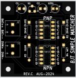
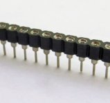
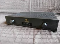
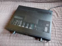
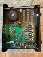
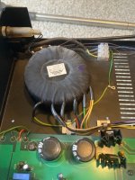
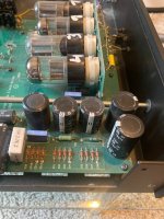
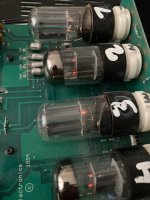
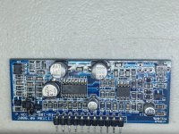
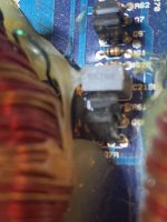
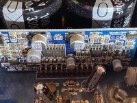
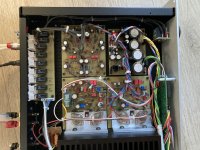
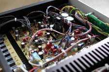
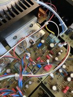
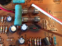
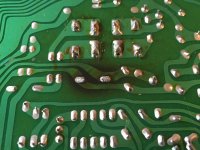
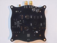
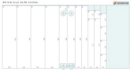
Why is this edge connector so hard for me to find?

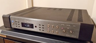
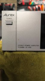
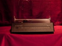
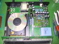
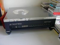
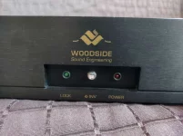
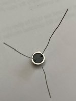
After 2 days of scouring Mouser, Digikey, image files, and various manufacturers, I can't find replacements for this 2mm pitch, 11 position, square pin receptacle/connector that include the PCB stabilizing clips at the ends. I've tried multiple keyword variations, and all I can find are right angle receptacles without the clips. I'm redesigning some burned circuit boards for a rare Audire amplifier, and would definitely prefer to replace this with the same configuration if it's even possible.

Any help much appreciated - thanks!

2mm Edge connector top.jpg

2mm Edge connector bottom.jpg

Hello

My name is Prezmo and I live in Poland.
In my free time, I do audio electronics as a hobby.
I came across this forum looking for information on improving the JLH1969 headphone amplifier.
I got my hands on a ready-made Gzlozone board, but the sound doesn't satisfy me. I'm looking for solutions to improve it.

Dipole speaker mimicing

Hi. Thanks for reading. After listening to a pair of dipole speakers I am impressed by the spaciousness of the sound. Two drive units connected out of phase with each other, which destroys the direct sound reaching the listener’s ear, so the listener only hears the reflected sound from the room’s walls, causing a spacious kind of sound.

But it seems to be an expensive build, with more drive units required. Is it possible to mimic dipole speakers with a non-dipole speaker, by using the out of phase back radiation in some way. I tried it by removing the back of the speaker enclosure, hoping the read radiation would destroy the direct sound, but it did not work well, the dipole speakers sounded much more spacious

DIY Dynamic Decompression of Music Tracks

I've been using Fabfilter Pro-MB for some time now to reverse some of the effects of music track dynamic compression during mastering...but not mixing, of course. I've found some interesting tidbits of information while using it:

1) Dynamic expansion with a good multiband upwards expander (like Pro-MB) is possible if the dynamics of the music track haven't been completely crushed into oblivion. In DR Database terms, this means that if the music track has at least a 6-8 dB rating using the "TT Dynamic Range Meter" (the standalone version or as a plugin for foobar2000), you have a reasonable chance of a good listenable outcome using multiband expansion. The maximum DR ratings that can benefit from expansion seem to be around 13-14 (dB-crest factor) on the DR Database scale. Any tracks compressed to lower dynamic range values seem to be "lost causes". It's much more productive to go on a hunt for a higher dynamic range version of the recording rather than trying to use a multiband expander.

2) The plugin settings used to expand tracks are usually most successful in increasing dynamic range in the higher frequencies of a track than the lower frequencies below ~100-200 Hz. This means that the crest factor ratings of the tracks from the TT DR Meter may not change very much (due to the fact that crest factor is really measuring bass dynamic range, but not really higher frequency DR), but the tracks themselves will present a much more crisp and forward sound quality for dynamic transients--like ride cymbals, crash cymbals, bells/cowbells, glockenspiel, all handheld percussion instruments (particularly latin instruments), string attack transients, marimba/vibe strikes, drums, and human voice transients.

3) The "steeliness" of string orchestras used in lush pop string arrangements and mass string orchestral scores (classical) will largely be suppressed if using the multiband expander carefully. This was a big surprise.

4) Any human voices, particularly female voices, will begin to sound much more realistic and without typical harshness that comes with listening to recordings having compression applied during mastering. This was the biggest surprise of all in my explorations using the expander.

5) The albums that respond most strongly and easily to multiband expansion seem to include those that had analog compressors applied during mastering (e.g., early-late 1970s albums), which apparently used continuously varying nonlinear compression curves without a sharp knee breakpoint/thresholding applied during mastering.

6) The music genres that seem to respond most strongly are funk, rock, folk, jazz (including smooth jazz), progressive rock with lots of drums/percussion, dance, and related genres. Those genres that seem to respond with more difficulty include smoother music genres having lots of midrange energy (i.e., ambient, new age, classical string orchestras, classical guitar, etc.).

7) All tracks that have used multiband expansion need to be adjusted before and after expansion using parametric EQ demastering.

__________________________________________________________________________________________________________________________

It's clear to me that the use of a multiband dynamic range expander is now standard equipment for my typical demastering tasks that I perform on most of my incoming discs.

I don't recommend trying to do expansion "on the fly" (without review and adjustment of expander settings track by track) unless extremely mild expander settings are used, which leads to barely audible subjective differences in the compressed tracks. Using an expander offline and taking a little time to get the setting right to get the best and most audible results is my strong suggestion in using these type of plugins. However, the task only has to be done once for the music tracks--then saved for future listening, instead of having to set up a custom string of plugins and parametric EQ settings each time a music track is played.

(My original text above was originally posted to another audio forum, albeit an unstable one, and has been moved to this forum to ensure its longevity.)


Chris

PC hardware experts

I'm looking for a PC hardware expert who can help me diagnosing and repairing a PC motherboard.
Mombo is an Asus P6T deluxe ver.2 socket 1366.
Mombo fail in POST procedure.
Nothing ,dark screen.
I have check with another good power supply,another graphic card, pulled memory,nothing.
Power supply start,CPU cooler fan start,nothing else,no beep nothing!
Any help out there?
I have done some measurements around VRM and I didn't see any voltage across electrolytic caps.

Attachments

  • IMG_20250323_170703.jpg
    IMG_20250323_170703.jpg
    606.2 KB · Views: 80

Speaker rebuild

I've got a Jensen 15" woofer and three Jensen tweeters someone had pulled from an Emerson console and sold online. The woofer itself has Emerson on it which likely means it was designed specifically for Emerson by Jensen or maybe just that Emerson asked for their name to be put on it.

I used the cabinet from a cheap 1950 Silvertone console that wasn't worth restoring (except the V-M Tri-O-Matic record changer which will go in my Magnavox CR-198C console) as the cabinet for the speaker. The only good thing about the cabinet is the piece of plywood I used for the speaker baffle.

The stock driver configuration of the Emerson console had the woofer in one spot and the three tweeters arranged in a triangle shape at an angle from the woofer. I arranged them as seen here. The extra hole was when I had a pair of dome tweeters on either side of the top tweeter. Didn't like how it sounded as it wasn't very good up close to the speaker given the distance between the two domes.

So I found a ribbon tweeter I had and used that which improved the sound.

Resizer_17235652347325.jpeg


Resizer_17235652224323.jpeg


I made a 6dB/octave crossover for the speaker as that's what was originally used except the woofer didn't have any inductor in series with it. The reason for the added tweeter crossed over so high is I didn't like how the cone tweeters didn't reproduce the treble up to 16kHz that good.


Jensen speaker crossover 2.png


The plan is to eventually have a new proper open back cabinet built and make it to where the ribbon tweeter mounts above the top cone tweeter.

Cannot decide if I want to paint it black like the baffle is or have it properly finished like the rest of the cabinet is.

Should I keep the 6dB/octave crossover or switch to a 12 dB/octave crossover as in will it make the speaker sound better or is it best to keep the stock crossover slope?

EDIT:

Here's a 12dB/octave crossover I've calculated. The .16mH, .32mH and .12mH inductors I could only get .15mH, .13mH and .33mH, however if I go with this crossover I will measure those and see how close they are to the calculated values, although if the inductors have a 5% or higher tolerance (website doesn't specify) they will be within the calculated value.

Jensen 12 dB speaker crossover.png

Buongiorno a tutti!

Good morning everyone,
my name is Alex and I come from Italy, and since we are on the subject of audio, I specify that I live in Sanremo the city known for the Italian song festival.
I have a PC with a b650 motherboard and a ryzen 7600 cpu, a xonar dx audio card and hivi t200c speakers.

I signed up to learn how certain mechanics work and improve my audio chain in the future.

Greetings from the Ligurian Riviera!

Sony Stereo repair - suspected dead STK

Hi all,

I'm trying to repair my Sony CMT-M373NT bookshelf stereo which has rendered excellent service as a USB sound device with my PC for nearly 20 years. 25W + 25W output, with 6R speakers

Symptoms:

  • System starts as normal, relay clicks, sound is produced, but:
  • Right channel has a buzzing/hissing sound and none of the actual signal. Constant volume, regardless of volume setting.
  • Left channel is 100% normal
  • Result is the same when switching speakers around
  • Same can be heard through headphones
  • With right speaker disconnected, the system can be used Left channel only with no issues
  • With right speaker connected, the system drops to protection mode within a few seconds

Looking at the circuit diagram in the service manual and knowing that these components are well known for going bad, I’m strongly suspecting the STK403-030 amp module. Anyone think I might be barking up the wrong tree?

1693383573409.png


However I can’t probe it in situ because of the way the system is built; the STK and all of the supporting components are masked by other closely stacked and rigidly interconnected boards. However with the board out and checked on the bench there are no dead shorts on any of the transistors or capacitors and no open resistors.

IMG_20230829_172840.jpg


I was planning to solder fly leads to the pins of the STK in situ and then reassemble the unit to allow me to probe voltage the STK pins with the whole thing powered up. Assuming that’s confirmed bad then a repair would be pretty straightforward if it weren’t for the lack of availability of these STK modules. They are listed on ebay and from China but it seems that more likely than not they will be fake, although they do look quite convincing, with the same moulded top cover.

1693385551481.png


Are ALL STKs subject to fakery? This system was bought in 2004ish so we’re not talking about parts that haven't been produced in 40+ years as with some models of STK. Does the top cap come off these easily? If so I could probably buy an ebay one, pop the lid and compare the internals with the original one, a fake will be easy to spot I assume?

Then as I’ve started reading I’ve realised that it’s probably fairly simple to directly replace the dead STK with a couple of either LM3886 or TDA7294. Could anyone offer some tips/pointers here?

As a hobbyist electronics tinkerer I’ve designed, built and coded many Arduino-based devices to do with supporting functions in car engine conversions etc so I’m no stranger to the skills required and I have a decent working understanding of the electronic principles at play, but the specifics of audio/amplifier design are beyond me at present.

Cheers!

Trying to decide on MarkAudio or SB Acoustics for MTM retrofit

Hi, I have a nice cabinet of a very closely spaced MTM. Stock drivers are ok but deep bass somewhat lacking for size of cabinet. The woofers aren't really designed for it like a more modern driver. A warm but "woody" kind of sound.

Trying to decide using 2x Mark Audio Pluvia 11s per can either in 1.5 way or 2.5 way with tweeter - or both with crossover switch!

Or, using SB Acoustics 17nac woofers in 2.5 way or mtm and a low Fs tweeter (must be small neo/small flange due to existing arrangement).

How are the Pluvia with bass? Is it worth using them as more of a woofer? They would certainly be the more artistic option as the cabinet is a darkish orangey kind of wood veneer. Roughly 40L.

Drivers need to fit in a 172-3mm rebate if others are to be suggested; slightly smaller can work too

90 issues of Audio Xpress and many others - FREE

Offered for free is my childhood collection of Audio Xpress and Speaker Builder magazines. There are 90 different copies of Audio Xpress, 10 copies of Speaker Builder, one copy of Glass Audio, one of Audio Electronics, and some random copies of UHF and Inner Ear.

I was lucky enough to have these growing up as a kid / teenager, and would be happy to pass that experience on to someone else. These are by no means in collectible condition, but they are all clean, dry, and ready to be enjoyed.

Also included is a copy of Mullard Tube Circuits for Audio Amplifiers and one copy of Audio Amateur Power Amp Projects.

Free to anyone willing to pick them up in the Ottawa area (downtown).

Cheers,
Owen

For Sale Budgie's Preamp PCB 2014

Hello,
I created the board using special software based on the published schematics and PCB photos!
Shannon Park (diytube.com) Unfortunately, his website and forum have been taken offline,
but I saved everything I need (e.g., firmware for the Arduino Nano).
I used the top side of the original board as a template, and that was relatively easy.
The back side was more difficult, as there isn't a decent photo of it.
And the back side also serves as the ground plane,
so you have to look at the schematic again for each component!
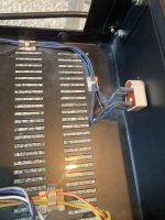
To protect the tubes and fingers, these things are available at aliexpress:hot:

A3950.jpg


audio Xpress:
Our DIY section also brings a great project from Shannon Parks, with its Arduino-based real tube preamp.
This is a simple 12B4 linestage controlled by a Arduino Nano board and the tube power supply is probably
the simplest in our magazine’s history: it uses a 24V, 1A desktop supply.


I'm only selling the boards. If you're interested, please PM me.

fdp1.PNG1 (1).PNGParksPh1.jpgAudioXpressCoverJuli 2014Web.jpg

Attachments

Build This MoFo!
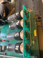
Pre-BAF appetizer project posted. Enjoy 🙂

Build This MoFo!

EDIT: (6L6, Jan ‘23) above link is dead, here is link to the article - https://6moons.com/audioreviews2/mofo/mofo.pdf

Hope to see you at BAF! Don't forget admission is free for everyone who brings a project.

Let us know what you're bringing in in this thread:

What are you bringing to Burning Amp 2017?

IMPORTANT NOTE: A Zener diode from the MOSFET Gate to Source is needed to protect the MOSFET from inductor "kickback" I got away without this when using MOSFETs with high maximum VGS and lower supply voltages, but had not anticipate the range of FETs, inductors, and supply voltage that might be used. Even when the stars align, it's too close to not consider the Zener mandatory.

There's already a place for this diode on the PCB sold here in the store. When my stars align, I'll update the article pdf.

In the meantime, my good mentor PRR has provided some illustrative filler:
https://www.diyaudio.com/forums/pass-labs/313649-build-mofo-279.html#post6368030
  • Like
Reactions: Bonsai

Did my first speaker measurement today - comments are welcome

Hi all

I am on a learning curve, and made my first speaker measurement today. I followed the great guide on Audiosciencereview Link on how to make Quasi-anechoic measurements with REW.

My aim is to get experienced with the needed measurement techniques, before i jump right into building my first speaker builds 🙂

I got the best measurements with the distance of 50cm, but all guidebooks recommend 1-2m. Gated window allowed ~5ms. I am sure i can improve that with better placement, and increased dampening in the room.

I would be happy with your feedback, tips & tricks etc.


IMG_1604.jpg

IMG_1603.jpg

Dali_56cm_1.jpg

Dali_56cm_2.jpg


Dali_56cm_3.jpg
  • Like
Reactions: kevinkr

For Sale FOSI ZD3 DAC | CANARE 4S11 | dayton woofers

ZD3 like new . in retail box. two sets of op amps, pair of xlr cables $133

CANARE 4S11 speaker cable. New. I have two lengths. one is 12 feet so you can make a pair of 6 feet speaker cables. the other is 24 feet so you can make a pair of 12 feet speaker cables. both are NEW. 4S11 comes in two colors black and gray. mine are gray. $88

Quantity = 3 Dayton Audio Designer series Paper cone woofers 6.5 inch.
two are tested and are in perfect cosmetic and functional condition. one is new. all three are perfect.
https://www.parts-express.com/Dayton-Audio-DS175-8-6-1-2-Designer-Series-Woofer-295-428?quantity=1

quantity = 1 Dayton audio measurement microphone NEW.
https://www.parts-express.com/Dayton-Audio-EMM-6-Electret-Measurement-Microphone-390-801?quantity=1

Bundle of random DIY components
1- Quantity = 6 WBT RCA connectors
2 - quantity = 2 DC power connector large
3 - quantity = 2 DC power connector thin
4 - quantity = 2 DC power connector medium
5 - 20x 1uF mica capacitor for power supply
6 - power on/off switch with LED indicator
7 - power on/off switch with LED indicator
8 - brass ground connector
9 - quantity = 4 ceramic tube connector
10 - aviator connector for building DC power supply 4 pin
11 - aviator connector for building DC power supply 2 pin
12 - quantity = 2 IEC power connector with fuse and on / off button
13 - big AC power distribution with usb A and C
14 - gold plated copper sliding connector with shield around 40 quantity

everything together: $111 shipped. I only accept paypal friends and family

Greetings Audio Junkies! I come in peace!

Hey everyone,

I grew up installing car stereos in the late 90's building custom enclosures, going to sound comps, car shows, etc. I've been out of it for a long long time but with a recent newer car purchase, I find myself hating the "premium sound system". So here I am to speak to other car audio enthusiasts, and get ideas on how to perfect a very complicated stock system. I also love reading posts on the latest and greatest home audio and studio audio equipment.

- Jeremy
  • Like
Reactions: AdamThorne

planet10-hifi miniOnken Plan-Set Subscriptions

____________________________________

(last revised 27-july-2022)

Advanced & comprehensive miniOnken plan-sets for the Mark Audio & for the new Fostex FFxx5wk are/will be available for a subscription fee. Not all are as complete as i'd like (and even those that are will keep growing) and some have grown so fast they need reorganization (so please excuse that).

Available for the [CHR70 (all)/CHP70.2/CHBW70], Alpair 6.x, Alpair 7.x, [EL70/Pluvia Seven/CHP70.1], A10x, A12/12p, A12pw & Fostex FF85wk, FF105wk (which includes a set of mods to use FE103 SOL), FF125wk. Some FF165wk plans exist (same as A10p enclosures (with adjustments) so more can be quickly done) FF225wk under development (based on same enclosures as Alpair 12pw).

Rectanguar & trapezoid miniOnkens with vents on the side, simplier Classic Golden Ratio, and Compact Floorstanders are included in the plansets where appropriate. Custom designs done to cover client needs are also included. Other variations for wall mounting, more centres, and dedicated mid-tweeter use. And more. Included are details (where appropriate), cut-plan suggestions, tips, visualizations, and other information wher eit is useful.

Many enclosures have been standardized, with vent & driver details changing as needed. For example there are 6 widths of trapezoids (so far) with height changing to accomodate different volumes.

Plans are not a 1-shot deal, but a subscription (except for the Monster miniOnkens). I am always adding to them, and doing updates for specific clients (ie if you have available material that is not a thickness i have already done drawings for, i will generate plans for that thickness, or if you need a variation of a box to fit a specific need). Plans are also updated as questions & suggestions come in. There is much work to do, but any specific client needs will be taken to the top of the queue.

CAD plans for specific pdf pages can be provided on request.

Plans will be revised as needed for when drivers are revised.

Plans based on Mark Audio drivers are $25 USD each for EL70/P7, CHR/CHP/CHBW, A6x, A7x, for A10x, for A12x, A12pw. A subscription to the entire series is $80.

Plans are $25 USD each for FF85wk, FF105wk, FF125wk, FF165wk ar ein place & FF225wk is under development and will be the same price, A subscription to the entire series will be $80.

Tandband W8-1772 $25

HiEnd miniOnken plans for Lowther PM6A/C, Voxativ AC1.6, Tannoy HPD 385 are $50

Condensed plans (single drawings in most cases) for the Monster miniOnken series $10USD:
for Goodmans Axiom 201, Diatone 810 II, Dayton PS180/220 , Eminenence 12LTA, Tandband W8-1808, Tannoy Gold 12", Tannoy 385, Audio Nirvana 10 Cast Frame, Audio Nirvana 10 Neo, Airborne 6.5

Sealed box for ScanSpeak 32w-4878T $25

Canadian clients add appropriate GST/HST.

Plan-sets for other drivers will be done as appropriate drivers (ones we like and think are good value) come along.

The 1st paid planset was going to be for the Fonken with FE127, but the discontinuation of the driver stalled that one. That planset, as far as it got, is available on request for free.

dave

µMar-KenSET build

Hi folks,
I'm planning a small new pair of speakers for my desk.
The design of the “µMar-KenSET” appeals to me (size / appearance) and also the driver used.

Can anyone tell me where the F3 is, the bass is sufficient for desktop use and whether the cabinet would also be suitable for coupling a tweeter from approx. 1000hz?

As I'm new to the forum I can't write to anyone directly yet, maybe planet10 is reading along and could get in touch with me regarding the construction plan.

Best regards 🙂

PO89ZB, an inline DC filter for SMPS wall warts. Preamps, HPA, Korg NuTube, etc

Quite a few recent line-level projects here on diyAudio, are using Switch Mode Power Supply ("SMPS") wall warts to convert mains AC into the DC needed by audio circuitry. To name a few recent examples, the Starving Student II headphone amp, the First Watt H2 effects box, the B1 Korg NuTube preamp, and the Amp Camp Preamp+ (with headphone amp) are all powered by external SMPS warts. It's definitely a trend.

However, the 50-350 kilohertz switching circuitry inside SMPS modules, does make some members nervous. These folks are very concerned that high frequency noise on the DC supply, could compromise the sound quality of audio circuits. They desire a DC supply having very little high frequency noise, or, ideally, none.

I felt that, IF these pieces of audio gear could tolerate an additional 100 - 150 milliohms of resistance in series with their DC power supply, THEN we can build passive filter circuits to eliminate much of the SMPS high frequency noise. Admittedly I only studied their designs briefly, but I did come to the conclusion that all of SS-II, H2gen, B1Korg, and ACP+ can indeed tolerate an extra 0.15 ohms in series with the DC supply. So why not build a filter with a little extra series resistance, and see what happens.

After some experimental tinkering, the circuit schematic in Figure 1 took shape. It has two stages of LC filtering, built 100% with through-hole components for easy soldering. Noise attenuation at 50 kHz is about 40dB (i.e. 100x); while at 200 kHz, noise attenuation is about 65dB (1700x). Input to output DC resistance is about 100 milliohms on the PCB. Then we need to add the resistance of external wiring (about 16 milliohms per foot for AWG-22).

The filter circuit is laid out on a small PCB, 35mm by 40 mm (Figure 2). After stuffing, soldering, and attaching I/O connectors using blue and white "fly wires", the PCB looks like Figure 3. The first prototype unit was mounted inside a half size Altoids (breath mint) tin, using Kapton tape to electrically insulate the metal box from the rear face of the PCB. Then a piece of double sided foam tape keeps the PCB firmly attached in place. See Figure 4.

After the board is seated inside the enclosure and the I/O wires are pulled into their final position, two generous dollops of hot-glue are applied where the wires pass through holes in the enclosure. The glue keeps the wires fixed in place, and reduces the chances of abrading or scraping off the insulation.

When ordering the PCBoards, I told the fab to build them extra-thin: 0.6mm. This didn't cost extra money, and it seems not to have slowed the order's speedy progress through the fab. Figure 5 is an ungainly attempt to show just how slender the boards truly are. After all, the thinner the PCB, the smaller an enclosure it can fit into. Since it costs nothing to build extra-thin boards, why on earth not?

With this PCB and these components, the design limits are 48 volts maximum and 3 amperes maximum. You shouldn't exceed 48V, no matter what the current. And you also shouldn't exceed 3A, no matter what the voltage.

Speaking of components, here is a Parts List. It's plain ordinary text holding comma separated values. You can copy and paste it into a file on your computer, and then MacGyver the data into any format you wish. Surprisingly, there is even a Wikipedia article about MacGyver.

PARTS LIST

Code:
2.1mm x 5.5mm male plug,xyz,490-PP3-002AH
2.5mm x 5.5mm male plug,xyz,490-PP3-002B
2.1mm x 5.5mm female jack,xyz,490-PR-002A
2.5mm x 5.5mm female jack,xyz,490-PR-002B
470 uF 50V capacitor,LS 5mm and Diam 10mm,80-ESH477M050AH4AA
2.2uH 7.5A 0.10R inductor,LS 5mm and Diam 9mm,652-RLB0912-2R2ML
68V unidir TVS 600W,DO-204 pkg,576-TP6KE68A
953ohm 1% 0.25W res,xyz,603-MFR-25FBF52-953R
0.04R 5% 1W current sense res,LS 12mm,66-OAR1R040JLF

A quick note on DC barrel connector plugs and jacks: the individual parts sold by Mouser and DigiKey, have unusually small solder-lugs to connect external wires. That's because these parts include a removable, screw-on housing which takes up valuable space. {Unlike high volume wall warts, whose plugs are simply molded plastic} So the Mouser/DigiKey plugs and jacks only accept smaller diameter (lower current!) wires. Tinker with them and decide whether you find them acceptable. If not, you can buy thick 2.1x5.5mm (and/or 2.5x5.5mm) extension cables, then cut each end to 15 cm length. Amazon also carries individual cables with quite hefty (AWG-18!) wires attached to plugs or jacks. Here is an example to start your search adventure (the first link) But honestly, there's a fantastic implementation in post #935 of this thread that is worth considering.

This filter circuit includes polarized (electrolytic) capacitors and a unidirectional diode. Thus it only works correctly when the input is positive with respect to ground. Most SMPS wall warts are arranged this way, with the center terminal of the barrel jack "Positive" and the outer ring of the barrel jack "Negative". However, a few pieces of audio gear {I'm looking at YOU, pioneer batch B1 Korg NuTube preamp!} have chosen to make the center terminal Negative and the outer ring Positive. For those weird situations, be VERY VERY careful to route the IN, OUT, and GND terminals of the SMPS filter PCB, to the correct pins of the barrel jack and barrel plug.

Ingenious builders, I am confident, will dream up amazingly clever ways to mount and package these PCBs -- in astonishing configurations that bear no resemblance to a pedestrian candy box. The nicest thing you can say about half-size Altoids tins is probably, "they are both cheap and easy to obtain." Innovative, talented people will do better, astoundingly better I'm sure. edit- and my prediction came true, see post #935 of this thread. Thus I request that you disregard half-size Altoid tins and please DO NOT CLICK the following link (the second link)

The unique identifier for this board is "PO89ZB" followed by "-A" indicating revision A. I've put that identifier into the thread title, for easier searching in future months or years.

Gerber files for the rev-A PCB are attached; anyone can send these files off to a PCB fab, and get as many boards built as they like, with my blessings and good wishes. Please consider giving away or selling any excess boards that you've accumulated, to other members of diyAudio.

HOWEVER, rev-A does not include mounting holes on the PCB. Member carsten.witt has modified the Gerbers to create a PCB which does include mounting holes. These Gerbers were used to build the boards & kits sold by the diyAudio Store. Please visit post #407 of this thread (here is a LINK) to download Gerbers WITH mounting holes.

_

Attachments

  • SMPS_filter_schematic_revA.png
    SMPS_filter_schematic_revA.png
    26.3 KB · Views: 14,267
  • Ruler_PCB_plug.jpg
    Ruler_PCB_plug.jpg
    262.2 KB · Views: 13,240
  • PCB_and_wires.jpg
    PCB_and_wires.jpg
    268.6 KB · Views: 11,255
  • Annotated_assembly.jpg
    Annotated_assembly.jpg
    378.7 KB · Views: 9,897
  • very_thin_board_edges.jpg
    very_thin_board_edges.jpg
    268.6 KB · Views: 11,835
  • PO89ZB_A_Gerber_Files_SMPS_Inline_Filter.zip
    PO89ZB_A_Gerber_Files_SMPS_Inline_Filter.zip
    14.2 KB · Views: 1,255

Optimation PA-250AC Lab-Grade Audio Amplifier

Hello everybody!

I was recently given this amplifier, an Optimation PA-250AC, and I would like to know if any of you all know anything about it. As far as I can tell, it is NOS, or near NOS. It even came in its original shipping box! I also have all the tubes for it and the manual. First of all, this thing is a monster and weighs in somewhere around 90 pounds. According to the manual, it is a lab-grade audio amplifier, capable of delivering 250 watts at 0.01% THD! At reduced power, the frequency response is 5 to 100,000 Hz. It takes 8 EL34/6CA7s on the output stage. It also has 3 impedance outputs, 3.75, 15, and 60 ohms. It's also capable of delivering a constant-current or constant-voltage output, and the meter can measure the output voltage, output current, or the plate current of each individual output tube. It uses both negative and positive feedback to keep distortion to a minimum, and even has overload protection. Overall, it sounds like a pretty amazing amp. Also, the front panel is hinged so you can easily access the circuitry. I know tube amplifiers pretty well, but this thing is far more advanced than anything I'm familiar with.

I've included a few pictures of this beast that I took before I installed the power tubes and played with it. First of all, it sounds incredible! It goes down to 5 Hz with ease, and it has power to spare.

If any of you know anything about this monster, or have had any experience with one or something like it, please let me know! Apparently it's pretty rare, since I couldn't really find anything about it on ol' Google, but just because something is rare doesn't mean it's worth anything.

Attachments

  • Optimation Front.jpg
    Optimation Front.jpg
    484.2 KB · Views: 854
  • Optimation Rear.jpg
    Optimation Rear.jpg
    483.5 KB · Views: 792
  • Optimation Inside.jpg
    Optimation Inside.jpg
    481.6 KB · Views: 835

Curtis from Boston, MA

Hi, I live in the Boston area. I have a CJ amp and an LTC Aero dac, wharfdale bookshelf speakers, and a very ancient Myriad CD-100 player, all of which I love. I am building a Tubelab SSE amp. I have all the parts and am doing final assembly and check out. I am also interested in the Nelson Pass Nutube amp, bc it represents a resarection in tube technology. I would be interested in audiophile meet-ups in the greater Boston area. Curtis

New Member Introduction

Hello. I am retired and live in the greater Boston, MA area. I started updating my stereo system (still playing vinyl) and am looking for info/advice on items such as amplifiers, phono preamps, DACs and other ancillary equipment. I began this project when I recently inherited a six-tube(?) amplifier built from a kit. Completed, I think, except for attaching the case covers. When get permission, the first question I will ask is "How long a stick should I use first time I turn it on." Thank you.
  • Like
Reactions: Pano

For Sale Audio Precision System One SYS-322A Audio Analyzer + Burst Option + APIB USB Adapter

This is the Audio Precision System One SYS-322A Audio Analyzer, this is the dual domain DSP version where you can test both analogue and digital signals, as well as DSP FFT Spectrum Analysis. In addition with Burst option you can generate additional signals like Square waves.

It also come with both APIB PCI card and USB Adapter (adapter alone already cost $375) from Duke Aguiar (ex Audio Precision engineer), his USB Adapter even works on my Windows 11 PC (also tested working via Parallels Desktop (Win11) on Mac M1 Pro).

Despite its age its still a very capable equipment, Stereophile uses same model for their measurement before upgrading to Audio Presion SYS2722. Even British Loudspeaker Manufacturer ATC still uses it for their active speakers amplifier testing: .

Originally bought used directly from USA and still in working condition, convertible to 100V, 120V, 230V, 240V Mains voltage.

I'm located in Kuala Lumpur, Malaysia.

Asking for $1850 (negotiable) + shipping fee (depending on your location, I will try quote with both EMS and FEDEX shipping fee)

If you have any queries feel free to reply here or drop me a message ;-)

Attachments

  • IMG_0732 Large.jpeg
    IMG_0732 Large.jpeg
    175.3 KB · Views: 123
  • IMG_7467 Large.jpeg
    IMG_7467 Large.jpeg
    260.1 KB · Views: 115
  • IMG_7468 Large.jpeg
    IMG_7468 Large.jpeg
    293.9 KB · Views: 116
  • IMG_7469 Large.jpeg
    IMG_7469 Large.jpeg
    233.9 KB · Views: 121

A better TMB Tone Stack

Hi, i don't know if this was done before but i made a improved version of the classic TMB tone stack making it a bit more versatile, this version has few tweaks to make the treble pot more useful and independent from the middle potentiometer, for example, the frecuency response isn't flat anymore when the mid is up and the rest at 0, now the treble can boost and roll off high frequencies. The middle control now attenuates ~25 dB compared to the 15 dB from the original circuit, also the bass control is more noticeable now thanks to the better frecuency separation from the rc filter.

How does it work?, is pretty simple, C1(the 470pF one) and R1(33k) are now two T high pass and low pass filters, this separates the highs and lows so the controls affect only the proper frequencies. R3 Bleeds the low frequencies
from the treble pot when its necessary, if the bass knob is up R3 is off so more lows and mids stay in.

It maybe good for mods because you keep the pots the same values, you just need to replace and add some resistors and caps.

I hope this can be useful to someone that doesn't like the original TMB stack 🙂, personally i think its more practical and sounds better but that's subjetive, if you try it any suggestions will be very appreciated.

Green : New
Blue : Old

Attachments

  • TMB_Improved.png
    TMB_Improved.png
    17.8 KB · Views: 628
  • TMB_Improved_mid0bass0treb12.png
    TMB_Improved_mid0bass0treb12.png
    17.5 KB · Views: 571
  • TMB_Improved_mid0bass12treb0.png
    TMB_Improved_mid0bass12treb0.png
    16.5 KB · Views: 384
  • TMB_Improved_mid0bass12treb12.png
    TMB_Improved_mid0bass12treb12.png
    20 KB · Views: 379
  • TMB_Improved_mid12bass0treb0.png
    TMB_Improved_mid12bass0treb0.png
    18.1 KB · Views: 363
  • TMB_Improved_mid12bass0treb12.png
    TMB_Improved_mid12bass0treb12.png
    16.6 KB · Views: 291
  • TMB_Improved_mid12bass12treb0.png
    TMB_Improved_mid12bass12treb0.png
    16.5 KB · Views: 447

Hello, I just burnt some resistors and some More!

30 years old guitar player here also novice electrician. I like enjoy fixing stuff but this time I need help. My amp is not in a good condition I read 33V dc on speakers.. Ouchh..

First it was only one resistor that burnt by plugging the amp, after changing it then others smoked, then I noticed the wire going to power transistor is deattached. I replaced old tip29/30c's with modern 40/41c's, 204/207 pairs with also 547/x pairs, 2n3373 changed with mj15003 but I am still hearing the buzz and It's still 33V dc at speakers... What is wrong bias? I am just tired. I double check transistors BCE, EBC all right, I don't know what to do anymore... Feeling overwhelmed.
Amp is HH vs musian 100
At first I lost that 10 R at the 48 volt supply then bias one, then 1k feedback resistor... I am open to suggestions..

Attachments

  • IMG_20250312_214801.jpg
    IMG_20250312_214801.jpg
    812 KB · Views: 111
  • IMG_20250312_214825.jpg
    IMG_20250312_214825.jpg
    389.4 KB · Views: 115

SAE Mark IIICM defective resistors

I have been in the process of resurrecting my old SAE 3CM amplifier. It's been more problematic than I expected. It hadn't been fired up for 30+ years so I bought a re-cap kit and swapped out all the electrolytics before I punched the "on" switch. The re-cap job went OK, although I first had to un-do some "improvements" the previous owner had done. Like remodeling old houses, you never know what you're going to find once the studs have been exposed.

Initial testing after the re-cap job looked OK -- the driver board's idle-current measurements were good and the output voltage offsets were reasonable and could be adjusted to a few mV.

But longer-term operation revealed a problem in one of the channels. The output would limit on the negative portion of a test waveform (1KHz sine). And I also observed that the bias voltage went down, from the normal ~2.1V to about 1.85V. I suspected a problem in the Darlington VASes so started my troubleshooting by measuring the emitter resistors on the Darlington emitters (R24 & R25, see below). The 3CM uses symmetrical NPN/PNP LTPs that drive two Darlington pairs, one for the + side and one for the - side. So there were two emitter resistors to measure: and BOTH measured quite high. The schematic indicates that the resistors should be 62 ohms. The one on the + side measured over TWICE that, and the one on the - side measured about 90 ohms! That is far beyond the 5% tolerance the SM specifies for those guys.....

For a sanity check I also measured the 10 ohm resistors that are used to isolate the driver board's supply busses from the output board supplies. They were spot on.

I also measured the emitter resistors in the "good" channel and they also measured high, although not as bad as the failing side. The SM indicates that the R's are carbon film types. Visual examination didn't reveal any indication that the resistors were subjected to excessive current, and I didn't see any obvious mechanical damage.

In normal operation those 62 ohm resistors should be dissipating far less than 1/2 watt. I think they are that size so they will survive if/when a short circuit condition occurs & Q11 or Q12 turn on.

I'm puzzled why the resistor on the plus side is the worst, but the output waveform clips on the negative side. That channel initially works -- more or less -- but then starts clipping after it's warmed up. So there may be a thermal intermittent situation. My next test will be to monitor the resistances while I heat them with a hot-air gun.

The main point of this post, however, is to ask folks if they have seen a similar problem with old carbon film resistors spontaneously failing like this. If not, there's a good chance something else is going on that is over-stressing those resistors. The other thing is: if those went bad simply due to their age, it doesn't bode well for the other CF resistors in there. And there are a lot of them. Replacing all of them is not my idea of a fun time.....

Mark

PS driver board schematic below:

1740941743620.png

Kind of new to diy audio … again!

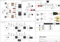
I somehow stumbled into diy again after nearly 25 years have passed since my last project. On an online market I came across a guy, who had started to build up an Nelson Pass F5T V3. The project was started together with a friend of him, who unfortunatly passed away. Because of this circumstances he didn`t want to work on this project anymore. Since I`ve been always attracted by class a amps, I decided to buy from the guy what was already there and to finish the project. By searching the internet for scematics and more information about this amp, I came across the forum and joined as a quiet reader of the threads regarding the F5T some weeks ago. As I need a good preamp too, this led me to the BA3 threads and currently supplies are coming in with the material I`ve ordered. My plan is to get everything done during winter and I`m really eager to hear the difference to the 6550 push pull tube amp I use right now. Of course I hope to get some help from all of you here if needed. 🙂 thnx in advance!

MAT02, 03 Elektor preamp schematic

Elektor has in time past published two hi-end preamps using MAT02 and MAT03 dual transistors for the differential pair using +-15volts supply; one was with a DC offset nulling preset somewhere in the negative supply line and the other was with a servo using OP77.

I have somehow lost both the Elektor issues but would like to have the schematics. I have three assembled boards of the one with the servo. I would also like to try out the easier offset nulling arrangement.

Could someone please send me a scan of the entire articles OR if someone wants to sell their copies of Elektor containing the above, I will gladly buy them.

Thanks,

Bad news for Ripole sub builders :-(

The inexpensive 12" Peerless SLS woofers work really well in Ripoles. In fact; the SLS 12 is my all-time favorite $75 woofer.

I regret to report that the Peerless SLS 12 and XLS 12 woofers are no longer available at Parts Express without a 100 quantity min-buy. I called Parts Express about this and was told that the manufacturer (Tympany) imposed the 100-qty min-buy, not Part Express. Apparently; these woofers are being phased out but I don't see any comparable replacements for them on Tympany's website.

The discontinuance of these woofers seems non-sensical to me-- rather like Logitech discontinuing their Transporter streamer.

If anyone is interested in doing a group min-buy; count me in for ten.

new here and want to share my build Jmods with Mforce subs

Hi everyone,
I am 21 years old and will finish carpentry school this year in Amsterdam. I started enjoying sound systems after going to a party of kantarion. I was pulled in to the world of sound en subwoofers. I started cooking up a plan in my head of what I wanted. I knew it needed to be bass heavy but also pleasant for the ears. In the 3 years my school takes I did multipel internships. one was at Solosound. This is an electrostatic speaker maker in the Netherlands. This is where I learned to really listen to music and what it takes to make it sound good. sadly you can not use electrostatic speakers in a club setting because of the moister that builds up from sweating people. An other internship I did was at the Fiction Factory, this is where I learned to use a 5 axis cnc.
I was talking with IVCU from kantarion about what kind of tops I wanted and my first idea was the classic X-tro. but ended up choosing the JMODS from John White. this was because I liked the idea of a meh. I still have acces to the cnc and I already used it in a prototype I made of the meh jmod. was super nice to do all the weird angels easy peasy with the saw on the cnc. so now that I choose the tops I was looking at what kind of sub/ kick bin. JW did say in the paper that a kick bin won't be needed but I am planning on mostly playing EDM so kickheavy music and what I like about kantarion is the punchiness.
I was looking into the NNNN sub that goes down to 16 hz and was like yesss infra subwoofers is what I want. After some digging I found the Mforce drivers from powersoft. I looked at them and was like what the f*ck is this. got pulled into the idea of a system that is really special. so I contacted a distributer that had them. he was super nice and gave me the email of ALL, he is working on a diy design for the mforces. Went to visit ALL this weekend and was super nice talking to him and sharing details. because I still have acces to the cnc I am planning on making multipel prototypes out of mdf for the MFORCEs. (the tapped horn of ALL, standerd EDM sub and DV sub from powersoft.) currently writing this is the car on our way back to nl with the Mforce drivers in the back. I am here on diyAudio to share my findings with everyone about the drivers and the measurements from the boxes, about the road I am taking for the system. (also get some help if I don't understand anymore.) did not choose on kick bin yet because I maybe want a 2x15 or a few singel 18s, this will all depend on how loud the big boys wil get. I will be in Milano the next few weeks for the design week, wil start building end of April. Will keep everyone updated.

Versatile Hybrid Preamp w. Power-Amp Option

Experimental Hybrid Preamp Design

By Kurtus Richter

Here is a collection of diagrams for a very versatile hybrid guitar preamp, meaning a preamp involving both solid-state and tube-type circuits in one project. The reasons for hybridization are as follows. (1) With purely analog circuitry, tube-amps sound better than solid-state amps, and which also applies to preamps. (2) Hybrid preamps allow for the mixing of a nearly pure input signal from the solid-state circuitry with a distorted signal from a tube circuit in which the tubes are deliberately overdriven. (3) Tubes have a slower slew-rate than solid-state devices; by orders of magnitude. In fact, a guitarist who plays very fast scales can exceed the slew rate of the tubes in a tube-type amp, resulting in indistinct attacks of individually picked notes, heard as a muddy sound, but solid-state devises have slew rates that cannot be exceeded. Consequently, for analog circuits (i.e., no digital processing involving modern sampling technology), one remedy is to use two kinds of amps, or two preamps; one solid-state for attack definition, and one tube-type for the tone. Hence my design for a hybrid preamp.

1743454672370.png


The block diagram above illustrates how different circuits in my Hybrid Preamp can be connected together, though other arrangements are possible. I have deliberately placed input and output jacks on each of the solid-state subcircuits, and recommend they be retained, in order to maximize versatility. This gives the user the ability to connect the different circuits as desired and insert external devices, such as stomp-boxes, between any two such circuits, though the tube circuit is self-contained, since it is a distortion circuit inspired by the Garnet Herzog unit made famous in the ‘60s and ‘70s by guitarist Randy Bachman, who used it on hits American Woman and Takin’ Care of Business.

But first I show the input preamp, which has highly user-adjustable parameters, and can also be considered a distribution amp, where one output can be a direct signal sent to the Mixer, another can go to the solid-state 5-Band Tone Control or the Booster, or both in series, and the third to the Tubes.

1743454718418.png


The table in the diagram lists the low corner frequency that can be set by switches S1 and S2, according to the user’s personal taste. For instance, for deep lows, use the 20 Hz setting, but for no lows at all use the 240 Hz or even the 400 Hz setting. The gain of the preamp can also be adjusted from 2 to 200, depending on the setting of switch S3 and the position of the Gain control. High gain, in conjunction with a sufficient setting of the input Level control allows for enough signal voltage to be sent to all three preamp outputs so there should be no trouble adequately driving subsequent circuits. Below is a 5-band active tone-control circuit, which is of my own design.

1743454771800.png


Ordinarily, 3-band tone controls work fine for the electric guitar. Yet, I designed the above 5-band control for users who want greater adjustment of the sound of the solid-state circuitry. There is also volume control on the output of the Tone Control circuit, and a Booster circuit has been provided, with its own simply tone-control, to help the signal from the 5-Band Tone Control compete with the signal from the Tube Circuit.

The 5-Band Tone Control’s frequency bands divide the audio spectrum by 5, labeled here as Bass, Lo Mid, Mid, HI Mid, and Treble. The approximate frequencies are:
Bass < 250 Hz, Lo-Mid 250 – 500 Hz, Mid 500 Hz – 2.5 kHz, Hi-Mid 2.5 kHz – 10 kHz, and Treble > 10 kHz.
But, of course, the user must set the positions of pots by ear to compensate for personal taste and how the human ear hears different frequencies.

Next up is the Booster circuit.

1743454857869.png


The booster has four controls; Input Level, Tone, Gain, and Volume. The Input Level control is needed to keep the Booster from being overdriven if it is to be used cleanly, but will also allow it to be overdriven if desired. The Tone control here only affects the highs, the Gain control adjusts the amount of boost, and the Volume control sets the circuit’s output voltage. And here are some active filters; one low-pass with a high cutoff, and one high-pass with a low cutoff. In series they form a 2-stage audio band-pass filter, to mitigate unwanted subsonics and ultrasonics generated in the other circuits. They can be used separately or in series in any order.

1743454930100.png


And we have a 4-input mixer, to mix-down as many as four different signals. And while the project is designed to provide three channels, one direct, one amplified, and one for the tube circuits, there is a fourth input to the mixer in case it’s needed.

1743455040413.png


The added mixer input is provided in the event an external splitter is used for some reason between any two stages and the user has an extra signal to be mixed with all the others. Below I show the power-supply and the pinout diagrams for the ICs used in the solid-state circuits. This supply is only for the ICs. The tubes have their own supply.

1743455082377.png


Note: A builder of this project may wish to make two or three of these supplies, each providing voltage to only two or three ICs, to keep from overtaxing a lone supply.

1743455197389.png


As said, the Tube Circuit is my version of a Herzog distortion unit. It is in fact a single-ended low-wattage guitar-amp in which the output tube is used as a preamp tube, for the purpose of overdriving it to get its distortion sound. The tube-type sub-circuits are given as follows. They must be treated collectively as one channel.

1743455247271.png

1743455267619.png

1743455282352.png

1743455300016.png


For a power-amp build to go with this preamp, consider the following resources.
A Complete Guide to Design and Build a Hi-Fi LM3886 Amplifier - Circuit Basics
Audio Amplifier Boards & Modules Amp Kits | Mojotone Amp Maker: Guitar amp kits
Amazon.com: 1 pc LM3886 Amplifier Board Power Amplifier Audio Amplifier OPA445 high
Voltage Version : Electronics

As an example, however, I copied a power-amp design below, or the builder can keep the power-amp separate from the preamp, according to personal preference.

1743455371400.png


1743455391521.png

1743455416092.png


1743455440317.png


Should anyone build this project, know that I have not built it in order to test it, so it must be considered EXPERIMENTAL CIRCUITRY all the way. Also, the builder must assume all responsibility for the outcome. I cannot be responsible for someone else building this project.

Comments welcome here, and/or send me an email. hkurtrichter@gmail.com

Getting accurate measurements in the worst measurement space

This past weekend I did a talk on how to get good measurements when you don't have somewhere good to do it.

I designed and build a small sealed reference speaker in the UK using a B&C 12NDL88

20250310_164159.jpg


I got some measurements outside fully calibrated in half space:

20250320_214951.jpg

20250320_220754.jpg
20250320_221422.jpg
20250320_221431.jpg


I then measured it at 8.49v to account for the 3m and 1w at 8 ohm

This got me this result:

1743440576392.png


I wish I had done more sweeps and a bit slower to get it a little smoother but I was in a bit of a rush getting prepared to come over to Berlin for the Hackathon.

I also measured a duel 12" reflex box outside in half space to compare it to.

On the following graph there is one very uncalibrated measurement of the duel 12" reflex which is the purple at the top, one measurement that is the half space measurement of the duel 12 reflex (half space so +6db) then the final lower purple measurement is the corrected measurement from above with the reference box.

Measurements.jpg


As you can see from the graph above it gets you very close using the reference speaker to calibrate but the space I measured it in wasn't too bad.

When I got to berlin I borrowed a 12NDL88 and rebuilt the reference box.

In the workshop I used possibly the worst space I could find to do a measurement to see what results I could get using a 12" tapped horn:

20250330_153024.jpg


1743441170859.png


These were the uncalibrated results:

1743441248179.png


As you can see there isn't much you could do with these measurements as the room was tiny and there was a lot of reflections.

After processing the results using my outdoor half space measurement:

1743441347675.png


As you can see the measurement has been cleaned up to the point of being extremely usable, it would be possible to EQ this flat and time align it to other speakers measured in the same place.

I think after testing this with the other measurement it is very important to get the measurement environment as similar as possible, measuring indoors without the background noise and other things changing seems to work really well.

Another factor is I found a sub to measure with a similar baffle size whereas that could add some distortion to the measurement, the duel 12 reflex was cleaned up reasonably well just off by a few DB, which I think was from me rushing and not measuring it properly. I thought I had calibrated it all but in my rush it was a good 15db too high haha.

Over the next few days I will release my outdoor measurement for this box and the dimensions of the sealed box for anyone else to build. This should allow anyone to get really good measurements without needing to find a massive space outdoors.

You can do this in your living room and get to within +-1db

Also using this subtractive method will allow you to in theory use any microphone and not calibrate anything and as long as you keep it all the same between tests it will calibrate it to my measurement

Another note is I had been messing around with REW before this and forgot to reapply my mic calibration, it doesn't adjust it too much but I will try and get a better measurement of my reference box, it won't change it too much though as it is already pretty flat.

All the presented measurements have no smoothing or windowing.

Another note would be that the 12ndl88 isn't the best for this but it was a driver that I owned and someone I knew in berlin owned so we could test this.

I was given this Idea by Kyle from Neuron AV but I couldn't find his profile on here to tag

Yet another Adcom GFA-555 cry for help

So, my Adcom 555 journey started in 2015. I picked up an early rackmount version of a GFA-555 for 300.00. I had never seen one like this one, the speaker connections on the back are not the the red/black variety, but a reddish brown for both the positive and negative.

Upon receiving it, I took it to Jim Williams (Pro audio upgrades), who did his thing on the driver board, and the main PSU caps tested as good.

I hadn't used it much, but late last year, I started to use it more with some JBL 6332's. One day one side went out. I opened it up and I saw there were 4 fuses, which I carefully ordered the same type and replaced them. All was good until one day, one side would make a pop sound and then volume on that side would get really low, and then come back intermittently.

I found a local guy that took a look around, checked some values on some caps, and said he repaired "30 things" and tested another 250 things. He charged me 150.00.

I got the amp home and it sounded great! i was playing it at relatively high volume and then, POP again, signal gets low. Out of anger, and smacked the front of the amp around the power switch, and loud static, and it came back to life. Something is loose.
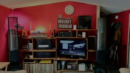
I have built some studio style mic preamps and a compressor back in the day, so I am not an expert, but can get around a bit. I called the guy back to see what his input was on this symptom, and I wasn't that keen on taking it back to him, and he did lift a trace while he was working and I now have an extra wire on the bottom of the board....He advised me to get a piece of wood and poke different parts of the unit to try and isolate where the loose connection is. I used a 6 inch long wooden q-tip and started poking around while audio was passing through. When i hit one of the fuse holders on one of the output boards, POP! I found the issue!
I disconnected the amp and re-flowed the solder on all four fuse holders, as well as rough them up a bit for solid connection. I also re-flowed some joints on the outputs. Felling like I really accomplished something, I decided to check the bias before I closed it up. As I was too impatient to wait for clip leads to arrive, I tried it with regular leads and while on one of the emitter resistors, it slipped and sparked, shorting to i believe either the orange or white wire pad right near the 2nd emitter resisitor. After this and before I turned it off, the driver board started to smoke just a little bit, so I immediately shut it off.

I did call another local guy, but his wait time was 6 weeks. After looking at may ADCOM troubleshooting/check out vids on you tube, and reading every thread here on Adcom 555, I have decided to tackle it myself!

When powered on the left distortion LED on the front panel stays on. I powered it down and used the multimeter to check for resistance on the output board ( not sure if it's the pos or neg side, but its the one with the green transistor at the top. There is no resistance on the Toshiba TO3's so I know that at least one of them is bad. I plan on taking this board out and removing all of the TO3's to test. One of the things bugging me on this is that the board does not have the silk screening, and the layout is close, but doesn't match the one that I have downloaded, and I have looked high and low for this board layout and cannot locate. The only one I couldn't get to was hifiengine, as they are closed for new registrations.

I would also like to address if possible the resistor that the guy moved to the bottom of the board and the wire trace.


Side note, while I was beating myself out for shorting the unit, i started to look around for another 555 locally, and found one 3 exits from me for only 280.00. I went to see and hear it, it his guy was the original owner! Unit is super clean, and is also an early version but with the red black horizontal terminals on the back. I opened this one when i got home, and it is pure untouched! so at least I have a back up if something goes south, but my hopes are to get the non functioning unit back on it's feet, and then may replace the electrolytics on the driver board, the one safety transistor that is a known possible failure point, and the filter caps on the bottom as Jim Williams did to my 1st unit.

This is a great community and I'm kind of glad I found it, as I'm starting to get the electronic bug again! Thanks to all in advance!

PXL_20250203_002935100.jpg
PXL_20250203_003011213.jpg
PXL_20250206_013809848.jpg
PXL_20250202_221133447.jpg
  • Like
Reactions: Freedom666

Tweak amplifier performance for a certain power level

Hi,

When tweaking an amplifier for best performance (THD / spectrum analyzer) we see that the performance is different for each power level. With my average speakers (for example Pied Pipers) the actual power needed is barely higher than 1 watt. With most music and listening conditions 100 mW will be fine. The amplifier I'm still working on (KT150 PP) will easily give 75 Watt per channel, so I have a lot of headroom (more than ever will be needed).

What is a good rule of thumb to determine on which power level to "put" the best performance, keeping in mind the speaker efficiency. At 1 Watt (as in my case)? Higher? Lower? For 1 Watt I got THD below 0.10%, so I'm already pleased with the results.
What are your experiences with this?

Regards, Gerrit

Another “what kit” thread!

As per the title, looking for options for my next build.

This will be a build for my Son so will be a pre-designed open source kit as it needs to work.

He has a “media wall” cabinet with space for his Yamaha Hs7’s either side of the TV. So requirements are -
  • Passive Crossover
  • Open source available kit
  • Max volume 15L with 220mm wide baffle
  • To be used on a Media Wall so needs to work close to the back wall (or in a book shelf)
  • Likely to be sealed or be able to be modified to have a front port (circular or slot)
  • Budget £1000 for drivers, crossover parts and hardware (wood available), UK based.
  • Will be used for a mix of TV and Music (ranges from Pop/Country to Prog Metal and Metalcore).
  • No sub at the moment so need reasonable bass
  • I would prefer something with a more dynamic sound than laid back and has a broad and deep soundstage (probably difficult in this placement).
  • Room is a UK living room so approx 12ft x 15ft and 8.5ft ceilings with listening distance approx 8-9ft firing across the short distance.
Doing a bit of research it seem that the Scanspeak Revelator 15W (all four versions) is the favourite mid woofer for this size cabinet and there are around 10+ designs out there with a wide range of tweeters. The Carmody Carrera, Gravesen Ellam (XT and Flex are open source), Ego IX, Zaph ZD5, HiquiSpeak, Klan and Ton Scan Monitor, Audio Excute Revelation Two Monitor (+mk2), Intimates (x3 different tweeters), Skaldo are just a few of the designs out there. I have costed up most of these and they come in under budget. The Ergo IX seems to be the obvious choice as it is design for near wall use.

The crossovers vary quite a bit from a first order electrical with no capacitor on the tweeter (other than a 500uF protection cap), second order, second woofer/third tweeter and a number use a zobel or notch to manage tweeter impedance or shape woofer response and a couple use a ladder delay circuit.

Others I am considering are Jef Bagby’s Revolution / Revolution mini (especially the new Textreme versions), SB Bromo and Ara TX (simplified 1st order crossover with notches).

So, has anyone got a preferred 15W design that stands out above the rest or are there other designs I should be considering?

Thanks in advance for the comments and replies.

For Sale unfinished project: mini tube amp with DC-DC step up converter

Hey! I'm selling off projects that, due to situation, I can't finish. 20 EUR + shipping from Lithuania

I have: a sturdy metal case with two sockets for 9-pin tubes, a ready-made boost converter board, a jack, and a potentiometer.
1743440498776.png
1743440507833.png


1743440534907.png

I planned to build a low-power amplifier running on low voltage (12V). I can recommend a circuit, or you can choose one yourself.

Another KT88 PP

I had questions about my amp(s) -a pair of monos- but I can tell only what I know. It is my first ever tube project and it has been "evolving" for more than 15 years. Most of what I know about tubes -together with what I don't- came out of this. If anything, I post it here as evidence of what a laboratory mouse can do provided with time and resources. 🙂

It all started from the schematic bellow which seemed very attractive for an amateur equipped only with a DMM. Still, not informative about that 6,3V going where. Go figure!

Tadaatsu Atarashi EL34.jpg
First implementation shown bellow. Very heavy, kitchen oven wiring, integrated stereo with all kind of inputs and twelve region graphic equalizer per channel. Custom made transformers by a local manufacturer.

1.jpg
2.JPG


Soon it was split in two halves with solid state omitted and these served as "guinea pig" platforms for whatever I found on the internet before I came across to diyaudio.com. In fact, I became a follower of this forum searching for solutions for this amp.

4.jpg


From the above to its current state, all steps were taken one by one. The picture bellow shows what stayed on. Many other things have been tried.

Bottom.JPG
Front.JPG


The final schematic is following. Admittedly, not what an engineer would do out of parts ready to deliver 35W in class AB or even 50W in class B. This is just 16W in class A.

Amp schematic.jpg
I know exactly the difference each new part made to the sound but I'm going to keep it brief. There are some obvious modifications for reliability, like the power section negative bias circuit and the heaters DC elevation. Then the NFB was removed together with the equalization network at the original EF86 input tube. Also, for this the coupling caps to the output stage had to be increased. Sparkling gain was addressed by wiring input and output tubes in triode mode -and moving from EL34 to KT88. One of the most important changes was to replace the ECC82 with the 6N6P with tail CCS. The soundstage got its third dimension after that. The particular CCS has to deal with 140V/34mA and you can see the flimsy heatsink on the top of the pic showing the inner parts. It is floating at 140V and I've found that shunting it with a cap to ground reduced third harmonic by about 5dB.
The power supply is something one will never find in an "orthodox" schematic. Definitely, it's not going to work inside a feedback loop let alone class AB. The idea was to decouple all three stages taking advantage of the steady current consumption. For this, the input stage moved to differential double triode with tail CCS, with ECC40 chosen because it's electrically similar to the EF86 and was fitting to the same hole. Otherwise it should be 6SN7. Accordingly, the output stage was converted to class A by means of two power resistors to take B+ from 500V down to 375V. Originally meant to be a temporary test but it stayed.

Resistors.JPG


PSUDII was extensively used for simulations. I was looking for low ripple and fast clean transition on load transients -if any.

PSU III.jpg

PSU V.jpg


Finally, tube operating points and basic measurements.

ECC40
ECC40 operating point.JPG

6N6P
6N6P operating point.JPG

KT88
KT88 triode operating point.JPG

Distortion @1W
FFT@1W.JPG

THD@1W.JPG
FR.JPG


Monoblocks.JPG

I ended up with a relatively colorless amp... Whenever I want the tuby sound I have to connect some solid state! 😛

Simplest OpAmp opto-compressor

A little preface: back in 2017 (8 years ago, hard to believe!), I designed this circuit. Well—"designed" might be a stretch, as it was based on the well-known and popular "optical compressor" structure using an op-amp and a photoresistor.
An audio compressor is a device that reduces the difference between loud and quiet sounds by automatically lowering the signal level when it exceeds a set threshold. This helps balance the sound, making it more even and controlled. It's called a compressor because it "compresses" the dynamic range of the audio signal.
Essentially, what I developed back then was a variation featuring a transistor buffer and an ultra-bright LED to exert more "influence" on the photoresistor.
Recently, I saw someone publish a very similar circuit (most likely based on the same source), and it inspired me to finally refine my own design.
And so, after 8 years, I finally built and tested it—and it worked right away...


The circuit is very simple. It uses a dual operational amplifier, which can be a TL072, NE5532, or any other op-amp with the same pinout. Power - bilopar +-15V
1743439763969.png

The first op-amp acts as a controlled amplifier. A photoresistor (VR1) is placed in its feedback loop—its resistance decreases as the light shining on it becomes brighter. In series with it is a potentiometer (R7), which will be mounted on the front panel and will determine the "compression" level: at high resistance, the op-amp's gain will be at its maximum. When R7 is set to 0 resistance, the gain will be entirely dependent on the signal amplitude.

The trimmer resistor (R5) is optional (that's why it's marked in blue), but if installed, it can be used to limit the maximum gain.

Additionally, you can see the input diodes marked in blue—they are also optional and primarily serve a protective function against excessive signal overload.

The second operational amplifier further amplifies the signal for the LED. After it, there is a buffer on a complementary transistor pair—this is necessary to allow the use of an ultra-bright LED. Following that, there is a diode bridge.

You may have noticed that the transistors are connected without biasing, meaning they operate in pure Class B. This is intentional. Unlike an amplifier output stage, where such a configuration would cause distortion at low amplitudes, here it establishes a threshold. In other words, until the signal reaches a certain amplitude (0.6V voltage drop across the transistor's PN junction + 0.6V drop across the diode bridge, totaling 1.2V), the compressor will not "intervene" in the signal.

After the diode bridge, there is a single smoothing capacitor (1µF). There is no dedicated soft release time control, but an additional 10µF capacitor can be connected if needed.
1743439991173.png

A few words about the optocoupler construction. It’s quite simple: take a piece of heat shrink tubing, insert an ultra-bright LED on one side and a photoresistor on the other. Then, fill it with glue—and that’s it!
The PCB has a designated spot for this component.
The tubing is essential; otherwise, ambient light will interfere with the operation!
1743440012087.png
1743440053061.png


If anyone is interested in replicating the design, I’ll prepare and share the Gerber files a bit later. Original CAD files on GitHub.
Thread on the GroupDIY forum
And of course, if you like it, we can refine and improve it in the future!
  • Like
Reactions: geraldfryjr

Cambridge Audio 540A protection circuit engaging: troubleshooting

hi folks; I have an old Cambridge Audio Azur 540A amplifier which I've had for 15 or so years, and which has in the last few weeks started firing a protection system error.

I've pulled the unit out, disconnected all inputs and outputs, and put it on its own mains outlet. When I turn the unit on by selecting an input, it's likely (50% of the time) to immediately click into an error state, with the red light blinking once for a DC detected on output error. This is true whether I have speaker B selected or not. This even happens if the headphone jack is interested, which might be important (as a totally different output path, though maybe the protection circuit checks them all anyway?). Once a channel is successfully selected, the amp almost never triggers an error; it's usually only when coming out of standby.

I popped the case and, referring to this post I measured DC across J6 and J12 and their adjacent negative lines, and the numbers seemed very small (but I'll likely probe more systematically).

i'm curious to hear folks experiences or thoughts on this before I go down the rabbit hole. This amp has some sentimental value so I'd like to get it working again rather than buying new; in the past I've had to replace the relays, but otherwise the unit has caused me no problems until now!

Low voltage tube line preamp

I want to introduce you one interesting circuit. There is absolutely nothing innovational, circuit is hyper simple. But, I hope, my experience of construction building will be helpful for novices.

Tubes, used in this circuit may be 6AS6 or Russian 6Ж1П.
This tubes can work with LOW anode voltage!

In the circuit I suggest power is 12-20V DC
To use single supply, I put LM7806 voltage regulator to convert input DC to 6V for heat.


Original Article on my blog

This is very convenient because you don't need to build special power supply, you may use standard adapter (better is switching).

_DSC4669.jpg


This was the first try. After testings, when I heared sound is really well (testing gear: Soundtech Series A mixing desc and Quested S6 monitors, signal sourse - audio interface e-mu tracker) I assembled the second version - with factory-made panels and whole better look.

_DSC4691.JPG

_DSC4698.JPG


Also, if anybody wants - there is video of testing.

And - certanly - inside mount.

DSC_8252%2525281%252529.jpg

or
_DSC4656.jpg

For Sale P. Millett's 50W NuClassD Amplifier

Spring cleaning time!

Fully built NuClassD amp designed by Pete Millett.
I must have gotten lucky with the installed Korg Nutubes, they never gave any problems with ringing or noises.
SOLD plus shipping and PP fee.
Will ship to USA address only.

Attachments

  • IMG_3608.jpeg
    IMG_3608.jpeg
    1 MB · Views: 218
  • IMG_3609.jpeg
    IMG_3609.jpeg
    964.7 KB · Views: 207
  • IMG_3610.jpeg
    IMG_3610.jpeg
    997.4 KB · Views: 192
  • IMG_3613.jpeg
    IMG_3613.jpeg
    694.7 KB · Views: 201

My Balanced Line Receiver

balanced line receiver photo small.png
My balanced line receiver is a small PCB that adds a true balanced input to any amplifier, thus helping to avoid certain problems inherent in single ended (e.g. RCA) connections. Compared to integrated receivers such as THAT1200 series, the board offers an order of magnitude lower distortion (depending on the choice of opamps) and built-in DC removal, which makes a downstream DC blocking capacitor unnecessary.

This project is based on my prior series of volume control boards, which itself was based on Bruno Putzeys' a demo project that illustrated his article "The G-word, or how to get your audio off the Ground", first published in Linear Audio Vol.5. While the focus of those previous projects was volume control, I realized that the combination of a low-distortion balanced input and a ground sensing output is useful by itself, for example, in a monoblock or even a stereo power amplifier.

There was some interest in this receiver in the discussion of our Omicron headphone amplifier earlier this year, so in the coming days I will publish the schematic (post #6 below), measurements and other info on this little board that may be useful.

Unable to find spec sheet for 2 speakers, please help

Hello there,
I've got 2 gears where i'm not able to find any spec sheet that would help me to know how to build a gentle desktop speaker.
Does any of you know how i could find something or move forward for the box volume, etc...
  • TANNOY R71CC
  • FOSTEX FH15HQ
Thank you in advance

Attachments

  • Fostex 1.jpg
    Fostex 1.jpg
    73 KB · Views: 17
  • Fostex 2.jpg
    Fostex 2.jpg
    32.7 KB · Views: 14
  • Fostex 3.jpg
    Fostex 3.jpg
    40.1 KB · Views: 17
  • Tannoy 1.jpg
    Tannoy 1.jpg
    26.2 KB · Views: 17
  • Tannoy 2.jpg
    Tannoy 2.jpg
    36.2 KB · Views: 17
  • Tannoy 3.jpg
    Tannoy 3.jpg
    42.3 KB · Views: 15

GB Group Buy Salas UltraFSP RIAA

After significant amounts of design and testing, we are announcing a group buy for a revised Salas Folded Simple Phono preamplifier.

The power supply has been updated for the UltraBIB type, 1.3S. The S being for Special application in supporting only higher voltages. It keeps the voltage very steady at 28-36volts, depending on gain needs.

Also, additional switch banks are provided to making gain changes much easier. This can allow with a few switch settings and voltage adjustments to change the gain signature and use a different cartridge.

The signal portion remains otherwise the same as the legacy FSP. Schematics for UltraFSP

The BOM is provided here.
UFSP BOM

There is significant cost associated with the boards, the transistors and parts for the kit. If you are a previous owner of the previous Salas FSP, you can reuse your signal transistors as needed as well as signal caps.

However, I will be offering kits as well. I realize that we are in the midst of ... supply chain problems, postal delays, lost wages and more. Please be mindful I will do my best to provide boards and parts as best as I possibly can, but substitions and other matters may come up, which I will try to communicate.

To the meat of it.

UFSP Board cost 58.00 a pair.


RAW power supply, 15.00 (shown with optional parts kit)


Minikit costs, include MSRP of mouser parts, + packing and paypal fees. 55.00

Includes matched C1 and C2, plus C2Y trimmer caps. Matched Q3 and Q7.
See BOM link above.

Big Parts Kit, including minikit - 185.00.


Big Parts kit does not include below
Full Parts Kit for RAW PS - 44.00

2SK369BL matched Pair, for high gain settings, all except low MC - 12.00 R1 included for IDSS.

2SK369BL matched Quad, for LOMC Gain settings - 26.00 R1-R2 included for IDSS. (See BOM Spreadsheet TAB for 2SK369BL)

2SK170BL - triple Pairs for Q4-Q6. Includes resistors R8 and R11 based on IDSS of Q4, Q5. 36.00

Above Jfets, one set per pair of boards sold

max.


https://docs.google.com/document/d/1ip_eB3CbCMnZqCa7Nrlpsx4D9TfRMBJnN2GqJsKhqFE/edit


iMac wireless to DAC to preamp - how?

I've searched and searched but can't really figure out how this is done.

I'd like to stream my music from an iMac to something like a Forte Audio Interface DAC (cheap as chips on eBay) which will plug into an input on my preamp..

Do I need a bluetooth device with the Forte to receive the digital music file.

Or am I just barking up the wrong tree.

(I don't want to run a cable from the iMac to the Forte due to distance. (iMac is "here" and hifi is "over there.")

Thanks for any suggestions.

simple active crossover

I am thinking about building yet another active crossover. I am debating as to either make steeper slope with feedback or just simple lower slope crossover.
Crossover will be ~150Hz as this is what I was always using so far to power mid/tweeters with classA amp and below that with classAB for woofers. Normal stuff.

I am looking for highest purity of tone, highest clarity for mid and tweeter, so less caps the better, plus I am using open baffle with natural roll off. So 6dB/oct should be plenty.

For woofers, I prefer steeper crossover. Can I just combine both types? Will there be negative consequences for phase or uneven fr response around crossover? Or should I stick to the same slope?

Btw, if you see any obvious mistakes on the schematics, please let me know, I just drew it from other active crossovers I have seen around. Thanks.

Attachments

  • cross1.jpeg
    cross1.jpeg
    107.1 KB · Views: 1,507
  • cross2.jpeg
    cross2.jpeg
    118.5 KB · Views: 1,491

S.M.S.L. M400 (AK4499EQ) - Is there any Advantage to Replacing the small Internal Power Supply Module

Maybe this model could be an alternative to the no longer available Topping D90 equipped with AK4499
https://www.audiosciencereview.com/...ds/topping-d90-balanced-usb-dac-review.10519/
As you can see on the attached images, the very small black box contains the whole SMPS - go to image No 5.
Would it be better to replace it by an outdoor shunt regulated power supply with 50/60 Hz transformer ?
Thanks for comments.

Some URLs:
https://www.audiosciencereview.com/.../smsl-m400-balanced-usb-mqa-dac-review.13732/
https://www.pttweb.cc/bbs/Headphone/M.1634053354.A.1DF
https://ptthito.com/headphone/m-1629808628-a-ea4/

Attachments

  • SMSL M400 USB DAC XLR Balanced Audio Review.jpg
    SMSL M400 USB DAC XLR Balanced Audio Review.jpg
    43.9 KB · Views: 553
  • SMSL M400 USB DAC XLR Balanced Back Panel Inputs Outputs XLR RCA Audio Review.jpg
    SMSL M400 USB DAC XLR Balanced Back Panel Inputs Outputs XLR RCA Audio Review.jpg
    51.2 KB · Views: 557
  • 11230448.jpg
    11230448.jpg
    557.5 KB · Views: 864
  • SMSL-400_close_up.png
    SMSL-400_close_up.png
    847.4 KB · Views: 625
  • cQMiTsP.jpg
    cQMiTsP.jpg
    155.7 KB · Views: 670
  • wJs5FwX.jpg
    wJs5FwX.jpg
    193.5 KB · Views: 912
  • jYOFIEn.jpg
    jYOFIEn.jpg
    147 KB · Views: 4,300
  • bmQQyh9.jpg
    bmQQyh9.jpg
    111 KB · Views: 469
  • do9CZRr.jpg
    do9CZRr.jpg
    135.2 KB · Views: 526
  • hzjrftZ.jpg
    hzjrftZ.jpg
    154.4 KB · Views: 483
  • F83Wl81.jpg
    F83Wl81.jpg
    163.6 KB · Views: 483

Maplin MosFET Amplifier GA28F construction thread

Hi

Please find a few pics of my new Maplin 100w Mosfet amplifier construction thread .. All parts are new old stock with original transistors, but all capacitors are new, just a little bit of nostalgia from the past !!

Both amps will be mono blocks ..

best regards Nick

Attachments

  • P6080039.jpg
    P6080039.jpg
    493.1 KB · Views: 3,173
  • P6080040.jpg
    P6080040.jpg
    403.1 KB · Views: 3,027
  • P6080041.jpg
    P6080041.jpg
    400.8 KB · Views: 2,923
  • P6080042.jpg
    P6080042.jpg
    365.3 KB · Views: 2,918
  • P6080043.jpg
    P6080043.jpg
    440.9 KB · Views: 2,796
  • P6080044.jpg
    P6080044.jpg
    357.9 KB · Views: 1,332
  • P6080045.jpg
    P6080045.jpg
    456.7 KB · Views: 1,101
  • P6080046.jpg
    P6080046.jpg
    313 KB · Views: 1,140
  • P6080047.jpg
    P6080047.jpg
    309.3 KB · Views: 1,077
  • P6080048.jpg
    P6080048.jpg
    471.3 KB · Views: 1,105
  • Like
Reactions: fschmdt65

Ath generated CD 2-way

After looking at these fancy CD waveguides for about 10 years, i finally found some time to wrap my head around mabat´s ath waveguide generator and made my own. Thank´s to sheer endluss information on this forum, i feel pretty confident that i am on the "right" track so far. After simulating probably 100s of iterations between christmas and newyears, i think i found a compromise that i am going to build.
Below you can see the current state CAD design and ABEC SPL response with enclosure. It´s supposed to be mated to an 8" fullrange, used as a Midwoofer up until 1,5kHz in this case, in a 60l BR enclosure. I want to use basotect on the inside walls to reduce mid reflections. Main design goal is to get rid of room reflections and keep as much midrange dynamics as possible. If general frequency response is within a reasonable target its a welcome bonus.
As much as i´d love to just get myself a Hypex FA (you can see it semitransparent in my drawing), i am not quite confident enough to sell my beautiful NS1000s to be able to afford those.
As of now i plan on building said enclosures, measure both drivers and use VituixCAD to design a simple crossover and take care of frequency response with DSP. I could go forward and spent another 2 weeks to setup a working Akabak simulation, but i am not sure it´ll be precise enough to get me in the ballpark, working with a CD horn in this case.
I´ve been looking into a Le Cléac`h crossover to compensate for HF driver position and increased center to center distance.

https://www.melaudia.net/zdoc/jml_crossovers_etf04.pdf

Honestly i have no idea how it is going to work out, but i might need some directions for crossover design.

Looks like i need to use a 10kHz first order lowpass to get somewhere close to a linear frequence response and attenuate efficiency to match with my woofers 90db? Is it possible to combine a first order lowpass with a 3rd order butterworth for a Le Cléac`h crossover concept? I might get some strange tweeter response below my crossover frequency i guess...

I will document further development here. As somebody building his first proper pair of diy speakers, i might need input at some point. 🙂


1704988622430.png

1704987115704.jpeg
  • Like
Reactions: vineethkumar01

LS 3/5a garage

ideas and project started two years earlier, but in April 2023 the first prototype of LS 3/5a box.
immediately after the summer the second box, the veneer with true Walnut thickness 1.4mm over 15 years old.

the prototype was born with a few millimeters more in depth than the standard BBC / Rogers specifications.
I then made others with different features, exact measurements and different aesthetic finishes.
here you go:

---


  • Like
Reactions: GM and 6thplanet

Edmond Verrijn Stuart passed away

Friends, it is with great sadness that I have to report that member Edmond Verrijn Stuart has passed on 29th of May, at the age of 81, in his beloved Amsterdam.
Edmond was an extremely clever designer; his design of an optically coupled and regulated power amp bias system, published in then Wireless World has been a milestone in stable bias circuitry for power amps.
More recently, his DiAna software package to measure and display harmonic distortion including residuals from a soundcard measurement is used by many on this forum.
Edmond was very generous with his time and talent, always willing to help and explain, but he had no truck with people too lazy to do their own legwork.

Jan

Attachments

  • EVS.jpg
    EVS.jpg
    5.6 KB · Views: 193
  • EVS ob.PNG
    EVS ob.PNG
    10.2 KB · Views: 190

Technics SOAD70A Laser diode Power

Hi everyone,

Have a question on the SOAD70A optics. I have looked through many of the forums and can't quite find the answer to do with what the SOAD70A laser power should be in mW. I understand that laser diodes are current dependent devices which is why setting laser power by mA is most often used, however I have a Leader Laser Power Meter and was wanting to set power of the SOAD70A using this meter.

I could calculate the power from VA but just wanted to know what power these SOAD70A units a set to. If you know the answer or have a working CD player with SOAD70 optics you can measure please let me know the power.

For Sale Biamp front ends similar to Diy FE 2022

Hello,

I have for sale some nice and shiny stuff.

This time I have a few pairs of modules that can be used as a low thd line preamp or as an low thd amplifier front end, you know to drive a follower os.

These have balanced inputs, single ended outputs and a voltage gain of ~10x which can easily be changed on each side by replacing 2 smd resistors.
You can power them with up to +/-29vdc and they draw 30ma/entire module.

IMG_0816.jpeg


Each of the two big pcbs hosts 2 preamp channels.
These channels are connected in such a way that you can use them only for biamping so half pcb amplifies the lows and half the highs or whatever being same channel, for a stereo setup 2 pcbs will be needed.

Here is how the thd looks at 2.85vrms or close to 1w/8r
d554f8a8-ee5c-4e40-8d85-3802add3f1ec.jpeg


And here at close to 17vrms or close to 36w/8r
329e0610-e9d1-4da3-b510-b036ffa11d43.jpeg


Now probably you wonder what are those small pcbs, right?
Well the preamp produces a turn on thump and the small module is a relay that keeps the output shorted to gnd for a few seconds so it silences the thump.


The offer includes 2 preamp modules(4 channels) and 2 thump silencer modules.

Sold

Adcom GFA5802 pcbs and IRF244

I have for sale the amplifier pcbs from a GFA5802. One has a few burned tracks and components(resistors and a to92bjt) meanwhile the other one was working first of disassembling everything.
Both pcbs suffered numerous repairs by how they look and how the vgs of the mosfets measure. This is not my amp and I don`t know much about its past.
The pcbs are sold as they are.

This is the one with the burned components and tracks and is the left channel.
IMG_0254.jpeg


And here is the “good” one that will come exactly like the above one, without the aluminium bracket and power mosfets.
IMG_0270.jpeg


I measured the vgs of all mosfets(at 30Vds and 0.9A Id) to see if they still are ok and got the following list

3.863
3.864
3.897
3.898
3.905
3.923

3.926
3.936
3.937
3.940
3.945
3.968

3.978
3.992
4.002
4.004
4.029
4.035

4.037
4.060
4.063
4.084
4.090
4.138

4.144
4.177
4.184
4.324
4.342
4.378

The mosfets look like this
IMG_0271.jpeg

IMG_0272.jpeg


Adding also the brackets where the mosfets are mounted

IMG_0308.jpeg


Adding also the input modules
IMG_0306.jpeg


Price for everything 150€

Or trade with sits, k170/j74 jfets or j313/k2013 mosfets.

New Stasis front end

Not too long ago I received a request for some help from an owner of
an old Threshold Stasis amp, whose amp was broken and where some
previous work had left some issues with the circuit board.

As many of you will know, I have lots of time on my hands 😉 and a
sentimental desire to revise old product in light of the wisdom I have
acquired in 50 years.

So.

I revised the circuit, making it more simple, and laying out a circuit board
which should be usable for all known versions with minor adaptation.

Attached are various schematics and graphics and also the gerber files
for the circuit board, which was made my pcbway.com, who will ask
what dimensions are, which is 5.5" x 3.5"

This thread will also serve as the location for asking additional questions
and so on.

:santa2:


EDIT --

Gerbers and info for Nelson's front end that fits the old Stasis chassis and has mounting holes (post #281) - https://www.diyaudio.com/community/threads/new-stasis-front-end.363701/page-15#post-6447824


@Zen Mod made PCB for this project, information and gerbers can be found here :

Front End (post #282) - https://www.diyaudio.com/community/threads/new-stasis-front-end.363701/page-15#post-6447826

6-deep output stage (post #283) - https://www.diyaudio.com/community/threads/new-stasis-front-end.363701/page-15#post-6447831

8-deep output stage (post #284) - https://www.diyaudio.com/community/threads/new-stasis-front-end.363701/page-15#post-6447835


--

Attachments

  • SA FE 1.jpg
    SA FE 1.jpg
    947.5 KB · Views: 7,753
  • SA FE 2.jpg
    SA FE 2.jpg
    991.6 KB · Views: 7,946
  • STASIS 2-3 ORIGINAL SCH.jpg
    STASIS 2-3 ORIGINAL SCH.jpg
    1,014.1 KB · Views: 8,437
  • STASIS 84 ORIGINAL SCH.jpg
    STASIS 84 ORIGINAL SCH.jpg
    86.4 KB · Views: 8,071
  • STASIS 89-90 ORIGINAL.jpg
    STASIS 89-90 ORIGINAL.jpg
    687.3 KB · Views: 8,810
  • STASIS FE REV SCH.jpg
    STASIS FE REV SCH.jpg
    300.9 KB · Views: 6,507
  • STASIS FE REV PCB.jpg
    STASIS FE REV PCB.jpg
    357.9 KB · Views: 6,593
  • STASIS FE.ZIP
    STASIS FE.ZIP
    25.9 KB · Views: 999

Filing School

Did anyone here who did an engineering degree or an engineering apprenticeship ever have to endure 'filing school'? This is where students during their first year are sent to a workshop for 6 weeks to get an understanding of what it takes to get a 2" x 2" x 5" solid piece of mild steel (generally rusted and pitted) all sides square, shiny and perfect. Over 6 weeks, we made numerous useless items that served as paperweights or just went in the bin. The only tools at your disposal would be files, set squares, compasses, callipers, and nothing else. Our cohort did V slots (try filing a perfect 1.5" deep 45-degree V slot 5" long into a solid metal bar 😀 ), square grooves, half-round sides etc. I'd say this was one of the most frustrating experiences of my life (oh, the other is when my SWMBO insists she is right and I am wrong). The tutors would be walking around yelling and insulting everyone - just like the military. A few of us had our efforts hurled out the workshop door and told to start again.

Real old-school stuff.

New Member Introduction – Passionate About DIY Audio & Speaker Design

Hello DIYaudio community!

I’m Daisy, a longtime audio enthusiast and electrical engineer from Toronto, finally stepping out of the shadows after years of learning from your brilliant discussions. My journey began at 14 with a disastrous (but educational!) attempt to modify a pair of Sony bookshelf speakers—thankfully, I’ve since upgraded my skills.

Current Projects:

  • Designing a 3-way open-baffle speaker using Fane Sovereign drivers
  • Building a tube hybrid headphone amp (inspired by Pete Millett’s designs)
  • Repairing a vintage Pioneer SA-9100 I found at a garage sale
Why I’m Here:

  • To learn from your collective wisdom (especially on crossover tuning)
  • Share my SPICE simulation templates for tube circuits
  • Find collaborators for a waveguide design experiment
Question for the Group:

  1. What’s your go-to method for measuring cabinet resonances?
  2. Any favorite resources for learning horn theory?
  3. Who else thinks electrolytic capacitors are the devil’s work?
Excited to contribute to this knowledge-rich community. Feel free to roast my rookie designs—I thrive on constructive criticism!
Projects by fanatics, for fanatics
Get answers and advice for everyone wanting to learn the art of audio.
Join the Community
507,482
Members
7,873,750
Messages

Filter

Forum Statistics

Threads
405,557
Messages
7,873,750
Members
507,482
Latest member
kuttisrank