Error Corrected Chip Amplifiers, aka Modulus Clone

This circuit is a natural variant of subtracting error correction but included in the feedback. Instead of subtracting the error, it divides it by NFB.
https://www.diyaudio.com/community/threads/subtracting-error-correction.408153/post-7578125
An error correcting amp feedback only the error found by the difference of the input and the weighted output. The advantage over the composite type, the power chip receives directly the input signal without extra layer and the opamp functions at very low levels which doesn't require super low distortion opamp.
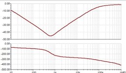
I should rather say wide band error amp instead of opamp because it must amplify the error without integrating it. The difference the error amp sees, is the same what the power amp sees, as the power chips are integrators in open loop, if the error amp also integrates the same input, it will become back an image of the output signal. To keep at high gain all the audio band, it needs 2 pole compensation for stability.
This type of amps have two independent stability character, the error feedback loop and the error correction frequency. If higher frequencies than the power chip are asked to get corrected, the chip amp will decrease its phase margin, this why the error amp receives the input via a low pass filter.
LM3886 ERROR CORRECTOR.JPG

I use the AD829 wide band opamp which can have its gain bandwith adjusted. This amp doesn't need servo as the error receives the DC component of the output without attenuation. The slight offset can be adjusted by the opamp offset adjust, not implemented on the model, so I adjusted by R7.
The LM3886 has OLG@20khz of 50db. With 26db CLG, only 24db NFB is left. With this error corrector 80-100db is possible.


The origin of Modulus86 from Mr Evil posted in 13 11 2004.
Thread 'Unnamed feedback method explored.' https://www.diyaudio.com/community/threads/unnamed-feedback-method-explored.45662/

Attachments

  • 10khz-1.JPG
    10khz-1.JPG
    25.8 KB · Views: 203
  • error output.JPG
    error output.JPG
    48.9 KB · Views: 205

Capacitor wire length for tests

Hello,
I do have some speakers I play with. The Crossovers are outside, same channel from the amp, speaker switch.
Main capacitors, 3.3uF (second order) are on the board, additional/bypass capacitors are connected via alligator/wires clips.
Does the length of wires affect the influence of the smaller capacitors to the main ones?
(Longer travel, slow speed of the electrones, late arrival at the main capacitor)
Practically, adding parallel capacitor upto 50% value of the main cap does not produce noticeable sound changes.
It seems to me, in cases the capacitors are soldered, the sound changes (as to be expected). Or it is result of imagination.
Thx

BGW 250D Power Supply Issues

I received this amp about a week ago and noticed that the bass was not as tight and coherent as I thought it should be.

Anyway, I spent hours today trying to install the new caps only to find out that the factory caps are tamper proof, and cannot be removed by any conventional means as the fasteners are cemented together.

I want to possibly attach a set of 18,000uf 75v caps to the originals for now if there are no issues in doing so.

My other issue is that the legs on the ceramic snubber cap for the rectifier failed so it is no longer attached. It is a .1uf Z5U @ 20% (M). I have no idea what the minimum voltage should be rated at for this amp.

Too much or too little gain?

There is a post from @chris mielke in the ba-3 thread that talks about too much gain from the ba-3. My question is, how does too much or too little gain affect the sound? Does it mean the sound coming out of the speakers has too much influence from the source and pre-amp and not enough from the amp? Or is it just as simple as the amp cannot offer the power it has and it doesn‘t have anything to do with the actual sound?

Cheap surface mount resistors from AliExpress, surprisingly low TC and tolerance

Since most kits I can get from reputable dealers in Germany are thick film, thin film 1% are few and expensive, and MELF or 0.1% flat SMD kits are not listed or frightfully expensive, I just ordered three kits of 1% 0603, 0804, 1206 with 1500 parts each from AliExpress. I was expecting thick film and poor tolerances. When I looked that the little strips, they had been hacked right through resistors, leaving 25 intact resistors in each strip. Some were not great, i.e. the metallization on one side would be three times the width of the one on the other side.

Well, I started with the 1206, tested four different nominal values 2-3 each depending how many fell from the strip when I peeled back the foil. The largest deviation from nominal I found was 0.45%. I then put the resistors on an electronic hot plate set to 82°C, exactly 60°C above RT.

The 300 k resistors had a negative TC between 17 and 38 ppm/K.

The 5k6 and 20k were all between + 12 and +17 ppb/K. The 680 R were at -50 ppm/K. This is thin film territory, even if not precision thin film. Going back to the listing, it said thick film. Can this really be thick film? Operating temperature, TC and rated power were all listed as "standard".Wonder what I got there.

Is there a good way to measure coefficient of voltage? Or maybe I just should measure a resistive divider (e.g. 20 k / 680 R) with a high voltage swing for distortion?

Thoughts on my proposed new Ian Canada build and help moving it forward

Parts List:

M.2 - 1TB (Type B key)
GeeekPi SSD Storage Expansion Board w/USB 3.1
TransportPi AES
FiFoPi Q7
ReceiverPi DDC
ShieldPi Pro
MonitorPi Pro
Raspberry Pi 4B
PurePi 3.3V/5V

The list above is also my proposed build order. Does it seem correct or should I change the stack? If change is needed, how?
I also would like to know how I can mount this into a case and whether or not I need additional parts like Ians' Linear power module.
My goal is to have it all in a nice case I can put on my desk instead of looking unfinished like an erector set.

Currently I am waiting on the receiverpi and the monitorpi and shieldpi.

Here is a picture of it as it is now. I have since installed the M.2 drive and heatsink.

Looking forward to comments and advice!

- Mario

PXL_20231228_051252800.jpg

Last 13 sets of Semisouth SJEP120R100 + 2SK3497 for J2, Vgs matched at 55°C

As promised earlier here :
https://www.diyaudio.com/community/threads/semisouth-goes-dodo-what-now.222098/post-7303805
We are making available our last reserves of SJEP120R100 matched pairs for use in J2/F8.
Please read the above link for details.

On offer are 8 sets of :
1 pair of SJEP120R100, Vgs matched to 40mV at 55°C
1 pair of 2SK3497, Vgs matched to 20mV at 55°C
Registered air mail from HK plus extra insurance (not available to certain countries)
For 1800HKD per set.

Conditions same as previous GBs for Semisouths and 2SK3497s.
https://www.diyaudio.com/community/...r100-curve-tracer-matched-pairs-quads.330916/
https://www.diyaudio.com/community/...-matched-2sk3497-2sj618-quads-at-55-c.397291/

This is even less than the price for a pair of unmatched Semisouths alone offered on ebay.
But we shall leave this open for a few weeks, because of the high values.
And then we also have no more Vgs-matched pairs to offer after this.

In addition, we have, left from the last GB, last 3 sets of curve-tracer-matched SJEP120R100 pairs.
They can be supplied with equally tightly-matched 2SK3497 pairs.
These on request only, as I want them to find good homes and get used in builds.
Please only ask (by PM) if seriously interested to build with them.


Patrick

PS was just told by XACOO that we only have 8 sets left, not 13 sets. My mistake.

My B1 Nutube Korg with touch panel

Hello everyone,

this is my Nutube Korg B1 preamp with STM32f469i-disco touch screen. And I have been enjoying music with him for more than 3 years. And thanks again Nelson

Attachments

  • tempImagecc1gDn.gif
    tempImagecc1gDn.gif
    1.6 MB · Views: 165
  • tempImagexmsbpV.gif
    tempImagexmsbpV.gif
    1.4 MB · Views: 162
  • tempImageRXZWYx.gif
    tempImageRXZWYx.gif
    1.2 MB · Views: 162
  • tempImageaa2Gin.gif
    tempImageaa2Gin.gif
    1.5 MB · Views: 168
  • tempImageCDnmJF.gif
    tempImageCDnmJF.gif
    1.5 MB · Views: 182
  • tempImaged8qNYT.gif
    tempImaged8qNYT.gif
    1.1 MB · Views: 174
  • tempImagemfsfgD.gif
    tempImagemfsfgD.gif
    1.3 MB · Views: 168
  • tempImagefjbYQK.gif
    tempImagefjbYQK.gif
    1.1 MB · Views: 150
  • Vstup_atten.pdf
    Vstup_atten.pdf
    109.1 KB · Views: 79
  • Zdroj.pdf
    Zdroj.pdf
    44.7 KB · Views: 110

2 Way driver advice with CHN-40 driver for top end

In the process of making Frugel-Horn Mk3 speakers and some bigger stand mounts to replace small near field computer speakers which have Mark Audio CHN-40 drive units.
Now that the CHN-40 are spare I thought of using them in a 2 way, using them for high frequency duty. This is new to me as I have never made a crossover, please correct me if wrong but the CHN-40 would need to be in its own sealed part of the box. What size woofer would be a good match, low bass is not a problem, sealed box for both okay.
How would I size the volume for the CHN-40 and the woofer to work out the crossover. Sorry for so many questions, big leaning curve compared to single drive unit box and very easy to get wrong.

Converting Harman-Kardon Citation Twelve from BJT to MOSFET output

Thank you to Nelson Pass for providing instruction on converting the HK Citation 12 to a mosfet output. I have one sitting on the shelf and this is a project I’ve been wanting to do for fun for awhile. I had a couple of questions and was hoping to get direction.

First, the instructions are older, I’m guessing not, but are there any layout pics that are a little clearer? The schematic is no problem at all though.
IMG_1189.jpeg


IMG_1187.jpeg

This design being older I was thinking I’ll have to substitute parts. The outputs used are IRF-130 which are TO3 packaged MOSFETs. I was thinking I would swap to a TO3p package and use the IRFP240, would that be a good swap for the outputs?

The transistors being used are MPSL01 and MPSL51. What would be a good replacement for these? I have a bunch of 2N5401c and 2N5551c and was thinking maybe those would be appropriate. MPSA92/MPSA42? I have thousands of the 2N5401/2N5551 though so would prefer to use those.

Dan
  • Like
Reactions: huggygood

Dodge Durango FR response

Since i bought durango, i was curious about parameters of its audio. Mainly fr response. First durango i got was with beats system. Sounded boomy. Horrible nasty resonating sound. Just like beats brand headphones.
I returned the car under warranty for other reason. New one i got has premium alpine 9 speaker system. However it sounds the same. Not better.
So i measured fr response with rew.
Next few post are results. Pretty self explanatory.

Gnuplot in VM on Mac... x86/64??

Ned som PC/Win help as I pectially never use these systems... I'm trying to install gnuplot on my windows machine running on an UTM VM hosted on a macOS M3 laptop.

When I download and try to install gnuplot

gp601-win64-mingw.exe from https://sourceforge.net/projects/gnuplot/files/gnuplot/6.0.1/

I get this message:

x64.jpg


This is the spec for my win machine:

win.jpg


Whats not right here?

That it says "system32"?

What did I do wrong?

//

NEUMANN V475-2A Summing mixer- asymmetrical output, limited headroom, Help needed.

Hi all, I built a 24x2 summing mixer with a passive odd/even input with resistors 5,1kΩ as Re, and a NEUMANN V475-2A mixbuss board before the stereo output. The situation is like this. When I connect the built to my audio interface, if I feed the mixer with -18dBFS 1kHz sine test tone to any of the inputs, I get unity level (-18dBFS) back to the DAW when a variable stereo pot (20kB) that I connected as Rg reads 6,2kΩ. I understand that this is correct and as expected, but, if I raise the level by 1 dB (either from the input or the output of the V475 [Rg])I can hear and see that the tone starts to distort. It seems that the headroom of the V475-2A maxes out at -18dBFS. I have also noticed that the pot raises the level of the output until it reaches 15kΩ, but it is not a clear sine after 7kΩ (1-2 dB) over unity gain, unless I compensate for that level raise, from the input. I connected the pins of the xlr out of the summing mixer to an oscilloscope and I saw that the level of the + and – pin has a ½ level difference. If I sweep the input test tone there is no difference from 20Hz up to about 100Hz but for the rest of the spectrum the – pin is about half the amplitude all the way up to 20kHz. When I feed a stereo signal to the mixer and back to the DAW the waveform is asymmetrical ( I took a screenshot from the DAW) if the levels are higher than -18dBFS. In this example levels are -0.5dBFS I/O. I changed all the electrolytics including the ones in the power rails, but nothing changed. I changed the NE5534AN twice with new op-amps, nothing changed. I measure the power supply, voltage and current and is up to specs. If anyone from the community with electronics skills and knowledge on this board - because I don’t have any-, could give me a hint as where I could possibly look for, his/her help would be much appreciated.

Regards,

Nikos Kefaloyannis

Attachments

  • Screenshot 2024-06-13 at 14.14.52.png
    Screenshot 2024-06-13 at 14.14.52.png
    179.6 KB · Views: 82

For Sale Used Black Gate FK and N series Capacitor

Black Gate FK and N series Capacitor

These are gently used and still lot of life available.

Details are in images, please refer.

I will sell all as a package at very reasonable price of $125 including shipping and PayPal charges.

Shipping to Worldwide at buyer's risk, but it will packed carefully.

Shipping to world will be through INDIA post Registered mail which will take 2-4 weeks.

Thanks for looking.

Attachments

  • IMG_4027.JPG
    IMG_4027.JPG
    380.3 KB · Views: 303
  • IMG_4028.JPG
    IMG_4028.JPG
    542.6 KB · Views: 318
  • IMG_4029.JPG
    IMG_4029.JPG
    597.9 KB · Views: 309
  • IMG_4030.JPG
    IMG_4030.JPG
    571.8 KB · Views: 298
  • IMG_4031.JPG
    IMG_4031.JPG
    672.6 KB · Views: 268
  • IMG_4032.JPG
    IMG_4032.JPG
    530 KB · Views: 254
  • IMG_4033.JPG
    IMG_4033.JPG
    500.6 KB · Views: 249
  • IMG_4034.JPG
    IMG_4034.JPG
    432.5 KB · Views: 303

How did Hammond Organ make the AO-41 work?

Back before any of us were born, before Countryman made their op-amp based phase shifter, someone at Hammond designed this and made it work well enough to build into product;

1717630023089.png


I understand they're pulling current back and forth through the SR 10X transformers windings as controlled by the vibrato oscillator. I understand that those transformers (must be?) mag amps, so when the DC current level is high, they restrict AC from passing through the secondary windings. These days we could use a Vactrol for such a function, but being 1947 or so, they only had "sticks and stones" to work with. (as a former boss once said about our PS design lab)

My question is understanding mag amps are good for things like power supplies, stage lighting, locomotive braking - stuff where you dont care "how it sounds" as the technique introduces a large amount of harmonic distortion, how did they make it work successfully as an audio level control element? I'm pretty sure Hammond would not tolerate the tone of their organ getting all smashed for a little vibrato, even if it beats tremolo.

It cant be that easy. Then why could I not take a cheap 70V line transformer, put some DC / Vibrato frequency AC through the 70V side and render me a "mag-amp" based variable AC attenuator on the speaker side winding? And have it sound just like a variable resistor would? Or, would I need a gapped SE OPT to get close to that ideal? Or - is there truly zero hope of rendering such a thing out of junk you happen to have lying around; you need the custom build transformers Hammond designed for the above circuit? And even then, it only works for miniscule AC currents in the secondary.

Rebuilding my BK Sonata series components, starting with the amplifier, EX-442 Sonata and I need new MOSFETs, go Exicon???

I have this three-piece set utilizing the EX-442, MC-101 and TS-108 tuner. I am wanting to go through and freshen them up a bit as I found they were having a problem. Playing them they sound fantastic, but one day I was driving them fairly hard, and I found some popping noises coming from a mid range in a pair of my JBL L7 towers. I happen to have a few pairs of these, so I swapped out the mid range and sure enough it was doing it again. Through some testing and swapping of cables I found the problem to be the amplifier. That’s when I read that, this was likely a mosfet getting noisy.

First off, what is the best method of determining which mosfet is the culprit?

So it used 2SK1058 and 2SJ162 mosfets. I was hoping to get an idea of how good these devices are. Would it be better for me to try to seek out originals and hope that I don’t have to replace too many to eliminate the noise? My other option is to buy all new mosfets from Exicon. It looks like the ECX10N20 and ECX10P20 would be the appropriate replacements for these. If I did go this route, then I would probably buy a couple sleeves of each, having 60 of each on hand for future projects. Then at a later time get the bigger ECW20N/P20, or would these be better in this situation now? I’m guessing the ECX would be just fine as it is rated to be a bit more robust than these originals.

How do these new devices compare to the originals of the amplifier? I know when it comes to BJTs there are certain devices out there that are considered superior sonically and are coveted. You wouldn’t replace these with any new modern device as it would be a downgrade. I’m just trying to see if this is a similar situation.

Thank you,
Dan

The Cyrus Tuner voltage is too high for the front lighting lamps

The Cyrus Tuner voltage is too high for the facade lighting lamps, because the primary of the transformer is 220V, now we have 240V. I changed the lamps because they were burnt out. I replaced them with the same 12V 60mA lamps. So I need to lower the voltage which is currently 23V to 12V. I took the same diagram as the 317 already installed for other 5V, 13V and 24V use. I need your opinion, is this addition good? or do you have another solution other than a drop resistance.

hfe_cyrus_tuner_service_en page 41.jpg


hfe_cyrus_tuner_service_en page 41 lm317 zoom3 with modif.jpg

HPS 6.1

Here's for your free non commercial use the last implementation of my phono preamp: HPS 6.1

What's new:

- A new servo in the head amp, allowing the use of an active load in the low noise stage; as a result, the PSRR is improved by an order of magnitude.
- A new power supply, much simpler, using the latest ultra low noise regulators from TI. TPSA7A4700 (positive) and TPSA7A33 (negative).

You will find attached the schematics and the Gerber files (including this time the much requested solder mask). The board size is 124.5 x 81.3mm so the construction is very compact. Any questions, feel free to ask. For the time being, only a few comments:

- It is dual mono, and requires separate raw power supplies (recommended +20V @250 mA -20V @50mA) for each channel (if you want to keep it dual mono all the way). Double the currents if you are using a single power supply for both channels.
- Supply voltages are +/-18V. This being said, you can replace the LME49610 high voltage buffer (now exctinct) with the lower voltage version LME49600
- For the low noise jfets, you can replace the now extinct BF862's with the still in production at OnSemi 2SK3557 or CPH3910 with a less than 5% penalty in noise. For the 2SK3557 choose the -6 rank (lower Idss).
- I have two more versions, one uses the OnSemi CPH5905 integrated cascode (same noise performance as the 2SK3557) and one using standard LM317/LM337 linear regulators (almost the same noise performance, board is slightly larger). The latter was a proof of concept to showcase the very good PSRR of the input stage, but I would still recommend the current version. I may eventually post these versions as well.

And a strong WARNING. This construction is not for the beginners. It is full SMD and while most of the parts are a convenient 1206 size, some are smaller 0402 and the TI ultra low noise regulators are in DFN package, difficult to solder. Skills in SMD soldering and the use of a hot air soldering tool is mandatory for success.

Finally, I have to add the usual disclaimer: I am not into group buys, selling boards, building BOMs for DigiKey or Mouser, etc... life is too short for such, so essentially you are on your own. Information herein is accurate to the best of my knowledge. This will be posted on my web site, as soon as I'll find time to do it (I am hopelessly in behind updating my web site).

Enjoy!

09/17/2019 Schematics corrected here: https://www.diyaudio.com/forums/analogue-source/333000-hps-6-1-a-4.html#post5917513

Attachments

Looking for: connector RTW 1069A

Hello,

I am looking for a connector assy for an RTW 1069A.
Please see attached photos of what I am looking for.
Should you have one that you don't use please PM me.

Thanks!
Vencel

Attachments

  • 441990949_1022950629252360_3408838145677273712_n.jpeg
    441990949_1022950629252360_3408838145677273712_n.jpeg
    318 KB · Views: 56
  • 445373043_830533678504000_8628966834180644992_n.jpeg
    445373043_830533678504000_8628966834180644992_n.jpeg
    272.1 KB · Views: 53
  • 445380669_3722359888011512_7680971463675067866_n.jpeg
    445380669_3722359888011512_7680971463675067866_n.jpeg
    223.8 KB · Views: 53
  • 445382868_1452076682082424_1596496978072712563_n.jpeg
    445382868_1452076682082424_1596496978072712563_n.jpeg
    251.7 KB · Views: 50

Intro thread

HI folks

Been a silent visitor to this forum for a long time... I am a electronics geek and recently successfully brought back my Sub Woofer from the dead. Had a blown zener and dry solder at diode. But i am not happy with the result i want to get more into it and explore more .. ofcourse using my sound system as the guinea pig. So here i am starting on a very frustrating (comes with the territory) but rewarding journey.

Welp, it's been ten years, may as well say hi

Joined April 17, 2014. Been quite happy to lurk all this time but finally found something comment-worthy so I guess it's also time to get my intro post out of the way.

I like old integrated amps, guitar amps and echo effects, pipe organs, and working on my cars. I hate snake-oil bullsh... wait, can I say that here?

I have two cats, two very elderly BMWs, and by the grace of god alone a wife who finds these aspects of my life charming. Ain't it grand, folks?
  • Like
Reactions: Jason

PAM8610: Same part number, different parts

I’m using the PAM8610 breakout boards in an application where I rely on the “ramp-up/ramp-down” volume when the MUTE pin is used with the FADE pin tied low. I‘ve used over 20 of these boards with great success. I went to purchase more of these boards, and I’ve found that there are new versions of the PAM8610 IC with a subset of features, fewer pins in a smaller package, and yet they are still marked PAM8610. The new devices have 32 pins, whereas the original has 40. I suspect that the new devices are in fact PAM8006A—which is similar to the PAM 8610, but without the volume control and the FADE feature that I need in my application. In the photo below, the left-hand board is the original, the middle board I purchased from Amazon, and the right hand board I purchased from eBay. The left board has the 6mm square 40 pin package while the other two have the newer 5mm square, 32 pin packages.

The new boards do not have the FADE feature—they just snap from full volume to zero and back when the mute pin is toggled.

Current versions of the data sheet for the PAM8610 are marked “Not recommended for new design, use PAM8006A”. I’d like to purchase some of the old boards before they are totally gone.

The PAM8610 seems to have quite a following on this forum. Have others encountered this issue? Is there a source of supply for the original board? How can I ensure that the vendor is selling the old board when the parts are labeled with the same part number?

1715965514721.jpeg

Large set of NOS 400 V 2% NSF polystyrene capacitors (RIAA network)

Selling this large lot of polystyrene caps, weighing a few kilograms. Revenue goes to the person I bought this from, it came with a lot of mustard caps that I was interested in. Seems to be quite unique in the sense that it has high voltage and high precision, and there's a large amount of values to chose from. I rather try to sell it on diyAudio, but if nobody is interested, I will place the lot on ebay at a starting price of 0.01$.

I have a B&K Precision 890C and tested a few large value caps, they were all within the range. I can do more measurements on request.

This is the full list of caps:

400V

89800​
pF
6​
x
84800​
pF
5​
x
80000​
pF
5​
x
75600​
pF
4​
x
71400​
pF
4​
x
67300​
pF
3​
x
63600​
pF
4​
x
60000​
pF
4​
x
56600​
pF
5​
x
53400​
pF
4​
x
50400​
pF
3​
x
47600​
pF
3​
x
44900​
pF
2​
x
42400​
pF
2​
x
40000​
pF
2​
x
37800​
pF
3​
x
35700​
pF
2​
x
33700​
pF
2​
x
31800​
pF
2​
x
30000​
pF
2​
x
28300​
pF
2​
x
26500​
pF
2​
x
25200​
pF
2​
x
23800​
pF
3​
x
22400​
pF
2​
x
21200​
pF
5​
x
20000​
pF
5​
x
18900​
pF
8​
x
17800​
pF
9​
x
16800​
pF
5​
x
15900​
pF
4​
x
15000​
pF
3​
x
14100​
pF
5​
x
13300​
pF
5​
x
12600​
pF
5​
x
11900​
pF
7​
x
11200​
pF
4​
x
10600​
pF
5​
x
10000​
pF
5​
x
9510​
pF
5​
x
8980​
pF
7​
x
8480​
pF
27​
x
8000​
pF
19​
x
7560​
pF
4​
x
7140​
pF
5​
x
6730​
pF
5​
x
6360​
pF
5​
x
6000​
pF
4​
x
5660​
pF
2​
x
5340​
pF
6​
x
5040​
pF
5​
x
4760​
pF
4​
x
4490​
pF
9​
x
4240​
pF
8​
x
4000​
pF
22​
x
3780​
pF
13​
x
3570​
pF
17​
x
3370​
pF
14​
x
3180​
pF
12​
x
3000​
pF
13​
x
2830​
pF
17​
x
2650​
pF
12​
x
2520​
pF
15​
x
2380​
pF
9​
x
2300​
pF
5​
x
2240​
pF
7​
x
2120​
pF
36​
x
2000​
pF
5​
x
1890​
pF
8​
x
1780​
pF
10​
x
1680​
pF
11​
x
1590​
pF
30​
x
1500​
pF
12​
x
1410​
pF
10​
x
1330​
pF
7​
x
1260​
pF
4​
x
1190​
pF
7​
x
1120​
pF
9​
x
1060​
pF
6​
x
1000​
pF
13​
x
951​
pF
4​
x
898​
pF
7​
x
848​
pF
3​
x
800​
pF
7​
x
756​
pF
3​
x
714​
pF
5​
x
673​
pF
3​
x
636​
pF
4​
x
566​
pF
6​
x
534​
pF
2​
x
504​
pF
7​
x
476​
pF
4​
x
449​
pF
3​
x
424​
pF
7​
x
400​
pF
8​
x
378​
pF
9​
x
357​
pF
11​
x
337​
pF
6​
x
318​
pF
8​
x
300​
pF
1​
x
283​
pF
11​
x
265​
pF
16​
x
252​
pF
7​
x
238​
pF
7​
x
224​
pF
6​
x
212​
pF
10​
x
189​
pF
4​
x
178​
pF
5​
x
168​
pF
3​
x
159​
pF
25​
x
150​
pF
2​
x
141​
pF
5​
x
133​
pF
2​
x
126​
pF
3​
x
119​
pF
1​
x
112​
pF
1​
x
106​
pF
20​
x
100​
pF
1​
x
95​
pF
2​
x
90​
pF
1​
x
85​
pF
15​
x
80​
pF
3​
x
71​
pF
5​
x
68​
pF
18​
x
63​
pF
4​
x
59​
pF
3​
x
27​
pF
43​
x

Also includes an amount of 2% 350V caps

44900​
pF
4​
x
42400​
pF
4​
x
40000​
pF
5​
x
37800​
pF
4​
x
35700​
pF
5​
x
33700​
pF
4​
x
31800​
pF
5​
x
30000​
pF
4​
x
28300​
pF
4​
x
26500​
pF
3​
x
25200​
pF
4​
x
23800​
pF
6​
x

And some 500V

10000​
pF
9​
x
8000​
pF
11​
x
6000​
pF
10​
x
5000​
pF
1​
x
3000​
pF
10​
x
2500​
pF
10​
x
2000​
pF
18​
x
Large quantity 1000-2000
Large quantity 50-1000

Attachments

  • 20240610_192641.jpg
    20240610_192641.jpg
    714.8 KB · Views: 100
  • 20240610_192807.jpg
    20240610_192807.jpg
    351.9 KB · Views: 66
  • 20240610_192815.jpg
    20240610_192815.jpg
    694.1 KB · Views: 71
  • 20240610_192958.jpg
    20240610_192958.jpg
    497.8 KB · Views: 61
  • 20240610_193053.jpg
    20240610_193053.jpg
    747.7 KB · Views: 65
  • 20240610_193841.jpg
    20240610_193841.jpg
    412.8 KB · Views: 66
  • 20240610_194019.jpg
    20240610_194019.jpg
    772.4 KB · Views: 78
  • 20240610_194207.jpg
    20240610_194207.jpg
    700.7 KB · Views: 60
  • 20240610_195030.jpg
    20240610_195030.jpg
    754.8 KB · Views: 77
  • 20240610_195537.jpg
    20240610_195537.jpg
    772.9 KB · Views: 49
  • 20240610_195931.jpg
    20240610_195931.jpg
    704.6 KB · Views: 69
  • 20240610_202150.jpg
    20240610_202150.jpg
    711.6 KB · Views: 52
  • 20240610_210407.jpg
    20240610_210407.jpg
    715.4 KB · Views: 54
  • 20240610_210412.jpg
    20240610_210412.jpg
    688.4 KB · Views: 55
  • 20240610_214318.jpg
    20240610_214318.jpg
    532.1 KB · Views: 68
  • 20240610_214328.jpg
    20240610_214328.jpg
    685.1 KB · Views: 65
  • 20240610_214332.jpg
    20240610_214332.jpg
    522.3 KB · Views: 52
  • 20240610_214335.jpg
    20240610_214335.jpg
    648.1 KB · Views: 53
  • 20240610_214338.jpg
    20240610_214338.jpg
    649.6 KB · Views: 62
  • 20240610_221401.jpg
    20240610_221401.jpg
    518.6 KB · Views: 68

enamelled wire properties

i want to pre-calculate the self capacitance of some transformers I need to design. To do that I need the thickness and dielectric constant (permitivity) of the enamel. When wire came from major western manufacturers, one could get that from the manufacturer. But I need to get data for wire of uncertain provinence (ie bought on eBay from Chinese sellers).
Is there an easy way I can measure thickness and dielectric constant of a sample of wire?
It is not sufficient to just measure the overall diameter with a micrometer, as the manufacturing tolerance on copper wire diameter is too large. I tried scrapping of the enamel so I could measure the copper diameter accurately but got inconsistent results - it is hard to tell whether I am scrapping off copper. I tried burning off the enamel with a gas flame, but that gave inconsistent results too.
Keit

5881 PP Restoration

I rescued a 5881 mono block from a relative and in the process of restoration. I assume it was build in the 1950s and remember listening to it in the 70s. This is a little over my head. My experience has been building known circuits with plenty of information online. I have replaced all of the mouse chewed wires, new sockets, checked and replaced passive components. With a little bit of research it looks to have a Van Scoyoc phase splitter? My first questions are the following:

Why two inputs? If I split a mono signal into both inputs it seems to cancel each other out. When I ground one input, works fine. A Mac C104 clone was used as a front end and from what I could tell from the remnants it didn’t have two outputs.

Don’t need to worry about oscillation?

Based on other articles I read should I have a balanced bias circuit on the 5881’s?

I recently acquired another output transformer so I want to make sure this is sound before moving forward with that.

Thanks,
Steve

Attachments

  • IMG_2483.jpeg
    IMG_2483.jpeg
    469.2 KB · Views: 289

Question about choke & resistor values in bipolar power supplies

Hi there,

Pretty simple beginner stuff here, but I don't really do much with transistor amps so I have never built a bipolar supply...

If I were to build something like this, delivering B+ and B+/2:

1000004322.png


(...from the tubecad article here: https://www.tubecad.com/2012/05/blog0230.htm )

...in this illustration there are two resistors, I plan to use chokes but nonetheless - do the values of the chokes or resistors need to be identical?

If so, finding choke pairs is difficult. I would be motivated to build a stereo power supply if I'm going to purchase chokes. If the total demand on the power supply is about 300mA from both legs together, do both chokes need to be rated for that?

If the chokes do not need to be identical, the question of current remains. Can I have the top leg with a 200mA, as the output tubes take the larger voltage and the lion's share of the current, and a 100mA on the lower leg? The caps blocking DC make me think that this is the case... but as I looked up more examples of this kind of circuit, I kept finding that they had identical R values so... just gotta confirm...

Selecting shielded input wire for passive preamp

Greeting,

I recently had my +10db gain tube pre develop issues with it's muting relay. Which caused a channel imbalance so I'm in the process of swapping the relay. This caused me to insert my 0db gain passive temporarily. Which has caused quite a welcome ruckus on the analog end. As before I was experiencing pretty substantial subsonics that would end up effecting the tonearm producing compounding issues at higher volumes.

To make a long story short awhile back I had run all of the math on the adjustments on my hybrid phono pre. And found that with one setting, with this cartridge, that I could boost the phono output by around 6%. So the usual occured with the other sources, and especially with the CD player, the passive preamp lacks the last couple of volume clicks. Which has always been the case. But with the phono input it is just a giant step forward here. As the gain is sufficient and the noise and subsonics have for the most part vanished.

So I've determined that I'm going to add a set of passive outputs to my +10db tube preamp. And perhaps even a toggle that will mechanically select between active or passive.

This means that I'll have to source a appropriate shielded twisted input wire to add between the volume control and the switch and output jacks. And that has me pondering what type and guage to use. I'd like to perhaps introduce a tad more spice so I'm thinking silver or silver plate in a smaller guage. I've noticed the designers in this case have switched to copper from the past silver plate. At least in the active designs and they dropped the passive model from the lineup. So any thoughts on the best wire to use to introduce a little sparkle along with a tad more meat on the bones?

Many thanks,
DD

HELP: need advice on how to widen driver mounting hole rebate

I have some old speaker cabinets that have rebated driver mounting holes - these are old subwoofer cabinets. I have several drivers that would work in these cabs but the driver frame OD is a few mm too large to sit in the recess. I would very like to use these drivers and cabs together, so I am looking for ideas to either:
(a) use something like a Dremel tool to grind/sand the rebate edge, going round and round while sanding, until wide enough. I am concerned that I might not be able to sand the very bottom of the rebate sidewall, or I might damage the veneer on the face by doing this.
or
(b) forget about the rebate - create a ring of wood to fill it in and mount the driver with its frame proud of the cabinet face. This would waste a lot of material, but would not require sanding.

Any other ideas? Advice?

New project: 2way U18RNX D2604

For a long time I wanted to try one of Seas midwoofers, U18 seemed to be well balanced for midwoofer duty in 2way, though there was not many good measurements available from which I could judge the driver. D2604 limited edition discovery tweeters got to my hands, and I have to ay I like them a lot, at least the measured performance for now.
U18: I am very please with its FR linearity. It is very easy to work with a to make a crossover.
Initial crossover is attached, and in coming weeks I will optimize it and arrange the first listening tests.

More details: https://pkaudio.webnode.cz/u18d2604/

Attachments

  • 20240224_144209.jpg
    20240224_144209.jpg
    130.3 KB · Views: 299
  • 20240224_144234.jpg
    20240224_144234.jpg
    204 KB · Views: 285
  • D2604 H0-90 gated.png
    D2604 H0-90 gated.png
    75.7 KB · Views: 215
  • D2604 dist.png
    D2604 dist.png
    40.2 KB · Views: 189
  • U18 H0-90 gated.png
    U18 H0-90 gated.png
    95.5 KB · Views: 186
  • U18 dist.png
    U18 dist.png
    66 KB · Views: 198
  • v2 Directivity (hor).png
    v2 Directivity (hor).png
    16.1 KB · Views: 189
  • v2 GD+Phase.png
    v2 GD+Phase.png
    8.7 KB · Views: 192
  • v2 Impedance.png
    v2 Impedance.png
    8.8 KB · Views: 189
  • v2 Power+DI.png
    v2 Power+DI.png
    11.7 KB · Views: 202
  • v2 SPL.png
    v2 SPL.png
    8 KB · Views: 261

Good to meet you all

I'm fairly new to DIY, but I've been visiting and reading threads here for years now. Sorry I took so long to say hello, and it's good to finally meet you all.

P.S. I know there is a community of people who like to mod the speakers of a certain Andrew Jones Pioneer line. If local to Los Angeles, CA and interested, I have the entire line, minus the floor standers. They can be yours for the price of one pizza per speaker.

It is the
Pioneer SP-BS22-LR line, including the upgraded models with the vertical firing woofers.

Best Online Reads on Room Acoustics for Dummies?

Troy Crowe, whose building my speakers, recommended this book https://shop.shakeandco.com/book/9781138921368

But none of my local public libraries have it and I don't know how math intensive it is to even think about buying it,

Can anyone recommend another book and/or ONLINE sources, BUT essentially for dummies-or at least math challenged dummies?
  • Like
Reactions: otto88

A Denon DCD-2560 with a broken load tray gear

Hello to all - new to the forum, and I have a very difficult problem on my hands!

After installing new load tray belts in a Denon DCD-2560 single CD player from the early 1990's and after testing it with a few open/close cycles. the drawer failed to open. Inspection showed that the gear that moves the entire rack back and forth had broken - not just a crack, but a section of the gear broke away. Luckily all teeth are still intact, and it fits back together correctly.

The tricky part with this gear is that is uncommon - it has 7 teeth and is rather small, and is made out of nylon/delrin plastic. I tried to super glue the gear back together and let it cure overnight. This worked for about 100 open/close cycles, but eventually the gear didn't hold together. It's very difficult to glue this type of plastic, as much searching/reading has shown.

I'm looking to see if anybody has thoughts/ideas on how to get a replacement gear for this unit - many hours of searching have turned up 0 results. As well I'll consider having a gear 3D printed, but most of the online tools available to create a custom gear have a minimum requirement of 8 teeth on the gear. I know it may be possible to send the gear in, but I do want to keep costs under control in this situation.

As well if anyone has thoughts or experience on actually repairing nylon gears of this sort it would be greatly appreciated for any ideas! Thanks in advance!

Outside diameter of the gear is 9.75mm - hard to measure as no even number of teeth, but that's after many tries with the caliper.

gear-pic-1.jpg
gear-pic-2.jpg

wine toast

I want to make an imaginary and virtual toast together with all those people like me who don't want to give up in the face of the many problems that one encounters when one dedicates oneself to study and design in the audio field. when you start you are amazed because you discover an unexplored world then as you delve deeper into the topic many problems arise and you have to work hard to understand how to solve them. These difficulties are precisely the beauty of life because they encourage the brain to come up with a solution.
so cheers

WAW! MEH... 8"+2"

MEH speakers look pretty neat! Many of them seem like more output (+ expense) than I think is necessary for my space, so I'm considering a 2 way with a 2" and an 8". I have a sub to take care of the really deep stuff. I do sort of enjoy the conceptual "Wow! / Meh" juxtoposition.

I've kinda wanted to do a 2-way with a 2" FR as a low tweet for a while, but they're so low efficiency. I started thinking about wave guides for the tweeter, but then thought maybe it should be a MEH. The idea being to increase sensitivity on the 2" down to 500 Hz or so, and cross to the 8" between 500 and 1k, and hopefully keep the horn size domestically compatible. I have active / DSP available, but would like to be able to make a passive XO for it.

These are some buyout drivers I got a while back. These drivers are NLA
2" - Tymphany TC6FC02-04
https://www.parts-express.com/Peerl...ll-Range-Line-Array-Drive-264-1350?quantity=1

8" - DynaLab V22-DR-0003
https://www.parts-express.com/DynaLab-V22-DR-0003-8-Poly-Woofer-4-Ohm-299-4004?quantity=1

So I started to monkey with HornResp. I don't really know much about HornResp, so we'll see if the brain trust thinks I've done it right...

HornResp-2in.jpg


HornResp-8in.jpg

I started out trying to enter T/S directly, but that seems a little wonky and the T/S wizard seems better.

It looks like the MEH wizard simulates response like this... (2")
HornResp-2in-pwr.jpg

(and 8")
HornResp-8in-pwr.jpg


So, questions.
  • Have I done a reasonable job setting this up? I might wish for more HF extension from the 8", but I think it has to be some 11 cm down the horn given it's diam. I think these dimensions makes 27 deg center-to-wall, or 54 deg wall-to-wall for the horn, and 40 / 80 deg for the end flare to smooth the horn exit (square horn shape). Am I missing any best practices for choosing horn dims?
  • I see the power predictions for output pictured above. I didn't see any directionality prediction, is that in HornResp? Horns are all about the directivity so I was expecting something like that. On the other hand, I only specified sectional Sq Cm not horizontal and vertical dims so maybe HornResp couldn't hazard a guess. I had to make a spreadsheet to estimate horn the angles.
  • That woofer null I presume comes from the wave entering the horn part of the way down, and some of it going back up the horn and then coming back down and interfering. That makes sense to me. But also the woofer front chamber and horn entrance is going to be a bandpass, right? Does HornResp have any facility to predict that, or help choose the entrance holes for the 8"? I was considering going to a different program to simulate a bandpass to investigate entrance sizes / velocity.
  • HF response on the 2" falls off. 2" spec is 85 dB @ 2.8 V and basically flat to HF on-axis. Other simulators frequently show a lot of HF roll-off that doesn't appear on-axis. I'm sort of assuming that is what's going on here (total output vs on-axis?). Does anyone have experience with how real that might be?

Hmmm... anything else? I'll come back as I think of more questions / make progress...

Thx

DML speaker on canvas

Hello everyone,
my name is Shari. I am interested in establishing a small business in Israel that deals with commercial production of DML speakers. I am familiar with the extensive thread here about this technology, but I am lost there.
I want to initially manufacture commercial DML speakers on canvas, with the option for customers to have personalized printing. I remember some friends here who have shared their projects on canvas, and I would be happy to consult with them, but I still don't have the option for private messages.
I would appreciate it if you could advise me here, is my idea realistic from a commercial point of view, is it really possible to produce a speaker with this technology that covers a wide frequency range in high quality? If so, would a printable canvas be a good material as a panel? I would appreciate any help
Thanks in advance

Power Center

I fear that I may be in the minority here, but I am a fan of using products to improve my AC, in particular the Niagara series from Audioquest. I have played with quite a lot of these devices and found some degraded the sound of amplifiers, typically MOV type units.

Nordost is a company that shuns doing anything to the power other than having really good outlets and ground.

Which ever camp you fall in I was hoping that perhaps I could pique the interest of some SMart person/people and suggest that perhaps designing a DIY power center.
  • Like
Reactions: birdbox

Hoffman Strikes Again: Passive Radiator VS Adding Another Speaker?

I'm working on a set of bookshelf speakers (2 way) and keep running up against hoffman's iron law. I also read recently about purifi's SPK16 reference design, and they were able to get down to about 32hz, but that also had a lot of design choices that were based on the fact they have a facility to design all of these things in and a budget much larger than mine. Additionally, I'm going to use a hypex fusion amp, which means I will have an active implementation as opposed to a passive one which also opens me to much greater tuning options including things like a linkwitz transform.

With all of that said, purely from a performance perspective, would it be more advantageous to use passive radiators, or just add subwoofers on the sides and make the design a 3 way?

New TPA3255 dual mono in PBTL

As a many years happy user of TPA3255, I thought it might be a good time for an upgrade. So here it is:

1712588080209.png
1712588357403.png
1712588940343.png

1712587913810.png


It's a dual mono, PBTL, single power supply design with PFFB. 12V is generated internally with two LM5017. It uses standard heatsinks available from Mouser:

https://www.mouser.be/ProductDetail/984-ATS-TI1OP519C1R3

but they do need to be shortened at one side to fit them both on PCB.

Board is 4-layer 10x10cm standard thickness. Coils are CoilCraft SER2918 mounted vertically.

High efficiency LCR speakers with good stereo perfomance

Hello DIY forum,

I have plans to build high efficiency LCR speakers and I'm looking at SB Audience and Faitalpro units.

Bass doesn't need to dig really deep as I already have a dual LLT B&C 21SW152 subwoofer tuned @11Hz and a sealed corner sub with 4x Visaton TIW400 with QTC = 0.6

Left, center and right channel will all include:
Woofer: 2x SB Audience NERO-12MWN400D sealed with QTC = 0.6
Mid: 2x SB Audience ROSSO-6MW150D sealed with QTC= 0.5
Treble: Faitalpro HF10AK on RCF H100

Crossover frequencies will be approximately 250Hz and 1500Hz.

I could consider to replace the SB Audience Nero-12MWN-400D with a ROSSO-15MW500 for a slightly better response under 100Hz.

Amplification and filtration will be done with the Hypex FA253 (Or FA503 if that one handles lower impedance better). I'll use a 2nd order passive crossover on the HF10AK for additional protection. Measurement will be done with REW.

All units will be built into a TV wall with sturdy bracing to avoid resonances. The 12"/15" woofers will be built into the lower cabinets that get extensive bracing + double panel thickness. The mid woofers will also get sturdy enclosures with non parallel walls. The center speaker will be built into the lower cabinet under the TV and the L-R speakers might be built into separate cabinets that stand on each side of the TV. If I succeed this will be an extremely powerful home cinema system with very clean and non-technical look.

Who has experience with the above mentioned SB Audience woofers or alternatives? Who sees a fatal flaw reading all the above? I'll certainly post images when the build starts and I'm open for all criticism.

Turntable pitch slider: increases speed up or down?

So I have an older Omnitronics 2220 turntable. It’s a typical direct drive ‘DJ’ turntable.
However at some point since I have owned it, the pitch slider has ‘broken’. The TT still plays at the correct speed at 0, but if I move the slider up or down…. The speed increases (instead of increasing one way and slowing down the other).
I’ve had a look inside and can’t see anything obviously wrong.
There is some information on the turntable here, but not sure it helps me much.
Anyone able to suggest anything?! Thanks!

ProtoDAC KIT for sale (TDA1387 x8 and TDA1543 x2)

Hi, there. I'm selling TDA1387 and TDA1543 DAC HAT KIT. Soldering and assembly are required. The KIT contains both thru hole and three SMD1206 resistors. This already contains a TDA1387 x8 module. TDA1543 x2 module is sold separately.

Introduction:
  • This is a DIY I2S DAC HAT for Raspberry Pi. Without the need for USB / COAXIAL / TOSLINK signal conversion, this DAC is driven by the I2S signal pins from Raspberry Pi directly, simple yet effective.
  • TDA1387 is a 16-bit multibit DAC. Although this DAC was introduced in the 90’s but the sound quality can beat most of the modern DAC with proper design.
  • The components of this DAC HAT are carefully selected and of high quality. With proper power supply, this DAC HAT sounds warm, transparent, musical, rich, detailed, relaxed, and analogue. The bass response is surprisingly deep and punchy.
  • This DAC HAT can work with Raspberry Pi alone and is natively compatible with STEALTH V3. LPS is recommended when used with Raspberry Pi alone.
  • Select HifiBerry as the output device under the device setting.

Specification:
-Accepts 16/24/32 bits*, 44.1/48 kHz
-Output Level: 2Vpp
*Only the most significant 16bits are processed, other bits are truncated.

Disclaimer:
-TDA1387 is an very old IC and not in fabrication anymore. The TDA1387 IC on the module is either from old stock or disassembled. Although the module is sample checked, the quality cannot be guaranteed. Refund of this IC module is not accepted if it is found faulty upon arrival. Please consider buying the basic kit without TDA1387 if you do not accept this clause.

Price Options:
-Complete kit (TDA1387 included): HKD700
-Basic kit (TDA1387 excluded): HKD650
-Finished good (TDA1387 included): HKD830
-Shipping fee incurred depending destinations

YouTube demo:
Login to view embedded media
  • Like
Reactions: StevenCrook

Need some info on DIY Paradise Eva 1

I have been given ann Eva 1 LDR remote control preamp, single RCA inputs and outputs. But it came without a wall wart power supply.
Anyone know what voltage and current rating the PS should be?
Also, which is the input and output pair?
Guessing inputs on the outer side, outputs towards the middle of the back of the enclosure.
Hopefully the balance is okay. LDRs tend to drift with time, it has been my experience.
Thx in advance for any assistance.
Cheers
Luigi

Test circuit for 2SC1584

Hi guys.
I need to test some 2SC1584 transistors. They come from an older power amp, used in the power supply (+52v, - 52v and ground). There was a pop noise in this amp exactly where these transistors were placed and the amp stopped working. They somehow still check OK when testing with a multimeter.
My question is: I have another 24v power supply with a 2N3055 and it works. Since both transistors have the same pinout and similar datasheets, I was wondering if I could just switch these Transistors in order to see if they still work.

YST SW800

I asked yamaha support to replace the pcb power supply and they tells me
they stopped the manifacture
So and idea to find somthing else for replacing ?
I have the pcb and i see blows up the transistor burned and some diodes
Have some one else the same problem or someone knows somthing simmiliar like sw800 pcb psu to replace it?

Thanx alot Bill

Muses72320 remote controlled preamp with RCA to XLR converter

Hello guys. Bouth these modules and assembled in a case from audiophonics. I will redo the internal wiring, I dont like it.
I hooked it up to a source playing sin wave signal at 1kHy. I get 1.12V out of the source (SFF pc, Im in a hotel on a business trip). The preamp has 5 gain stages.
The toroids are 15-0-15 each. Opamp in preamp is NE5532P and in converter JRC4580DD.

When I set the gain to LvL0, I measure 2.54V on the preamp out, and about 3.8V from the converter when volume set to 0dB.
At gain LvL1 its 4V and 5.6V when set to 0dB
At gain Lvl 2 higher and then at LvL3 even more.
At Lvl5 I have almost 8,7V on the converter out to XLR. However, at LvL4 its 9.56V

Is the Muses module broken? Why such high voltage? I want to use it with a Hypex UcD180 power amp that will be build once I get home.

I have no experience or knowledge building preamps :d thats why I chose the modules. I thought just put it together and all will be fine.

Danny

Attachments

  • 1.jpg
    1.jpg
    366.1 KB · Views: 253
  • 4.jpg
    4.jpg
    537.4 KB · Views: 257
  • 20240124_192605.jpg
    20240124_192605.jpg
    420 KB · Views: 304

help with change a old tube radio into headphone amp with LL2765

Dear all,

I have an old tube radio (schema: https://gejoweb.wordpress.com/x-philips-b5x43a-schema/), with singe end EL84 output.

Now I would like to change the original output transformer into Lundahl LL2765, and used it in the line-in mode as a headphone amplifer (https://www.lundahltransformers.com/wp-content/uploads/datasheets/2765.pdf), given the output impedence for EL84 is around 5k.

My questions are:
1. Is it worthy to do so, given the old architecture of the original schema? Or it is a good idea to DIY a new one with the pair of LL2764?
I am also interested to know the possibility of reusing LL2765 for 300B.
2. What is the output impedence for 300B? I checked online, and got answers from 3k to 5k. What is the best performing impedence range for 300B?
3. Would LL2764 be a good fit for 300B?

Thank you.

Hello from Detroit, MI

Yes, as in Detroit, Detroit! Not the suburbs.

Before our move to Michigan, I was located in Lowell, Massahusetts. I spent a lot of time collecting and restoring vintage hi-fi and building a system that I was pretty content with. After our move, my wife and I were pretty tied up with working on our house. It was built in 1933 and contains a lot of original features–something that we really wanted as we both love architecture and the overall build quality of old homes. Now that a lot of our restorations are complete, I've been bitten by the hi-fi bug again.

This time though, I'm much more interested in DIY builds, specifically SETs.

Also interested in hockey, baseball, knitting, sewing, the Arts & Crafts movement, cats, etc.
  • Like
Reactions: Drbulj

Limiter / Clipper 2mV

I have an application which requires that an audio signal be limited to 2mVpp. After 2mV level, I want the signal to clip. Under 2mV, no clip. I have an opamp in the circuit, and can use this opamp as part of the clipping circuit. When the signal is below 2mV, the clipper circuit must not interact in any way with the signal. I'm looking at a diode clipper, etc.. Does anyone have an opinion on the "best way" to do this?
Projects by fanatics, for fanatics
Get answers and advice for everyone wanting to learn the art of audio.
Join the Community
507,909
Members
7,893,287
Messages

Filter

Forum Statistics

Threads
406,471
Messages
7,893,287
Members
507,909
Latest member
BenM74