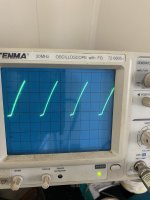
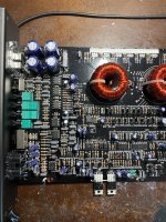
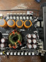
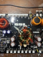
Do both of the output terminals of the 3525 look like that?
Are you sure that noting is wrong with the scope, probe or the settings?
What's the DCV on the output terminals of the 3525?
If your multimeter reads duty cycle and frequency, post what it reads on the output terminals of the 3525.
Are you sure that noting is wrong with the scope, probe or the settings?
What's the DCV on the output terminals of the 3525?
If your multimeter reads duty cycle and frequency, post what it reads on the output terminals of the 3525.
5.5. And now the drive looks fine. I’m going to refresh the solder and put the fets back in. Thanks anything I need to check first?
I was asking about your multimeter.
Any solder bridges on the output transistor pads?
DCV on all terminals of U1 after the amp has been powered up for about 10 seconds?
Pin 1:
Pin 2:
Pin 3:
Pin 4:
Pin 5:
Pin 6:
Pin 7:
Pin 8:
Any solder bridges on the output transistor pads?
DCV on all terminals of U1 after the amp has been powered up for about 10 seconds?
Pin 1:
Pin 2:
Pin 3:
Pin 4:
Pin 5:
Pin 6:
Pin 7:
Pin 8:
My multimeter doesn’t either. No solder bridges.
Pin 1. .08
Pin2. 2.87
Pin3. .52
Pin4. 0
Pin5. .16
Pin6. 2.87
Pin7. .13
Pin8 5.03
Pin 1. .08
Pin2. 2.87
Pin3. .52
Pin4. 0
Pin5. .16
Pin6. 2.87
Pin7. .13
Pin8 5.03
For the four 4-pin optocouplers to the left of U1, do any read more than a fraction of a volt of DC from pin 1-2?
Do any read near 0 ohms (power off) from pin 3-4?
Do any read near 0 ohms (power off) from pin 3-4?
If the positive terminal of EC14 is connectd to pin 5 of U1, pull the cap. Does pin 5 go to above 3v?
If not, desolder 1 terminal of R9 and check it. Is it within tolerance?
If not, desolder 1 terminal of R9 and check it. Is it within tolerance?
- Home
- General Interest
- Car Audio
- EV5000D


