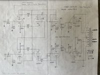
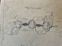
I rescued a 5881 mono block from a relative and in the process of restoration. I assume it was build in the 1950s and remember listening to it in the 70s. This is a little over my head. My experience has been building known circuits with plenty of information online. I have replaced all of the mouse chewed wires, new sockets, checked and replaced passive components. With a little bit of research it looks to have a Van Scoyoc phase splitter? My first questions are the following:
Why two inputs? If I split a mono signal into both inputs it seems to cancel each other out. When I ground one input, works fine. A Mac C104 clone was used as a front end and from what I could tell from the remnants it didn’t have two outputs.
Don’t need to worry about oscillation?
Based on other articles I read should I have a balanced bias circuit on the 5881’s?
I recently acquired another output transformer so I want to make sure this is sound before moving forward with that.
Thanks,
Steve
Attachments
I rescued a 5881 mono block from a relative and in the process of restoration. I assume it was build in the 1950s and remember listening to it in the 70s. This is a little over my head. My experience has been building known circuits with plenty of information online. I have replaced all of the mouse chewed wires, new sockets, checked and replaced passive components. With a little bit of research it looks to have a Van Scoyoc phase splitter? My first questions are the following:
Why two inputs? If I split a mono signal into both inputs it seems to cancel each other out. When I ground one input, works fine. A Mac C104 clone was used as a front end and from what I could tell from the remnants it didn’t have two outputs.
Don’t need to worry about oscillation?
Based on other articles I read should I have a balanced bias circuit on the 5881’s?
I recently acquired another output transformer so I want to make sure this is sound before moving forward with that.
Thanks,
Steve
Would love to see pics. What output transformer does it use? And is there negative feedback?
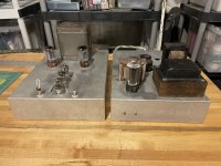
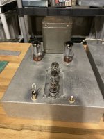
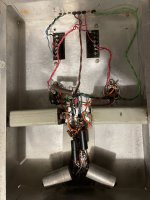
It came with the Peerless, which took me awhile, and $, to acquire another one. There is no negative feedback. Will snap some pix. Kinda jumbled in there 😀
Very cool, would love to see it. You're going to build a mate, I assume? If there's no global feedback then there's little chance of instability. Bandwidth will be reduced, but the S-265-Q is a great transformer so I hardly think you'd notice the rolloff while listening.
The schematic says Peerless S-265Q or equivalent. Also shows UTC S-16 (don't know this one). Right up your alley Grover.
John
Indeed! ;-) The Peerless is probably the better transformer. The UTC is a very old model, but it has 10K, 6K and 3K primaries. Great for a variety of PP triodes!
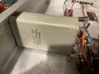
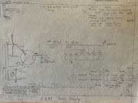
Here’s a couple of pics. Also included some of my notes. I tried to restore everything to the way I found it in the amp. It’s a real DIY project! The power supply is a little cobbled at the moment to get it to work. The Stancor C1003 choke did not make it. Yes, plan to create the mate, just want to make sure I have the circuit right before heading down that road. Those coupling caps are massive. Do you think I could go with a film auricap for the final build? Otherwise may have to take a chance on some Russian PIO’s.
Attachments
That's really something. I'm sure you can find smaller coupling caps. ;-) For the mate I'd go for the 378X over the 278X. I had a two 274BX that hummed and had to be replaced in a pair of monoblocks I built for a friend. Nothing we did would get rid of it, it was an issue with the windings.
Second for not using the 278. I just did in a PP KT-88 and the buzz is far worse than it should be, loaded or not. Nice amp Pamersa. The Russian pio .22 630v caps are not that large, and they perform very well in my opinion. But you can go with any non polarized cap that's rated for the voltage. 5u4 comes up pretty quickly so I'd go rated at B+ or >, but again the Russian pio .22 630v are not that large. At least compared to those, or Auricaps.
Loren
Loren
Thanks for the review, tips, suggestions. You are helping to break my logjam and start getting this done. I have two items on my list before I start ordering parts. I am thinking of moving to a smaller chassis since I don’t plan to use this oil can capacitors. From 14x10x3 to 12x8x3. Are there any issues moving the preamp closer to the amp tubes? Original has the last pre tube 3” and new layout would be ~2”. The other research item is the balanced cathode bias on the amp tubes. I found this topic, https://www.diyaudio.com/community/threads/push-pull-bias-balancing.357174/ .
So will start there. If you have any other suggestions, thanks in advance.
Thanks again,
Steve
So will start there. If you have any other suggestions, thanks in advance.
Thanks again,
Steve
No, there would be no problem using a smaller chassis, IMO. The pre/input stages won't pick up any hum from the power tubes. For output tube balance, I'd suggest the old Williamson method, shown below. It's of a suitable vintage. ;-) This actually feeds small percentage of the self-bias voltage to the grids of the output tubes, which acts like a bit of "fixed bias" to really nail the tubes in place. Instead of the test jacks, you substitute 10 ohm, 1/2 watt resistors, then add test points at pin 8 of each output tube. You then measure DC millivolts across the test points and use the pot to get as close to "0" as possible. This ensures a near-perfect match between the tubes, and also helps avoid one tube hogging the current and possibly running away. The total cathode resistance then becomes about 330 ohms. You could drop the main 250 ohm cathode resistor to 220 and keep the 300 ohm bias resistance in the original.

Trying to put my parts order together and getting hung up on the huge coupling caps between the last preamp, cathode follower, stage and the 5881. I am confused on why the Heathkit w-3 amplifier can use .25uf and mine has this massive 4uf oil can. I did some reading on coupling cap calculations. If I use .1Mohms (100k) for the grid (pin 5) from the 5881 data sheet plus the 1k in series , corner f as 5hz, plug that into the calculator it says 3.x uf . That would follow with the existing 4uf cap. Why the difference? Does the change in bias circuit come into play? If so, it would seem I should follow that .25uf value since I am going to implement that as well. That opens up the door for plenty of budget friendly caps. Choices for 4uf are looking slim. Thanks for any explanations or help resolving this.
- Home
- Amplifiers
- Tubes / Valves
- 5881 PP Restoration